EP0807574A1 - Methode und Vorrichtung zur Verstärkungsanpassung eines Kurvenflugkoordinators in Abhängigkeit von der Landeklappenposition - Google Patents
Methode und Vorrichtung zur Verstärkungsanpassung eines Kurvenflugkoordinators in Abhängigkeit von der Landeklappenposition Download PDFInfo
- Publication number
- EP0807574A1 EP0807574A1 EP97201290A EP97201290A EP0807574A1 EP 0807574 A1 EP0807574 A1 EP 0807574A1 EP 97201290 A EP97201290 A EP 97201290A EP 97201290 A EP97201290 A EP 97201290A EP 0807574 A1 EP0807574 A1 EP 0807574A1
- Authority
- EP
- European Patent Office
- Prior art keywords
- turn
- aircraft
- turn coordination
- coordination gain
- flap position
- Prior art date
- Legal status (The legal status is an assumption and is not a legal conclusion. Google has not performed a legal analysis and makes no representation as to the accuracy of the status listed.)
- Granted
Links
Images


Classifications
-
- G—PHYSICS
- G05—CONTROLLING; REGULATING
- G05D—SYSTEMS FOR CONTROLLING OR REGULATING NON-ELECTRIC VARIABLES
- G05D1/00—Control of position, course, altitude or attitude of land, water, air or space vehicles, e.g. using automatic pilots
- G05D1/08—Control of attitude, i.e. control of roll, pitch, or yaw
- G05D1/0808—Control of attitude, i.e. control of roll, pitch, or yaw specially adapted for aircraft
- G05D1/0816—Control of attitude, i.e. control of roll, pitch, or yaw specially adapted for aircraft to ensure stability
- G05D1/085—Control of attitude, i.e. control of roll, pitch, or yaw specially adapted for aircraft to ensure stability to ensure coordination between different movements
Definitions
- the present invention pertains to aircraft turn control systems, and more particularly, to a novel system that varies the turn coordination gain of the aircraft yaw damper as a function of aircraft flap position.
- a turn is coordinated through the operation of multiple control elements.
- a pilot will use the cockpit controls on a fixed-wing aircraft to manipulate the ailerons, rudder and elevator of the aircraft to execute the turn.
- the yaw damper includes various sensors on the aircraft and yaw damper servos that operate the rudder in response to signals from the yaw damper.
- Yaw dampers must determine the amount of rudder deflection for a given amount of bank angle as commanded by the pilot of the aircraft.
- U.S. Patent No. 5,452,865 to Tran and U.S. Patent No. 5,072,893 to Chakravarty et al. contain detailed discussions of prior art turn coordination systems.
- the gain schedule operates to provide turn coordination for the rudder during a turn maneuver.
- Known turn coordination gain schedules are based upon the parameter Q c , also known as impact pressure.
- the gain schedule for a Boeing 747-400 is shown in FIGURE 1. As seen, the turn coordination gain is constant until a critical air pressure, at which point the turn coordination gain decreases in a linear fashion. It has been found that the gain schedule shown in FIGURE 1 does not optimally provide for turn coordination, sometimes resulting in a divergent or convergent turn characteristic.
- the present invention provides an improved method and apparatus for determining the amount of turn coordination gain in an aircraft yaw damper system during a turn maneuver.
- the yaw damper includes inputs from the inertial reference unit(s) of the aircraft and also from the flap slat electronic unit (FSEU) of the aircraft.
- the inertial reference units provide information on the aircraft's roll rate, lateral acceleration, roll angle, and yaw rate.
- the FSEU provides to the yaw damper a signal indicative of the position of the flaps of the aircraft.
- the yaw damper includes a turn coordination gain box that receives the flap position signal and outputs a turn coordination gain value, dependent upon the flap position.
- the turn coordination gain value is then used by the yaw damper to determine the amount of rudder displacement.
- the turn coordination gain value increases as the flap position is more extended, indicative of a high lift configuration of the wing such as would be used at low speed.
- the precise turn coordination gain value for each flap position is dependent upon the particular aerodynamic characteristics of the aircraft under varying flight conditions.
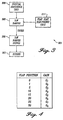
- FIGURE 2 shows a simplified prior art yaw damper 201 for generating a yaw damper command, YDCMD, that controls deflection of the rudder during a turn.
- the YDCMD signal is typically provided to one or more yaw damper servos that actuate the rudder of an aircraft.
- This particular yaw damper 201 is utilized in the Boeing 747-400 aircraft.
- the yaw damper 201 uses data input from inertial reference units located on the aircraft to compute rudder commands (YDCMD) appropriate to existing flight conditions.
- the yaw damper servos then translate the electrical commands from the yaw damper 201 to control hydraulic flow to an actuator piston that moves the rudder of the aircraft.
- Input to the yaw damper 201 includes: N y representing the lateral acceleration of the aircraft; R representing the yaw rate of the aircraft; ⁇ representing the roll angle of the aircraft; and P representing the roll rate of the aircraft.
- N y representing the lateral acceleration of the aircraft
- R representing the yaw rate of the aircraft
- ⁇ representing the roll angle of the aircraft
- P representing the roll rate of the aircraft.
- the lateral acceleration N y is multiplied by a constant K 11 at a first multiplier box 203.
- the output of first multiplier box 203 is then provided to a first summer 205 which sums the signal output from first multiplier box 203 and the output from a second multiplier box 207.
- the second multiplier box 207 receives as input the yaw rate R and multiplies the yaw rate R by a predetermined constant, K 12 .
- the yaw rate R is also provided to a third multiplier box 209 that multiplies the yaw rate R by a predetermined constant N 12 .
- the roll angle ⁇ is provided to a seventh multiplier box 227 which multiplies the roll angle ⁇ by a constant, C.
- the output of the seventh multiplier box 227 is provided to a fourth multiplier box 211 that multiplies the output of seventh multiplier box 227 by a constant N 13 .
- the output of fourth multiplier box 211 is provided to a second summer 213 which adds the output of fourth multiplier box 211 with the output of a fifth multiplier box 215.
- Fifth multiplier box 215 multiplies the roll rate P by a predetermined constant N 14 .
- the output of second summer 213 is provided to a third summer 217 which also receives as an input the output of third multiplier box 209.
- the output of third summer 217 is provided to a fourth summer 219.
- the output of first summer 205 is provided to a first order lag box 221.
- the output of the first order lag box 221 is provided to a sixth multiplier box 223, which multiplies the output of first order lag 221 by a gain factor M.
- the output of sixth multiplier box 223 is also provided to fourth summer 219.
- the output of fourth summer 219 is then provided to a fifth summer 225.
- the output of seventh multiplier box 227 is also provided to a turn coordination gain box 229.
- the turn coordination gain box 229 also receives as input a signal 231 from the air data computer of the aircraft a signal, such as airspeed V TAS (in the case of the Boeing 767) or exterior air pressure Qc (in the case of the Boeing 747).
- a signal such as airspeed V TAS (in the case of the Boeing 767) or exterior air pressure Qc (in the case of the Boeing 747).
- the input from the air data computer is used to calculate a turn coordination gain value that is used to multiply with the output of seventh multiplier 227.
- the calculation of the turn coordination gain in the Boeing 747 is in accordance with FIGURE 1.
- the input 231 provided to the turn coordination gain box 229 is a signal from the flap slat electronic unit (FSEU) which indicates the position of the aircraft flaps.
- FSEU flap slat electronic unit
- the input 231 in the preferred embodiment is flap position.
- the flaps are located on the wings of an aircraft and are extended or retracted to control the amount of lift generated by the wings.
- the position of a flap is typically referred to in degrees.
- the flaps can be placed in one of several discrete degree positions. For example, in the Boeing 777, the flaps may be placed at 1, 5, 10, 15, 20, 25, or 30 degrees extension from the retracted position.
- the yaw damper system 301 of the present invention includes a yaw damper unit 303, a yaw damper servo 305, a rudder 307, an inertial reference unit 309, and a FSEU 311.
- Aircraft motion information is provided by the inertial reference unit 309 to the yaw damper unit 303.
- Flap position information is provided to the yaw damper 303 by the FSEU 311.
- the yaw damper unit 303 receives this information and, in accordance with its calculation techniques, formulates a YDCMD signal to the yaw damper servo 305.
- the yaw damper servo actuates the rudder to the desired deflection.
- the present invention relies on the flap position of the aircraft to determine the turn coordination gain.
- the turn coordination gain box 229 consists of a multiplier and a look up table implemented in a microprocessor.
- the input from seventh multiplier 227 is multiplied by the appropriate turn coordination gain value from the look up table.
- the look up table may be implemented in ROM. Based on the flap position as reported by the FSEU 311, the appropriate turn coordination gain value is used as the multiplier.
- a tabular representation of the look up table is shown in FIGURE 4, with G 1 through G 8 being the possible values of gain.
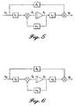
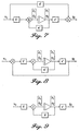
- FIGURES 5-9 illustrate graphically how the turn coordination gains are calculated and the theoretical basis for the calculations.
- optimal turn coordination gain requires a neutrally stable spiral mode after closing the yaw damper loop.
- the gain of the yaw damper must drive the spiral mode of the closed loop system to the origin.
- the gain driving the spiral mode to the origin can be obtained by solving the state equations for the closed loop aircraft system at a steady state turn angle. This process can be derived mathematically as follows:
- FIGURE 5 The block diagram representation of the equations above is shown in FIGURE 5.
- the matrices a 1 , b 1 , c 1 , d 1 represent the aerodynamic model for the particular aircraft that is being modeled.
- the parameter u 1 represents the amount of rudder deflection. It can be appreciated by those skilled in the art that these matrices can be calculated in accordance with known techniques based upon the physical dimensions of the aircraft and the flight parameters of the aircraft. Moreover, the matrices a 1 , b 1 , c 1 , d 1 will be different for different flap positions of the aircraft. This is because when the flap positions of the aircraft change, the aerodynamic characteristics of the aircraft change, thereby changing the matrices that define the behavior of the aircraft.
- the values of a 2 , b 2 , y 2 , c 2 , and d 2 may be obtained from the yaw damper system of the particular aircraft.
- the values of b 2 , c 2 , and d 2 can be obtained from the multipliers shown in FIGURE 2.
- A a' ij + b
- ⁇ r is the amount of rudder needed through roll angle feedback to keep the airplane from being divergent or convergent.
- the values for the matrices a 1 , b 1 , c 1 and d 1 will vary depending upon the operational flight conditions of the aircraft, including flap position. For example, aircraft variations in speed, weight, altitude, flap position and center of gravity will have an influence on the matrices.
- matrices are used that include extreme values of these operational parameters.
- the resulting turn coordination gain used in the look up table is then calculated as the mean of the turn coordination gains calculated using the various extreme matrices. This ensures that the turn coordination gain box 229 has taken into account all possible flight conditions.
- turn coordination gain values were calculated for the Boeing 747-400 aircraft for various flap positions, namely, one, five, ten, and twenty degrees. Note that there are several turn coordination gain values for each flap position. This corresponds to the various extreme operating conditions of the aircraft. In the preferred embodiment, the turn coordination gain used in the look-up table will be the average of the extreme values.
Landscapes
- Engineering & Computer Science (AREA)
- Aviation & Aerospace Engineering (AREA)
- Radar, Positioning & Navigation (AREA)
- Remote Sensing (AREA)
- Physics & Mathematics (AREA)
- General Physics & Mathematics (AREA)
- Automation & Control Theory (AREA)
- Control Of Position, Course, Altitude, Or Attitude Of Moving Bodies (AREA)
- Feedback Control In General (AREA)
- Navigation (AREA)
Applications Claiming Priority (2)
| Application Number | Priority Date | Filing Date | Title |
|---|---|---|---|
| US08/645,616 US5839697A (en) | 1996-05-14 | 1996-05-14 | Method and apparatus for turn coordination gain as a function of flap position |
| US645616 | 1996-05-14 |
Publications (2)
| Publication Number | Publication Date |
|---|---|
| EP0807574A1 true EP0807574A1 (de) | 1997-11-19 |
| EP0807574B1 EP0807574B1 (de) | 2002-07-03 |
Family
ID=24589746
Family Applications (1)
| Application Number | Title | Priority Date | Filing Date |
|---|---|---|---|
| EP97201290A Expired - Lifetime EP0807574B1 (de) | 1996-05-14 | 1997-04-29 | Methode und Vorrichtung zur Verstärkungsanpassung eines Kurvenflugkoordinators in Abhängigkeit von der Landeklappenposition |
Country Status (6)
| Country | Link |
|---|---|
| US (1) | US5839697A (de) |
| EP (1) | EP0807574B1 (de) |
| JP (1) | JP4234797B2 (de) |
| CN (1) | CN1124532C (de) |
| CA (1) | CA2204065C (de) |
| DE (1) | DE69713680T2 (de) |
Families Citing this family (14)
| Publication number | Priority date | Publication date | Assignee | Title |
|---|---|---|---|---|
| US6913226B2 (en) * | 2003-10-30 | 2005-07-05 | The Boeing Company | Methods and systems for redundant control and/or failure detection |
| US7272473B2 (en) * | 2004-09-17 | 2007-09-18 | The Boeing Company | Methods and systems for analyzing system operator coupling susceptibility |
| US7690597B2 (en) * | 2006-07-17 | 2010-04-06 | Eaton Corporation | Flap actuator |
| DE102007045547A1 (de) * | 2007-09-24 | 2009-04-16 | Airbus Deutschland Gmbh | Automatische Steuerung eines Hochauftriebssystems eines Flugzeugs |
| CN102717889A (zh) * | 2012-06-01 | 2012-10-10 | 湖南山河科技股份有限公司 | 轻型飞机襟翼控制方法及装置 |
| JP6289977B2 (ja) * | 2014-03-31 | 2018-03-07 | 三菱重工業株式会社 | 飛しょう体、及び、飛しょう体の動作方法 |
| CN106406096B (zh) * | 2016-10-26 | 2019-04-26 | 北京航空航天大学 | 一种适用于飞行器横侧向机动的耦合利用协调控制方法 |
| CN107688685B (zh) * | 2017-07-03 | 2020-04-21 | 西北工业大学 | 一种局部空间电梯系统系绳内部张力预测方法 |
| CN110239733B (zh) * | 2019-05-29 | 2022-09-20 | 陕西飞机工业(集团)有限公司 | 一种飞机偏航、侧滑时襟翼调整量的计算方法 |
| CN110606192A (zh) * | 2019-10-24 | 2019-12-24 | 中国航空工业集团公司沈阳飞机设计研究所 | 一种飞机前轮转弯控制方法 |
| CN110687924B (zh) * | 2019-11-11 | 2022-11-29 | 朗星无人机系统有限公司 | 一种大中型无人机襟翼控制系统 |
| CN111086646B (zh) * | 2019-12-17 | 2022-11-11 | 西北工业大学 | 一种飞机襟翼操纵系统的状态监测方法及系统 |
| CN114047784B (zh) * | 2021-11-16 | 2024-06-14 | 中国商用飞机有限责任公司 | 飞行器控制方法、装置、飞行器及计算机可读存储介质 |
| CN113885581B (zh) * | 2021-11-24 | 2023-04-11 | 中国商用飞机有限责任公司 | 协调飞行控制方法、装置、电子设备及可读存储介质 |
Citations (3)
| Publication number | Priority date | Publication date | Assignee | Title |
|---|---|---|---|---|
| FR2339920A1 (fr) * | 1976-01-29 | 1977-08-26 | Sperry Rand Corp | Systeme de commande de stabilite selon l'axe des lacets pour engin aerien |
| EP0293018A2 (de) * | 1987-05-28 | 1988-11-30 | The Boeing Company | System zur Modenunterdrückung für Flugzeuge |
| EP0296951A1 (de) * | 1987-06-24 | 1988-12-28 | AEROSPATIALE Société Nationale Industrielle | Roll- und Giersteuerungssystem für ein Luftfahrzeug |
Family Cites Families (19)
| Publication number | Priority date | Publication date | Assignee | Title |
|---|---|---|---|---|
| CA599273A (en) * | 1960-06-07 | J. Gorzelany Frank | Turn control for automatic pilot systems | |
| CA599225A (en) * | 1960-06-07 | C. Owen John | Automatic steering system | |
| US2238300A (en) * | 1938-05-14 | 1941-04-15 | Sperry Gyroscope Co Inc | Airplane automatic pilot with automatic banking |
| US2450907A (en) * | 1944-04-15 | 1948-10-12 | Sperry Corp | Turn control means for an automatic pilot |
| US2585162A (en) * | 1947-09-18 | 1952-02-12 | Bendix Aviat Corp | Coordinated turn controller for automatic pilot systems |
| GB679586A (en) * | 1949-06-23 | 1952-09-17 | Bendix Aviat Corp | Automatic steering system |
| US2883127A (en) * | 1953-06-05 | 1959-04-21 | Bendix Aviat Corp | Turn control for automatic pilot systems |
| GB790272A (en) * | 1956-02-13 | 1958-02-05 | Sperry Rand Corp | Automatic control systems for aircraft |
| GB1112379A (en) * | 1964-08-10 | 1968-05-01 | Elliott Brothers London Ltd | Aircraft turn entry |
| DE1481551B2 (de) * | 1967-02-02 | 1975-03-27 | Fluggeraetewerk Bodensee Gmbh, 7770 Ueberlingen | Kurvenflugregler für Flugzeuge |
| US3618879A (en) * | 1969-08-14 | 1971-11-09 | Bell Aerospace Corp | Pitch/roll to yaw flight coordinator |
| US3777242A (en) * | 1972-12-21 | 1973-12-04 | Collins Radio Co | Turn coordination control with dead space and limited washout |
| US4479620A (en) * | 1978-07-13 | 1984-10-30 | The Boeing Company | Wing load alleviation system using tabbed allerons |
| US4676460A (en) * | 1984-11-28 | 1987-06-30 | The Boeing Company | Longitudinal stability augmentation system and method |
| EP0377231A3 (de) * | 1989-01-06 | 1990-08-08 | The Boeing Company | Methode und Vorrichtung zur Verringerung falscher Windscherungs-Alarme |
| US5089968A (en) * | 1990-01-26 | 1992-02-18 | The Boeing Company | Ground effects compensated real time aircraft body angle of attack estimation |
| US5050086A (en) * | 1990-04-30 | 1991-09-17 | The Boeing Company | Aircraft lateral-directional control system |
| FR2668750B1 (fr) * | 1990-11-06 | 1993-01-22 | Aerospatiale | Systeme pour la commande integree en profondeur et en poussee d'un aeronef. |
| US5452865A (en) * | 1993-06-28 | 1995-09-26 | The Boeing Company | Aircraft frequency adaptive modal suppression system |
-
1996
- 1996-05-14 US US08/645,616 patent/US5839697A/en not_active Expired - Lifetime
-
1997
- 1997-04-29 DE DE69713680T patent/DE69713680T2/de not_active Expired - Lifetime
- 1997-04-29 EP EP97201290A patent/EP0807574B1/de not_active Expired - Lifetime
- 1997-04-30 CA CA002204065A patent/CA2204065C/en not_active Expired - Lifetime
- 1997-05-12 JP JP12080597A patent/JP4234797B2/ja not_active Expired - Lifetime
- 1997-05-13 CN CN97111159.6A patent/CN1124532C/zh not_active Expired - Lifetime
Patent Citations (4)
| Publication number | Priority date | Publication date | Assignee | Title |
|---|---|---|---|---|
| FR2339920A1 (fr) * | 1976-01-29 | 1977-08-26 | Sperry Rand Corp | Systeme de commande de stabilite selon l'axe des lacets pour engin aerien |
| EP0293018A2 (de) * | 1987-05-28 | 1988-11-30 | The Boeing Company | System zur Modenunterdrückung für Flugzeuge |
| US5072893A (en) * | 1987-05-28 | 1991-12-17 | The Boeing Company | Aircraft modal suppression system |
| EP0296951A1 (de) * | 1987-06-24 | 1988-12-28 | AEROSPATIALE Société Nationale Industrielle | Roll- und Giersteuerungssystem für ein Luftfahrzeug |
Non-Patent Citations (1)
| Title |
|---|
| PETER M. THOMPSON ET AL.: "H ROBUST CONTROL SYNTHESIS FOR A FIGHTER PERFORMING A COORDINATED BANK TURN", PROCEEDINGS OF THE 29TH IEEE CONFERENCE ON DECISION AND CONTROL, vol. 6, 5 December 1990 (1990-12-05) - 7 December 1990 (1990-12-07), HILTON HAWAIIAN VILLAGE, HONOLULU, HAWAII, pages 3362 - 3366, XP000207313 * |
Also Published As
| Publication number | Publication date |
|---|---|
| CA2204065C (en) | 2005-09-27 |
| JPH1053198A (ja) | 1998-02-24 |
| CN1124532C (zh) | 2003-10-15 |
| US5839697A (en) | 1998-11-24 |
| CN1166638A (zh) | 1997-12-03 |
| DE69713680T2 (de) | 2002-10-17 |
| JP4234797B2 (ja) | 2009-03-04 |
| EP0807574B1 (de) | 2002-07-03 |
| DE69713680D1 (de) | 2002-08-08 |
| CA2204065A1 (en) | 1997-11-14 |
Similar Documents
| Publication | Publication Date | Title |
|---|---|---|
| US4094479A (en) | Side slip angle command SCAS for aircraft | |
| CA1253835A (en) | Automatic camber control | |
| US10935985B2 (en) | Pitch and thrust control for tilt-rotor aircraft | |
| EP0807574B1 (de) | Methode und Vorrichtung zur Verstärkungsanpassung eines Kurvenflugkoordinators in Abhängigkeit von der Landeklappenposition | |
| US6735500B2 (en) | Method, system, and computer program product for tactile cueing flight control | |
| US5079711A (en) | Aircraft high altitude vertical flight path and speed control system | |
| JP3308532B2 (ja) | 回転翼機用の高速旋回調整方法 | |
| US20030088341A1 (en) | Method and computer program product for controlling the actuators of an aerodynamic vehicle | |
| Cook et al. | A robust uniform control approach for vtol aircraft | |
| EP1429220B2 (de) | Verfahren und Computerprogrammprodukt zur Steuerung von Steuerflächen für ein aerodynamisches Fahrzeug | |
| Park | Control and guidance for precision deep stall landing | |
| EP3561631B1 (de) | Neigungs- und schubregelung für verbundflugzeuge | |
| Surmann et al. | Gain Design of an INDI-based Controller for a Conceptual eVTOL in a Nonlinear Simulation Environment | |
| Kim et al. | Trajectory tracking controller design using neural networks for a tiltrotor unmanned aerial vehicle | |
| Berger et al. | Flight control design and simulation handling qualities assessment of high-speed rotorcraft | |
| Sahasrabudhe et al. | Simulation Investigation of a Comprehensive Collective‐Axis Tactile Cueing System | |
| Sahani et al. | Command limiting for full-envelope guidance and control of rotorcraft | |
| Gilyard | In-flight transport performance optimization: An experimental flight research program and an operational scenario | |
| Adams et al. | Full envelope multivariable control law synthesis for a high-performance test aircraft | |
| Sturgeon et al. | A mathematical model of the CH-53 helicopter | |
| Gripp et al. | Practical application of Open Loop Onset Point Criterion to predict actuator rate saturation PIO in fly-by-wire aircraft | |
| Saetti et al. | Dynamic inversion-based flare control law for autonomous helicopter autorotation | |
| Griswold | Integrated flight and propulsion control system design for a business jet | |
| Reitz | Control System Development for Autonomous Aerobatic Maneuvering with a Fixed-Wing Aircraft | |
| Kim et al. | Flying qualities evaluation of an unmanned aircraft using JSBSim |
Legal Events
| Date | Code | Title | Description |
|---|---|---|---|
| PUAI | Public reference made under article 153(3) epc to a published international application that has entered the european phase |
Free format text: ORIGINAL CODE: 0009012 |
|
| AK | Designated contracting states |
Kind code of ref document: A1 Designated state(s): DE FR GB |
|
| 17P | Request for examination filed |
Effective date: 19980429 |
|
| GRAG | Despatch of communication of intention to grant |
Free format text: ORIGINAL CODE: EPIDOS AGRA |
|
| 17Q | First examination report despatched |
Effective date: 20010820 |
|
| GRAG | Despatch of communication of intention to grant |
Free format text: ORIGINAL CODE: EPIDOS AGRA |
|
| GRAH | Despatch of communication of intention to grant a patent |
Free format text: ORIGINAL CODE: EPIDOS IGRA |
|
| GRAH | Despatch of communication of intention to grant a patent |
Free format text: ORIGINAL CODE: EPIDOS IGRA |
|
| GRAA | (expected) grant |
Free format text: ORIGINAL CODE: 0009210 |
|
| AK | Designated contracting states |
Kind code of ref document: B1 Designated state(s): DE FR GB |
|
| REF | Corresponds to: |
Ref document number: 69713680 Country of ref document: DE Date of ref document: 20020808 |
|
| ET | Fr: translation filed | ||
| PLBE | No opposition filed within time limit |
Free format text: ORIGINAL CODE: 0009261 |
|
| 26N | No opposition filed |
Effective date: 20030404 |
|
| REG | Reference to a national code |
Ref country code: FR Ref legal event code: PLFP Year of fee payment: 20 |
|
| PGFP | Annual fee paid to national office [announced via postgrant information from national office to epo] |
Ref country code: GB Payment date: 20160427 Year of fee payment: 20 Ref country code: DE Payment date: 20160427 Year of fee payment: 20 |
|
| PGFP | Annual fee paid to national office [announced via postgrant information from national office to epo] |
Ref country code: FR Payment date: 20160425 Year of fee payment: 20 |
|
| REG | Reference to a national code |
Ref country code: DE Ref legal event code: R071 Ref document number: 69713680 Country of ref document: DE |
|
| REG | Reference to a national code |
Ref country code: GB Ref legal event code: PE20 Expiry date: 20170428 |
|
| PG25 | Lapsed in a contracting state [announced via postgrant information from national office to epo] |
Ref country code: GB Free format text: LAPSE BECAUSE OF EXPIRATION OF PROTECTION Effective date: 20170428 |