EP0807571A1 - Druckregler - Google Patents
Druckregler Download PDFInfo
- Publication number
- EP0807571A1 EP0807571A1 EP97107421A EP97107421A EP0807571A1 EP 0807571 A1 EP0807571 A1 EP 0807571A1 EP 97107421 A EP97107421 A EP 97107421A EP 97107421 A EP97107421 A EP 97107421A EP 0807571 A1 EP0807571 A1 EP 0807571A1
- Authority
- EP
- European Patent Office
- Prior art keywords
- pressure regulator
- shutoff element
- regulator according
- chamber
- valve seat
- Prior art date
- Legal status (The legal status is an assumption and is not a legal conclusion. Google has not performed a legal analysis and makes no representation as to the accuracy of the status listed.)
- Granted
Links
- 239000000463 material Substances 0.000 claims abstract description 11
- 239000007789 gas Substances 0.000 claims abstract description 8
- 239000007779 soft material Substances 0.000 claims abstract description 6
- 239000000203 mixture Substances 0.000 claims abstract description 5
- 239000010979 ruby Substances 0.000 claims description 4
- 229910001750 ruby Inorganic materials 0.000 claims description 4
- 229920002635 polyurethane Polymers 0.000 claims description 3
- 239000004814 polyurethane Substances 0.000 claims description 3
- 239000004677 Nylon Substances 0.000 claims description 2
- 229910000831 Steel Inorganic materials 0.000 claims description 2
- 239000004809 Teflon Substances 0.000 claims description 2
- 229920006362 Teflon® Polymers 0.000 claims description 2
- 229910052593 corundum Inorganic materials 0.000 claims description 2
- 239000010431 corundum Substances 0.000 claims description 2
- 229920001778 nylon Polymers 0.000 claims description 2
- 229920000642 polymer Polymers 0.000 claims description 2
- 239000010959 steel Substances 0.000 claims description 2
- 239000004575 stone Substances 0.000 claims description 2
- 229920003051 synthetic elastomer Polymers 0.000 claims description 2
- 239000005061 synthetic rubber Substances 0.000 claims description 2
- 229910010293 ceramic material Inorganic materials 0.000 claims 1
- 229920001971 elastomer Polymers 0.000 description 3
- 239000012528 membrane Substances 0.000 description 3
- 239000005060 rubber Substances 0.000 description 3
- 238000007789 sealing Methods 0.000 description 3
- 239000000919 ceramic Substances 0.000 description 2
- 239000002184 metal Substances 0.000 description 2
- 239000012530 fluid Substances 0.000 description 1
- 238000007654 immersion Methods 0.000 description 1
- 238000003780 insertion Methods 0.000 description 1
- 230000037431 insertion Effects 0.000 description 1
- 239000007788 liquid Substances 0.000 description 1
- 239000007769 metal material Substances 0.000 description 1
- 230000029058 respiratory gaseous exchange Effects 0.000 description 1
- 229910052594 sapphire Inorganic materials 0.000 description 1
- 239000010980 sapphire Substances 0.000 description 1
Images

Classifications
-
- B—PERFORMING OPERATIONS; TRANSPORTING
- B63—SHIPS OR OTHER WATERBORNE VESSELS; RELATED EQUIPMENT
- B63C—LAUNCHING, HAULING-OUT, OR DRY-DOCKING OF VESSELS; LIFE-SAVING IN WATER; EQUIPMENT FOR DWELLING OR WORKING UNDER WATER; MEANS FOR SALVAGING OR SEARCHING FOR UNDERWATER OBJECTS
- B63C11/00—Equipment for dwelling or working underwater; Means for searching for underwater objects
- B63C11/02—Divers' equipment
- B63C11/18—Air supply
- B63C11/22—Air supply carried by diver
- B63C11/2209—First-stage regulators
-
- G—PHYSICS
- G05—CONTROLLING; REGULATING
- G05D—SYSTEMS FOR CONTROLLING OR REGULATING NON-ELECTRIC VARIABLES
- G05D16/00—Control of fluid pressure
- G05D16/04—Control of fluid pressure without auxiliary power
- G05D16/06—Control of fluid pressure without auxiliary power the sensing element being a flexible membrane, yielding to pressure, e.g. diaphragm, bellows, capsule
- G05D16/063—Control of fluid pressure without auxiliary power the sensing element being a flexible membrane, yielding to pressure, e.g. diaphragm, bellows, capsule the sensing element being a membrane
- G05D16/0644—Control of fluid pressure without auxiliary power the sensing element being a flexible membrane, yielding to pressure, e.g. diaphragm, bellows, capsule the sensing element being a membrane the membrane acting directly on the obturator
- G05D16/0663—Control of fluid pressure without auxiliary power the sensing element being a flexible membrane, yielding to pressure, e.g. diaphragm, bellows, capsule the sensing element being a membrane the membrane acting directly on the obturator using a spring-loaded membrane with a spring-loaded slideable obturator
-
- Y—GENERAL TAGGING OF NEW TECHNOLOGICAL DEVELOPMENTS; GENERAL TAGGING OF CROSS-SECTIONAL TECHNOLOGIES SPANNING OVER SEVERAL SECTIONS OF THE IPC; TECHNICAL SUBJECTS COVERED BY FORMER USPC CROSS-REFERENCE ART COLLECTIONS [XRACs] AND DIGESTS
- Y10—TECHNICAL SUBJECTS COVERED BY FORMER USPC
- Y10T—TECHNICAL SUBJECTS COVERED BY FORMER US CLASSIFICATION
- Y10T137/00—Fluid handling
- Y10T137/1842—Ambient condition change responsive
- Y10T137/2036—Underwater
-
- Y—GENERAL TAGGING OF NEW TECHNOLOGICAL DEVELOPMENTS; GENERAL TAGGING OF CROSS-SECTIONAL TECHNOLOGIES SPANNING OVER SEVERAL SECTIONS OF THE IPC; TECHNICAL SUBJECTS COVERED BY FORMER USPC CROSS-REFERENCE ART COLLECTIONS [XRACs] AND DIGESTS
- Y10—TECHNICAL SUBJECTS COVERED BY FORMER USPC
- Y10T—TECHNICAL SUBJECTS COVERED BY FORMER US CLASSIFICATION
- Y10T137/00—Fluid handling
- Y10T137/7722—Line condition change responsive valves
- Y10T137/7781—With separate connected fluid reactor surface
- Y10T137/7793—With opening bias [e.g., pressure regulator]
- Y10T137/7809—Reactor surface separated by apertured partition
- Y10T137/782—Reactor surface is diaphragm
- Y10T137/7821—With valve closing bias
-
- Y—GENERAL TAGGING OF NEW TECHNOLOGICAL DEVELOPMENTS; GENERAL TAGGING OF CROSS-SECTIONAL TECHNOLOGIES SPANNING OVER SEVERAL SECTIONS OF THE IPC; TECHNICAL SUBJECTS COVERED BY FORMER USPC CROSS-REFERENCE ART COLLECTIONS [XRACs] AND DIGESTS
- Y10—TECHNICAL SUBJECTS COVERED BY FORMER USPC
- Y10T—TECHNICAL SUBJECTS COVERED BY FORMER US CLASSIFICATION
- Y10T137/00—Fluid handling
- Y10T137/7722—Line condition change responsive valves
- Y10T137/7781—With separate connected fluid reactor surface
- Y10T137/7793—With opening bias [e.g., pressure regulator]
- Y10T137/7822—Reactor surface closes chamber
- Y10T137/7823—Valve head in inlet chamber
- Y10T137/7826—With valve closing bias
Definitions
- the present invention relates to a two-stage aqualung.
- the present invention relates to a pressure regulator, for the first reduction stage of a two-stage aqualung, of the type comprising a first stage that has a reduction chamber communicating by means of a supply valve with an inlet passage for the air (or for a mixture of breathable gases) at high pressure and with an outlet connected, by means of a connecting passage, to a second reduction stage.
- the first reduction stage is provided with a flexing chamber for an impermeable and elastically deformable diaphragm which operates the control member of the shutoff element of the supply valve.
- Said flexing chamber communicates with the connecting passage leading to the second reducing stage and is sealed off from a chamber communicating with the external environment by the aforementioned diaphragm, which can be subjected to an elastic preloading tending to open the shutoff element of the supply valve, in such a way that the pressure of the external environment and the elastic preloading cause this membrane to flex in the appropriate direction to open the supply valve during inhalation.
- the said tighness is always uncertain, because normally to obtain a gas-tight seal a soft element, consisting of rubber or some similar material, is used cooperating with a rigid element, generally made of metal, with one of the said elements being mobile and being pushed costantly against the fixed element by a spring.
- the soft element constitutes the mobile one and the rigid element is a seat having a suitable shape almost always rather sharp.
- check valves are known provided with a movable ball valve element cooperating with a fixed seat element, in which both ball and seat are made of ceramics or the like materials. Said valves however have been used in aqualung pressure regulators. So, for instance, the US Patent N° 5 002 662 by Ledtje is concerned with such a ball valve, but the said patent relates to a check valve for liquids, and not to a aqualung pressure regulator, that is the said patent is concerned with a technical problem which is completely different from the problem of the present invention, or also the US Patent N° 4 228 821 by Stark which is concerned with a valve for compressed gases comprising a ball and valve seat both made of hard material such as sapphire or ruby.
- check valves for high-pressure fluids are known, like the one shown in US Patent N° 3 620 251 by Bowen, according to which there are a mobile and a fixed valve element, both made of metal, in which the fixed element is not a ball.
- the mobile element of the valve is formed by a semisphere (which may be made integral with the mobile element or may be tipped to said element by setting) which may be made of ruby, ceramics or the like hard materials, which cooperates with a valve seat made of a comparatively soft material, like rubber or the like.
- valve of the regulator according to the invention there are no sharp surfaces which may cause the tearing off of the soft element of the valve. This means that the above mentioned phenomena of the violent self-delivery at the second stage of the prior art regulators is completely avoided. It is to be noted that the said phenomena of self-delivery, which in a regulator which is not intended for underwater use may be also considered not serious, in a regulator for underwater use it may be fatal. This means that the regulator according to the invention offers a safety which may be not obtained with the regulators for underwater use of prior art.
- the pressure regulator for the first reduction stage of a two-stage aqualung, that forms the subject of the present invention, comprising a reduction chamber that communicates, by means of a supply valve comprising a valve seat and a guided shutoff element, with an inlet passage for the air or a mixture of breathable gases at high pressure and with a connecting passage leading to a second reduction stage, said first reduction stage being provided with a flexing chamber for an impermeable and elastically deformable diaphragm operating a cylindrical member that controls the shutoff element of the supply valve, said cylindrical member extending through a communication passage from the chamber to the chamber, which regulator is characterized in that the seat of said supply valve is planar and is made of a relatively soft material, and said shutoff element, which enters the channel of the valve seat, is conical- or hemispherical-sectioned and is made of a hard material.
- the first reducing stage, of a two-stage aqualung, forming the subject of the present invention comprises a body 1 in which a reduction chamber 2 is formed.
- the reduction chamber 2 communicates with an inlet passage 4 whose free end can be sealed tight by a plug 6 with a loading spring 8 that closes the first stage.
- the supply valve comprising the shutoff element 10 in the inlet passage 4 and the valve seat 12 communicating with the inlet passage 2.
- valve shutoff element 10 is elastically preloaded against the valve seat 12 by a spring 14, so that it sits stably in the closed position and is pushed on to the valve seat 12, sealing in the high-pressure air present in the inlet passage 4.
- the spring 14 is supported on a guide bush 16 and reacts against the plug 6.
- the shutoff element 10 is guided so that it can move coaxially in a central guide hole through the guide bush 16 and is supported on a coaxial control rod 18 which in turn is guided so as to be able to move axially through the reduction chamber 2.
- the other end of the control rod 18 carries a thrust disc 20 that projects into a flexing chamber 22.
- Said thrust disc 20 is designed to act on an impermeable and elastically flexible diaphragm 24 which separates the flexing chamber 22 from a chamber 26 communicating with the external environment through a hole 28.
- a preloading spring 30 acting on the diaphragm 24 and positioned between said membrane and the opposite wall of the chamber 26. Its side facing the diaphragm 24 also carries a thrust disc 32.
- the reduction chamber 2 communicates directly with a passage 34 to which is connected a hose leading to the second reduction stage (not shown). Downstream of the passage 34, a passage 36 connects the passage 34 with the flexing chamber 11.
- the mouth 38 Connected to the abovementioned inlet passage 4 is the mouth 38, fitted with a filter 40, through which the compressed air enters before it is expanded in said first stage.
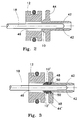
- FIGs 2 and 3 Illustrated in Figures 2 and 3 according to the present invention are two embodiments for the supply valve of Figure 1.
- the shutoff element 10 which is bored centrally and longitudinally for the insertion of the control rod 18, is conical- or hemispherical-sectioned and is carried by a coaxial disc 44 having a bored leg through which said control rod passes and having a shoulder 42 for its rear bearing surface.
- This shutoff element enters a channel 46 present inside the valve seat 12, which is made of a relatively soft material and communicates with the abovementioned inlet passage 4.
- the mouth of the valve seat 12 is slightly flared to assist the entry into it of the shutoff element 10.
- an embodiment of the supply valve comprises the shutoff element 10, made of a hard metallic material, made in one piece with said disc 44.
- FIG 3 another embodiment of the valve has the shutoff element 10' set in a seat 48 in the disc 44' and isolated by the O ring 50.
- Said shutoff element is made of ruby and is basically spherical or hemispherical.
- the shutoff element 10' may advantageously be made of steel, or of a hard stone, such as one of the varieties of corundum or the like, and the valve seat 12 is advantageously made of an engineering polymer, such as teflon, nylon, polyurethane, synthetic rubber or the like.
- suction applied through the passage 34 creates a pressure drop in the chamber 2; this pressure drop causes the diaphragm 24, and consequently, via the thrust disc 20, the control rod 18 of the supply valve 10, 12, to move.
- the shutoff element 10 or 10' moves, it opens the channel 46 of the valve seat 12 allowing air to flow from the mouth 38 through the filter 40 and passage 4 to the chamber 2 and thence to the passage 34, from where the air passes into the second stage (not illustrated).
- the spring 14 moves the shutoff element 10 back to the rest position, i.e. back in the passage 46 of the valve seat 12, thereby shutting it off.
- the shutoff element is structured in such a way that its spherical or conical head enters the passage of the valve seat.
- This system avoids leakages of air caused by valve wear because even if the edge of the channel of the valve seat is rounded by wear over time, the sphere or cone will still close the channel completely and therefore ensure leaktightness.
- the material advantageously used for the sphere is a hard material that ensures that the sphere has the right strength and has an extremely smooth surface.
- the valve seat being made of a soft material, will ensure a snug fit of the shutoff sphere. This system makes complete closure of the valve possible even if slight eccentricities develop of either the valve seat or the shutoff element.
- the spring that ensures the valve is closed by pushing on the shutoff element does not require a large load as in known aqualungs, in which a considerable force is necessary.
- this spring has only to keep the surface of the shutoff sphere in contact with the valve seat channel to guarantee complete and reliable closure of the valve.
Landscapes
- Engineering & Computer Science (AREA)
- Physics & Mathematics (AREA)
- General Health & Medical Sciences (AREA)
- General Physics & Mathematics (AREA)
- Automation & Control Theory (AREA)
- Health & Medical Sciences (AREA)
- Fluid Mechanics (AREA)
- Pulmonology (AREA)
- Mechanical Engineering (AREA)
- Ocean & Marine Engineering (AREA)
- Control Of Fluid Pressure (AREA)
- Check Valves (AREA)
- Secondary Cells (AREA)
Applications Claiming Priority (2)
| Application Number | Priority Date | Filing Date | Title |
|---|---|---|---|
| ITGE960043 | 1996-05-16 | ||
| IT96GE000043A IT1287785B1 (it) | 1996-05-16 | 1996-05-16 | Riduttore di pressione, per il primo stadio di riduzione degli autorespiratori subacquei bistadio. |
Publications (2)
| Publication Number | Publication Date |
|---|---|
| EP0807571A1 true EP0807571A1 (de) | 1997-11-19 |
| EP0807571B1 EP0807571B1 (de) | 2001-10-04 |
Family
ID=11354900
Family Applications (1)
| Application Number | Title | Priority Date | Filing Date |
|---|---|---|---|
| EP97107421A Expired - Lifetime EP0807571B1 (de) | 1996-05-16 | 1997-05-06 | Druckregler |
Country Status (5)
| Country | Link |
|---|---|
| US (1) | US5810041A (de) |
| EP (1) | EP0807571B1 (de) |
| JP (1) | JP3907784B2 (de) |
| DE (1) | DE69707052T2 (de) |
| IT (1) | IT1287785B1 (de) |
Cited By (12)
| Publication number | Priority date | Publication date | Assignee | Title |
|---|---|---|---|---|
| DE19812376A1 (de) * | 1998-03-20 | 1999-09-23 | Norbert Stoffer | Armatur für Preßluftflaschen |
| FR2792388A1 (fr) * | 1999-04-16 | 2000-10-20 | R G S A S Di Rosaria Galli & C | Clapet flottant pour reducteur de pression equilibre, particulierement pour hautes pressions, et reducteur de pression comprenant un tel clapet |
| WO2003033076A1 (en) * | 2001-10-18 | 2003-04-24 | Poseidon Industri Ab | Balanced valve device and breathing apparatus comprising such valve device |
| WO2004005131A3 (en) * | 2002-07-05 | 2004-09-23 | Shane S Taylor | Gas valve |
| US6901958B2 (en) | 2001-06-01 | 2005-06-07 | Shane S. Taylor | Fluid flow control valve |
| FR2878984A1 (fr) * | 2004-12-07 | 2006-06-09 | R G S A S Di Rosaria Galli & C | Reducteur de pression equilibre |
| FR2878985A1 (fr) * | 2004-12-07 | 2006-06-09 | R G S A S Di Rosaria Galli & C | Reducteur de pression equilibre |
| US7185674B2 (en) | 2001-06-01 | 2007-03-06 | Taylor Shane S | Fluid flow control valve |
| EP1531124A3 (de) * | 2003-11-14 | 2007-04-04 | MARES S.p.A. | Erste Druckreglerstufe für ein zweistufiges Unterwasseratemgerät |
| EP3398848A1 (de) | 2017-05-04 | 2018-11-07 | Mares S.p.A. | Erste stufe eines reglers für zweistufige unterwasseratemschutzvorrichtungen |
| CN113167395A (zh) * | 2018-08-13 | 2021-07-23 | 普罗塞夫运营有限责任公司 | 具有压配合插入件的阀 |
| IT202000008914A1 (it) * | 2020-04-24 | 2021-10-24 | Mares Spa | Dispositivo regolatore di pressione con azionamento a soglia |
Families Citing this family (12)
| Publication number | Priority date | Publication date | Assignee | Title |
|---|---|---|---|---|
| US6698715B2 (en) | 1999-12-15 | 2004-03-02 | University Of Alabama | Valve having ceramic components and associated fabrication method |
| US6460559B2 (en) | 1999-12-15 | 2002-10-08 | University Of Alabama In Huntsville | Valve having ceramic components and associated fabrication method |
| DK200100281A (da) * | 2001-02-21 | 2002-08-22 | Flowcon Int As | Membranventil med reguleringsmiddel |
| DE20310832U1 (de) * | 2003-07-14 | 2004-11-18 | Nordson Corporation, Westlake | Druckregler |
| BRPI0306282B8 (pt) * | 2003-12-26 | 2021-06-22 | Intermed Equipamento Medico Hospitalar Ltda | sistema de ventilação em aparelho respiratório |
| ITSV20050009A1 (it) * | 2005-03-15 | 2006-09-16 | Scubapro Europ | Primo stadio di regolazione di pressione per un dispositivo respiratore subacqueo a doppio stadio |
| FR2909635B1 (fr) * | 2006-12-12 | 2009-03-06 | Jean Michel Onofri | Dispositif de flottabilite reglable |
| DE102008005492B3 (de) * | 2008-01-22 | 2009-11-12 | Dürr Systems GmbH | Druckstellglied, insbesondere Farbdruckregler oder Beschichtungsmittelventil |
| CN103615582B (zh) * | 2013-12-04 | 2017-01-04 | 沈阳航天新光集团有限公司 | 减压活门 |
| ES2959679T3 (es) * | 2015-04-03 | 2024-02-27 | Turboden Spa | Turbina multietapa preferiblemente para plantas de ciclo Rankine orgánico ORC |
| CN106334280B (zh) | 2015-07-15 | 2019-01-15 | 梅思安(苏州)安全设备研发有限公司 | 压强调节器组件 |
| EP3187758B1 (de) * | 2016-01-04 | 2019-04-03 | Danfoss A/S | Kapsel für ein ventil und ventil |
Citations (6)
| Publication number | Priority date | Publication date | Assignee | Title |
|---|---|---|---|---|
| US2758596A (en) * | 1954-05-24 | 1956-08-14 | Scott Aviation Corp | Portable breathing apparatus of the demand type |
| FR1305095A (fr) * | 1961-11-08 | 1962-09-28 | Normalair Ltd | Détendeur à soupape de sûreté incorporée |
| US3620251A (en) * | 1970-01-21 | 1971-11-16 | Duriron Co | Valves |
| US4228821A (en) * | 1978-06-07 | 1980-10-21 | Saphirwerk Industrieprodukte Ag | Gas-tight ball valve |
| US5002662A (en) * | 1988-09-07 | 1991-03-26 | Spectra-Physics, Inc. | Check valve |
| EP0531195A1 (de) * | 1991-09-03 | 1993-03-10 | U.S. DIVERS Co., Inc. | Regelbarer Hochdrucksregulator für Taucher |
Family Cites Families (5)
| Publication number | Priority date | Publication date | Assignee | Title |
|---|---|---|---|---|
| CA509117A (en) * | 1955-01-11 | J. Jacobsson Wilgot | Gas pressure regulator resistant to hum | |
| US2768643A (en) * | 1951-06-14 | 1956-10-30 | Union Carbide & Carbon Corp | Regulator for oxygen and other gases |
| ES404538A1 (es) * | 1972-07-05 | 1975-06-16 | Nemrod Metzeler Sa | Mejoras introducidas en la fabricacion de manorreductores de depresion para buceo. |
| EP0328696B1 (de) * | 1988-02-13 | 1990-12-12 | Hewlett-Packard GmbH | Ventileinheit |
| IT1263482B (it) * | 1993-12-17 | 1996-08-05 | Vitaldado S P A Ab | Riduttore di pressione per primo stadio di autorespiratori bistadio. |
-
1996
- 1996-05-16 IT IT96GE000043A patent/IT1287785B1/it active IP Right Grant
-
1997
- 1997-05-06 DE DE69707052T patent/DE69707052T2/de not_active Expired - Fee Related
- 1997-05-06 US US08/851,615 patent/US5810041A/en not_active Expired - Fee Related
- 1997-05-06 EP EP97107421A patent/EP0807571B1/de not_active Expired - Lifetime
- 1997-05-15 JP JP13910897A patent/JP3907784B2/ja not_active Expired - Fee Related
Patent Citations (6)
| Publication number | Priority date | Publication date | Assignee | Title |
|---|---|---|---|---|
| US2758596A (en) * | 1954-05-24 | 1956-08-14 | Scott Aviation Corp | Portable breathing apparatus of the demand type |
| FR1305095A (fr) * | 1961-11-08 | 1962-09-28 | Normalair Ltd | Détendeur à soupape de sûreté incorporée |
| US3620251A (en) * | 1970-01-21 | 1971-11-16 | Duriron Co | Valves |
| US4228821A (en) * | 1978-06-07 | 1980-10-21 | Saphirwerk Industrieprodukte Ag | Gas-tight ball valve |
| US5002662A (en) * | 1988-09-07 | 1991-03-26 | Spectra-Physics, Inc. | Check valve |
| EP0531195A1 (de) * | 1991-09-03 | 1993-03-10 | U.S. DIVERS Co., Inc. | Regelbarer Hochdrucksregulator für Taucher |
Cited By (19)
| Publication number | Priority date | Publication date | Assignee | Title |
|---|---|---|---|---|
| DE19812376A1 (de) * | 1998-03-20 | 1999-09-23 | Norbert Stoffer | Armatur für Preßluftflaschen |
| FR2792388A1 (fr) * | 1999-04-16 | 2000-10-20 | R G S A S Di Rosaria Galli & C | Clapet flottant pour reducteur de pression equilibre, particulierement pour hautes pressions, et reducteur de pression comprenant un tel clapet |
| US7185674B2 (en) | 2001-06-01 | 2007-03-06 | Taylor Shane S | Fluid flow control valve |
| US7341075B2 (en) | 2001-06-01 | 2008-03-11 | Taylor Shane S | Fluid flow control valve |
| US6901958B2 (en) | 2001-06-01 | 2005-06-07 | Shane S. Taylor | Fluid flow control valve |
| US8622081B2 (en) | 2001-06-01 | 2014-01-07 | Shane S. Taylor | Fluid flow control valve |
| US7686017B2 (en) | 2001-06-01 | 2010-03-30 | Taylor Shane S | Fluid flow control valve |
| CN100415323C (zh) * | 2001-10-18 | 2008-09-03 | 海神工业公司 | 平衡阀装置以及包含此平衡阀的呼吸装置 |
| WO2003033076A1 (en) * | 2001-10-18 | 2003-04-24 | Poseidon Industri Ab | Balanced valve device and breathing apparatus comprising such valve device |
| US7089940B2 (en) | 2001-10-18 | 2006-08-15 | Poseidon Industri Ab | Balanced valve device and breathing apparatus comprising such valve device |
| WO2004005131A3 (en) * | 2002-07-05 | 2004-09-23 | Shane S Taylor | Gas valve |
| US7921872B2 (en) | 2002-07-05 | 2011-04-12 | Taylor Shane S | Gas valve |
| EP1531124A3 (de) * | 2003-11-14 | 2007-04-04 | MARES S.p.A. | Erste Druckreglerstufe für ein zweistufiges Unterwasseratemgerät |
| FR2878985A1 (fr) * | 2004-12-07 | 2006-06-09 | R G S A S Di Rosaria Galli & C | Reducteur de pression equilibre |
| FR2878984A1 (fr) * | 2004-12-07 | 2006-06-09 | R G S A S Di Rosaria Galli & C | Reducteur de pression equilibre |
| EP3398848A1 (de) | 2017-05-04 | 2018-11-07 | Mares S.p.A. | Erste stufe eines reglers für zweistufige unterwasseratemschutzvorrichtungen |
| CN113167395A (zh) * | 2018-08-13 | 2021-07-23 | 普罗塞夫运营有限责任公司 | 具有压配合插入件的阀 |
| IT202000008914A1 (it) * | 2020-04-24 | 2021-10-24 | Mares Spa | Dispositivo regolatore di pressione con azionamento a soglia |
| EP3904198A1 (de) * | 2020-04-24 | 2021-11-03 | Mares S.p.A. | Reduzierventil der ersten stufe eines zweistufigen atemreglers für den einsatz beim tauchen |
Also Published As
| Publication number | Publication date |
|---|---|
| ITGE960043A0 (it) | 1996-05-16 |
| ITGE960043A1 (it) | 1997-11-16 |
| IT1287785B1 (it) | 1998-08-18 |
| DE69707052T2 (de) | 2002-06-20 |
| DE69707052D1 (de) | 2001-11-08 |
| EP0807571B1 (de) | 2001-10-04 |
| US5810041A (en) | 1998-09-22 |
| JPH1063344A (ja) | 1998-03-06 |
| JP3907784B2 (ja) | 2007-04-18 |
Similar Documents
| Publication | Publication Date | Title |
|---|---|---|
| EP0807571B1 (de) | Druckregler | |
| US4730635A (en) | Valve and method | |
| EP2240715B1 (de) | Regeldrosselventil und dichtung dafür | |
| US6601609B2 (en) | Fluid flow control valve | |
| US7686017B2 (en) | Fluid flow control valve | |
| US5762086A (en) | Apparatus for delivering process gas for making semiconductors and method of using same | |
| US5332000A (en) | Low pressure sensitive valve | |
| JPS61175376A (ja) | ロールダイアフラム調整弁 | |
| KR20200112711A (ko) | 유체 제어 밸브 | |
| US10914396B2 (en) | Electro-pneumatic valve with pressurized container | |
| CA2068105A1 (en) | Gas pressure regulator with check valve | |
| EP0914174B1 (de) | Zweite reduzierstufe eines autonomen unterwasseratmungs gerätes mit luftdruckabhängiger anti-blockiereigenschaft | |
| US3906999A (en) | Liquid valve | |
| US7322372B2 (en) | Fire-fighting monitor with remote control | |
| US5381825A (en) | First stage scuba regulator | |
| EP1436047B1 (de) | Entlastungsventilvorrichtung und atemgerät mit einer solchen ventilvorrichtung | |
| US5492305A (en) | Connector assembly for connecting a source of fluid with a container to be filled | |
| EP4437399B1 (de) | Druckregler für druckgas mit einstellbarer gasdruckerfassungsanordnung | |
| EP0777074A2 (de) | Verbesserungen an Druckentlastungsventilen | |
| JP2002195448A (ja) | 常閉弁の強制開弁装置 | |
| US20030164195A1 (en) | Manually operated tank valve | |
| AU2002345554A1 (en) | Fluid flow control valve | |
| TW366400B (en) | Bonded elastomer seal valve assembly | |
| GB2244545A (en) | Check valve |
Legal Events
| Date | Code | Title | Description |
|---|---|---|---|
| PUAI | Public reference made under article 153(3) epc to a published international application that has entered the european phase |
Free format text: ORIGINAL CODE: 0009012 |
|
| AK | Designated contracting states |
Kind code of ref document: A1 Designated state(s): DE FR GB IT SE |
|
| 17P | Request for examination filed |
Effective date: 19971106 |
|
| RAP1 | Party data changed (applicant data changed or rights of an application transferred) |
Owner name: HTM SPORT S.P.A. |
|
| 17Q | First examination report despatched |
Effective date: 20000403 |
|
| GRAG | Despatch of communication of intention to grant |
Free format text: ORIGINAL CODE: EPIDOS AGRA |
|
| GRAG | Despatch of communication of intention to grant |
Free format text: ORIGINAL CODE: EPIDOS AGRA |
|
| GRAH | Despatch of communication of intention to grant a patent |
Free format text: ORIGINAL CODE: EPIDOS IGRA |
|
| GRAH | Despatch of communication of intention to grant a patent |
Free format text: ORIGINAL CODE: EPIDOS IGRA |
|
| GRAA | (expected) grant |
Free format text: ORIGINAL CODE: 0009210 |
|
| AK | Designated contracting states |
Kind code of ref document: B1 Designated state(s): DE FR GB IT SE |
|
| REF | Corresponds to: |
Ref document number: 69707052 Country of ref document: DE Date of ref document: 20011108 |
|
| REG | Reference to a national code |
Ref country code: GB Ref legal event code: IF02 |
|
| PG25 | Lapsed in a contracting state [announced via postgrant information from national office to epo] |
Ref country code: SE Free format text: LAPSE BECAUSE OF FAILURE TO SUBMIT A TRANSLATION OF THE DESCRIPTION OR TO PAY THE FEE WITHIN THE PRESCRIBED TIME-LIMIT Effective date: 20020104 |
|
| ET | Fr: translation filed | ||
| PLBE | No opposition filed within time limit |
Free format text: ORIGINAL CODE: 0009261 |
|
| STAA | Information on the status of an ep patent application or granted ep patent |
Free format text: STATUS: NO OPPOSITION FILED WITHIN TIME LIMIT |
|
| 26N | No opposition filed | ||
| PG25 | Lapsed in a contracting state [announced via postgrant information from national office to epo] |
Ref country code: IT Free format text: LAPSE BECAUSE OF NON-PAYMENT OF DUE FEES;WARNING: LAPSES OF ITALIAN PATENTS WITH EFFECTIVE DATE BEFORE 2007 MAY HAVE OCCURRED AT ANY TIME BEFORE 2007. THE CORRECT EFFECTIVE DATE MAY BE DIFFERENT FROM THE ONE RECORDED. Effective date: 20050506 |
|
| PGFP | Annual fee paid to national office [announced via postgrant information from national office to epo] |
Ref country code: GB Payment date: 20060517 Year of fee payment: 10 |
|
| PGFP | Annual fee paid to national office [announced via postgrant information from national office to epo] |
Ref country code: DE Payment date: 20070525 Year of fee payment: 11 |
|
| GBPC | Gb: european patent ceased through non-payment of renewal fee |
Effective date: 20070506 |
|
| PG25 | Lapsed in a contracting state [announced via postgrant information from national office to epo] |
Ref country code: GB Free format text: LAPSE BECAUSE OF NON-PAYMENT OF DUE FEES Effective date: 20070506 |
|
| PG25 | Lapsed in a contracting state [announced via postgrant information from national office to epo] |
Ref country code: DE Free format text: LAPSE BECAUSE OF NON-PAYMENT OF DUE FEES Effective date: 20081202 |
|
| PGFP | Annual fee paid to national office [announced via postgrant information from national office to epo] |
Ref country code: FR Payment date: 20090423 Year of fee payment: 13 |
|
| REG | Reference to a national code |
Ref country code: FR Ref legal event code: ST Effective date: 20110131 |
|
| PG25 | Lapsed in a contracting state [announced via postgrant information from national office to epo] |
Ref country code: FR Free format text: LAPSE BECAUSE OF NON-PAYMENT OF DUE FEES Effective date: 20100531 |
|
| PGFP | Annual fee paid to national office [announced via postgrant information from national office to epo] |
Ref country code: IT Payment date: 20090506 Year of fee payment: 13 |
|
| PGRI | Patent reinstated in contracting state [announced from national office to epo] |
Ref country code: IT Effective date: 20110616 |
|
| PGRI | Patent reinstated in contracting state [announced from national office to epo] |
Ref country code: IT Effective date: 20110616 |