EP0807518A2 - A method for the continuous manufacturing of fire-resistant sandwich panels - Google Patents
A method for the continuous manufacturing of fire-resistant sandwich panels Download PDFInfo
- Publication number
- EP0807518A2 EP0807518A2 EP97107489A EP97107489A EP0807518A2 EP 0807518 A2 EP0807518 A2 EP 0807518A2 EP 97107489 A EP97107489 A EP 97107489A EP 97107489 A EP97107489 A EP 97107489A EP 0807518 A2 EP0807518 A2 EP 0807518A2
- Authority
- EP
- European Patent Office
- Prior art keywords
- profiled
- steel strip
- edge
- upper steel
- filler
- Prior art date
- Legal status (The legal status is an assumption and is not a legal conclusion. Google has not performed a legal analysis and makes no representation as to the accuracy of the status listed.)
- Granted
Links
- 238000000034 method Methods 0.000 title claims abstract description 10
- 230000009970 fire resistant effect Effects 0.000 title claims abstract description 9
- 238000004519 manufacturing process Methods 0.000 title claims description 3
- 229910000831 Steel Inorganic materials 0.000 claims abstract description 61
- 239000010959 steel Substances 0.000 claims abstract description 61
- 239000000945 filler Substances 0.000 claims abstract description 30
- 239000012790 adhesive layer Substances 0.000 claims abstract description 20
- 239000010410 layer Substances 0.000 claims abstract description 12
- 238000010924 continuous production Methods 0.000 claims abstract description 8
- 238000010276 construction Methods 0.000 claims abstract description 4
- 238000005452 bending Methods 0.000 claims description 10
- 238000007789 sealing Methods 0.000 claims description 9
- 230000002349 favourable effect Effects 0.000 abstract 1
- 238000000465 moulding Methods 0.000 description 8
- 239000000853 adhesive Substances 0.000 description 3
- 230000001070 adhesive effect Effects 0.000 description 3
- 238000002788 crimping Methods 0.000 description 3
- 239000007921 spray Substances 0.000 description 3
- 239000003292 glue Substances 0.000 description 2
- 238000010438 heat treatment Methods 0.000 description 2
- 238000005304 joining Methods 0.000 description 2
- 238000005507 spraying Methods 0.000 description 2
- 238000004026 adhesive bonding Methods 0.000 description 1
- 210000002414 leg Anatomy 0.000 description 1
- 239000011490 mineral wool Substances 0.000 description 1
- 238000000926 separation method Methods 0.000 description 1
- 210000000689 upper leg Anatomy 0.000 description 1
Images


Classifications
-
- B—PERFORMING OPERATIONS; TRANSPORTING
- B32—LAYERED PRODUCTS
- B32B—LAYERED PRODUCTS, i.e. PRODUCTS BUILT-UP OF STRATA OF FLAT OR NON-FLAT, e.g. CELLULAR OR HONEYCOMB, FORM
- B32B19/00—Layered products comprising a layer of natural mineral fibres or particles, e.g. asbestos, mica
- B32B19/04—Layered products comprising a layer of natural mineral fibres or particles, e.g. asbestos, mica next to another layer of the same or of a different material
- B32B19/041—Layered products comprising a layer of natural mineral fibres or particles, e.g. asbestos, mica next to another layer of the same or of a different material of metal
-
- B—PERFORMING OPERATIONS; TRANSPORTING
- B32—LAYERED PRODUCTS
- B32B—LAYERED PRODUCTS, i.e. PRODUCTS BUILT-UP OF STRATA OF FLAT OR NON-FLAT, e.g. CELLULAR OR HONEYCOMB, FORM
- B32B15/00—Layered products comprising a layer of metal
- B32B15/04—Layered products comprising a layer of metal comprising metal as the main or only constituent of a layer, which is next to another layer of the same or of a different material
- B32B15/08—Layered products comprising a layer of metal comprising metal as the main or only constituent of a layer, which is next to another layer of the same or of a different material of synthetic resin
-
- B—PERFORMING OPERATIONS; TRANSPORTING
- B32—LAYERED PRODUCTS
- B32B—LAYERED PRODUCTS, i.e. PRODUCTS BUILT-UP OF STRATA OF FLAT OR NON-FLAT, e.g. CELLULAR OR HONEYCOMB, FORM
- B32B15/00—Layered products comprising a layer of metal
- B32B15/18—Layered products comprising a layer of metal comprising iron or steel
-
- B—PERFORMING OPERATIONS; TRANSPORTING
- B32—LAYERED PRODUCTS
- B32B—LAYERED PRODUCTS, i.e. PRODUCTS BUILT-UP OF STRATA OF FLAT OR NON-FLAT, e.g. CELLULAR OR HONEYCOMB, FORM
- B32B3/00—Layered products comprising a layer with external or internal discontinuities or unevennesses, or a layer of non-planar shape; Layered products comprising a layer having particular features of form
- B32B3/02—Layered products comprising a layer with external or internal discontinuities or unevennesses, or a layer of non-planar shape; Layered products comprising a layer having particular features of form characterised by features of form at particular places, e.g. in edge regions
- B32B3/06—Layered products comprising a layer with external or internal discontinuities or unevennesses, or a layer of non-planar shape; Layered products comprising a layer having particular features of form characterised by features of form at particular places, e.g. in edge regions for securing layers together; for attaching the product to another member, e.g. to a support, or to another product, e.g. groove/tongue, interlocking
-
- B—PERFORMING OPERATIONS; TRANSPORTING
- B32—LAYERED PRODUCTS
- B32B—LAYERED PRODUCTS, i.e. PRODUCTS BUILT-UP OF STRATA OF FLAT OR NON-FLAT, e.g. CELLULAR OR HONEYCOMB, FORM
- B32B37/00—Methods or apparatus for laminating, e.g. by curing or by ultrasonic bonding
- B32B37/14—Methods or apparatus for laminating, e.g. by curing or by ultrasonic bonding characterised by the properties of the layers
- B32B37/16—Methods or apparatus for laminating, e.g. by curing or by ultrasonic bonding characterised by the properties of the layers with all layers existing as coherent layers before laminating
- B32B37/22—Methods or apparatus for laminating, e.g. by curing or by ultrasonic bonding characterised by the properties of the layers with all layers existing as coherent layers before laminating involving the assembly of both discrete and continuous layers
-
- B—PERFORMING OPERATIONS; TRANSPORTING
- B32—LAYERED PRODUCTS
- B32B—LAYERED PRODUCTS, i.e. PRODUCTS BUILT-UP OF STRATA OF FLAT OR NON-FLAT, e.g. CELLULAR OR HONEYCOMB, FORM
- B32B7/00—Layered products characterised by the relation between layers; Layered products characterised by the relative orientation of features between layers, or by the relative values of a measurable parameter between layers, i.e. products comprising layers having different physical, chemical or physicochemical properties; Layered products characterised by the interconnection of layers
- B32B7/04—Interconnection of layers
- B32B7/12—Interconnection of layers using interposed adhesives or interposed materials with bonding properties
-
- E—FIXED CONSTRUCTIONS
- E04—BUILDING
- E04C—STRUCTURAL ELEMENTS; BUILDING MATERIALS
- E04C2/00—Building elements of relatively thin form for the construction of parts of buildings, e.g. sheet materials, slabs, or panels
- E04C2/02—Building elements of relatively thin form for the construction of parts of buildings, e.g. sheet materials, slabs, or panels characterised by specified materials
- E04C2/26—Building elements of relatively thin form for the construction of parts of buildings, e.g. sheet materials, slabs, or panels characterised by specified materials composed of materials covered by two or more of groups E04C2/04, E04C2/08, E04C2/10 or of materials covered by one of these groups with a material not specified in one of the groups
- E04C2/284—Building elements of relatively thin form for the construction of parts of buildings, e.g. sheet materials, slabs, or panels characterised by specified materials composed of materials covered by two or more of groups E04C2/04, E04C2/08, E04C2/10 or of materials covered by one of these groups with a material not specified in one of the groups at least one of the materials being insulating
- E04C2/292—Building elements of relatively thin form for the construction of parts of buildings, e.g. sheet materials, slabs, or panels characterised by specified materials composed of materials covered by two or more of groups E04C2/04, E04C2/08, E04C2/10 or of materials covered by one of these groups with a material not specified in one of the groups at least one of the materials being insulating composed of insulating material and sheet metal
-
- B—PERFORMING OPERATIONS; TRANSPORTING
- B32—LAYERED PRODUCTS
- B32B—LAYERED PRODUCTS, i.e. PRODUCTS BUILT-UP OF STRATA OF FLAT OR NON-FLAT, e.g. CELLULAR OR HONEYCOMB, FORM
- B32B2307/00—Properties of the layers or laminate
- B32B2307/30—Properties of the layers or laminate having particular thermal properties
- B32B2307/304—Insulating
-
- B—PERFORMING OPERATIONS; TRANSPORTING
- B32—LAYERED PRODUCTS
- B32B—LAYERED PRODUCTS, i.e. PRODUCTS BUILT-UP OF STRATA OF FLAT OR NON-FLAT, e.g. CELLULAR OR HONEYCOMB, FORM
- B32B2307/00—Properties of the layers or laminate
- B32B2307/30—Properties of the layers or laminate having particular thermal properties
- B32B2307/306—Resistant to heat
- B32B2307/3065—Flame resistant or retardant, fire resistant or retardant
-
- B—PERFORMING OPERATIONS; TRANSPORTING
- B32—LAYERED PRODUCTS
- B32B—LAYERED PRODUCTS, i.e. PRODUCTS BUILT-UP OF STRATA OF FLAT OR NON-FLAT, e.g. CELLULAR OR HONEYCOMB, FORM
- B32B2607/00—Walls, panels
Definitions
- the invention relates to a process for the continuous production of fire-resistant heat-insulating building boards in sandwich construction, in which a lower and an upper steel strip as the outer layers and a heat-insulating filler as the middle layer are bonded to one another to form a sandwich strand, from which individual building boards are separated transversely to its direction of movement .
- the invention has for its object to provide a method for the continuous production of fire-resistant heat-insulating building boards with a tongue and a tongue side, which in the assembled state ensure a cheaper fire resistance in their joint area.
- this object is achieved in the process mentioned at the outset in that for the continuous production of Building boards with a tongue and a tongue side pre-profiled the lower steel strip on its edge assigned to the groove side and finished profiling on its edge assigned to the tongue side, while the upper steel strip is pre-profiled on both edges, that an adhesive layer is then sprayed onto the inner surface of the lower steel strip is placed on the side-profiled filler mold plates one after the other, that an adhesive layer is then sprayed onto the upper lateral surface of the filler mold plates in the area of the intended union with the inner surface of the upper steel strip and the upper steel strip is applied and that the pre-profiled edge of the lower steel strip and the two pre-profiled edges of the upper steel strip are finished in accordance with the side-profiled filler mold plates.
- the pre-profiled edge of the lower steel band and the two pre-profiled edges of the upper steel band are each weakened on one bending edge.
- a non-combustible sealing strip is glued into a groove in the filler mold plates assigned to the tongue side.
- a lower (3) and an upper steel strip 4 are moved as outer layers at the same speed v in the longitudinal direction of the strip. Both the lower (3) and the upper steel strip 4 are created by connecting individual strips 5, 6 at the strip end 7, 8 to the strip start 9, 10.
- the individual strips 5, 6 are each guided from a strip unwinding station 11, 12 to a strip crimping and connecting station 13, 14.
- Two belt loops 15, 16 are used to store the lower (3) and the upper steel belt 4.
- the lower (3) and the upper steel strip 4 each have a band width 17, 18 which results from the development length of a lower (19) and an upper outer shell 20 of a building board 2 (FIG. 6).
- Each building board 2 which has a tongue (21) and a tongue side 22, is a five-layer sandwich element, the lower outer shell 19, an adhesive layer 23, a side-profiled filler molding plate 24 made of mineral wool, an adhesive layer 25 and the upper outer shell 20 lying one above the other .
- a non-combustible sealing strip 26 is glued to the spring side 22 of each building board 2.
- the cross section of a building board 2 shown in FIG. 6 is decisive for the profiling of the lower (3) and the upper steel strip 4.
- the lower steel strip 3 is pre-profiled on its edge 28 assigned to the groove side 21 and weakened on a bending edge 29 and finished profiled on its edge 30 assigned to the spring side 22 (FIG. 2).
- the upper steel strip 4 is pre-profiled at its two edges 32, 33 in a strip profiling station 31 and is weakened in each case at a bending edge 34, 35 (FIG. 2).
- the lower steel strip 3 passes from the strip profiling station 27 into an adhesive spraying station 36 which sprays an adhesive layer 38 onto the inner surface 37 of the lower steel strip 3.
- the fully profiled edge 30 of the lower steel strip 3 is used as a side stop.
- an adhesive spraying station 40 an upper layer 41 of the filler mold plates 24 is sprayed with an adhesive layer 43 in the area of the intended union with the inner surface 42 of the upper steel strip 4.
- the upper steel strip 4 pre-profiled at its two edges 32, 33 is first pressed onto the filler mold plates 24 provided with the adhesive layer 43 (FIG. 3).
- the pre-profiled edge 28 of the lower steel strip 3 and the two pre-profiled edges 32, 33 of the upper steel strip 4 are also finished profiled in accordance with the side-profiled filler mold plates 24 (FIG. 4).
- the finished profiling of the edges 28, 32, 33 has been carried out here by bending the edge legs 45, 46, 47 at right angles on the bending edges 29, 34, 35.
- a sandwich strand 48 emerges from the strip profiling station 44 at a speed v, which in turn passes through a heating station 49 and a curing station 50 for curing the adhesive layers 38, 43.
- the curing station 50 has a double belt drive 51 for generating the feed movement of the sandwich strand 48 at the speed v.
- a non-combustible sealing tape 52 is attached to the sandwich strand 48 emerging from the curing station 50 with the aid of an adhesive device 53 in a groove 54 in the filler mold plates 24 glued in.
- a separating device 55 separates individual building boards 2 from the sandwich strand 48 connected to the sealing tape 52 at right angles to the tongue (21) and tongue side 22.
- a building board 2 is always separated from the sandwich strand 48 at the joint 56 between two filler mold plates 24.
- the length 57 of a building board 2 is thus equal to the length 58 of a filler molding plate 24 minus the width of the joint that occurs when the sandwich strand 48 is cut.
- the separating device 55 is followed by a device 59 for stacking individual building boards 2.
- the filler molding plate 24 has a groove 60 on the groove side 21, which serves to partially accommodate the sealing strip 26 in the case of two assembled building panels 2 (FIG. 7).
- the joint area of two building boards 2 is designated by 61 (FIG. 7).
Landscapes
- Engineering & Computer Science (AREA)
- Architecture (AREA)
- Civil Engineering (AREA)
- Structural Engineering (AREA)
- Building Environments (AREA)
- Laminated Bodies (AREA)
Abstract
Es wird ein Verfahren zur kontinuierlichen Herstellung von feuerbeständigen wärmeisolierenden Bauplatten (2) mit einer Nut- (21) und einer Federseite (22) in Sandwichbauweise vorgeschlagen, die im zusammengefügten Zustand in ihrem Stoßbereich (61) einen günstigen Feuerwiderstand aufweisen.A method for the continuous production of fire-resistant, heat-insulating building boards (2) with a tongue (21) and a tongue (22) in sandwich construction is proposed, which, when assembled, have favorable fire resistance in their joint area (61).
Dieses Verfahren sieht vor, daß ein unteres (3) und ein oberes Stahlband (4) als Außenschichten und ein wärmeisolierender Füllstoff als Mittelschicht miteinander zu einem Sandwichstrang (48) verklebt werden, von dem quer zu seiner Bewegungsrichtung einzelne Bauplatten (2) abgetrennt werden, wobei das untere Stahlband (3) an seinem der Nutseite (21) zugeordneten Rand (28) vorprofiliert und an seinem der Federseite (22) zugeordneten Rand (30) fertigprofiliert wird, während das obere Stahlband (4) an seinen beiden Rändern (32, 33) vorprofiliert wird, wobei anschließend auf die Innenfläche (37) des unteren Stahlbandes (3) eine Klebstoffschicht (38) aufgesprüht wird, auf die seitenprofilierte Füllstoff-Formplatten (24) stoßförmig hintereinander aufgelegt werden, wobei hiernach auf die obere Mantelfläche (41) der Füllstoff-Formplatten (24) in dem Bereich der vorgesehenen Vereinigung mit der Innenfläche (42) des oberen Stahlbandes (4) eine Klebstoffschicht (43) aufgesprüht und darauf das obere Stahlband (4) aufgebracht wird und wobei der vorprofilierte Rand (28) des unteren Stahlbandes (3) und die beiden vorprofilierten Ränder (32, 33) des oberen Stahlbandes (4) entsprechend der seitenprofilierten Füllstoff-Formplatten (24) fertigprofiliert werden.
Description
Die Erfindung bezieht sich auf ein Verfahren zur kontinuierlichen Herstellung von feuerbeständigen wärmeisolierenden Bauplatten in Sandwichbauweise, bei dem ein unteres und ein oberes Stahlband als Außenschichten und ein wärmeisolierender Füllstoff als Mittelschicht miteinander zu einem Sandwichstrang verklebt werden, von dem quer zu seiner Bewegungsrichtung einzelne Bauplatten abgetrennt werden.The invention relates to a process for the continuous production of fire-resistant heat-insulating building boards in sandwich construction, in which a lower and an upper steel strip as the outer layers and a heat-insulating filler as the middle layer are bonded to one another to form a sandwich strand, from which individual building boards are separated transversely to its direction of movement .
Durch die DE-OS 38 24 842 ist bereits ein Verfahren zur kontinuierlichen Herstellung von feuerbeständigen wärmeisolierenden Bauplatten bekannt, bei dem zwei fertigprofilierte Stahlbänder als Außenschichten und ein wärmeisolierender Füllstoff als Mittelschicht miteinander zu einem Sandwichstrang verklebt werden.From DE-OS 38 24 842 a method for the continuous production of fire-resistant heat-insulating building boards is already known, in which two pre-profiled steel strips as outer layers and a heat-insulating filler as the middle layer are glued together to form a sandwich strand.
Bei der kontinuierlichen Herstellung von feuerbeständigen wärmeisolierenden Bauplatten mit einer Nut- und einer Federseite führt jedoch der Einsatz von zwei fertigprofilierten Stahlbändern als Außenschichten zu einer nicht einwandfreien Füllstoffeinlage in dem Nut- und dem Federbereich mit der Folge, daß zusammengefügte Bauplatten in ihrem Stoßbereich einen ungünstigen Feuerwiderstand aufweisen.In the continuous production of fire-resistant, heat-insulating building boards with a tongue and groove side, however, the use of two pre-profiled steel strips as the outer layers leads to a non-perfect filler insert in the tongue and groove area, with the result that assembled building boards have an unfavorable fire resistance in their joint area exhibit.
Der Erfindung liegt die Aufgabe zugrunde, ein Verfahren zur kontinuierlichen Herstellung von feuerbeständigen wärmeisolierenden Bauplatten mit einer Nut- und einer Federseite anzugeben, die im zusammengefügten Zustand in ihrem Stoßbereich einen günstigeren Feuerwiderstand gewährleisten.The invention has for its object to provide a method for the continuous production of fire-resistant heat-insulating building boards with a tongue and a tongue side, which in the assembled state ensure a cheaper fire resistance in their joint area.
Erfindungsgemäß wird diese Aufgabe bei dem eingangs genannten Verfahren dadurch gelöst, daß zur kontinuierlichen Herstellung von Bauplatten mit einer Nut- und einer Federseite das untere Stahlband an seinem der Nutseite zugeordneten Rand vorprofiliert und an seinem der Federseite zugeordneten Rand fertigprofiliert wird, während das obere Stahlband an seinen beiden Rändern vorprofiliert wird, daß anschließend auf die Innenfläche des unteren Stahlbandes eine Klebstoffschicht aufgesprüht wird, auf die seitenprofilierte Füllstoff-Formplatten stoßförmig hintereinander aufgelegt werden, daß hiernach auf die obere Mantelfläche der Füllstoff-Formplatten in dem Bereich der vorgesehenen Vereinigung mit der Innenfläche des oberen Stahlbandes eine Klebstoffschicht aufgesprüht und darauf das obere Stahlband aufgebracht wird und daß der vorprofilierte Rand des unteren Stahlbandes und die beiden vorprofilierten Ränder des oberen Stahlbandes entsprechend der seitenprofilierten Füllstoff-Formplatten fertigprofiliert werden.According to the invention, this object is achieved in the process mentioned at the outset in that for the continuous production of Building boards with a tongue and a tongue side pre-profiled the lower steel strip on its edge assigned to the groove side and finished profiling on its edge assigned to the tongue side, while the upper steel strip is pre-profiled on both edges, that an adhesive layer is then sprayed onto the inner surface of the lower steel strip is placed on the side-profiled filler mold plates one after the other, that an adhesive layer is then sprayed onto the upper lateral surface of the filler mold plates in the area of the intended union with the inner surface of the upper steel strip and the upper steel strip is applied and that the pre-profiled edge of the lower steel strip and the two pre-profiled edges of the upper steel strip are finished in accordance with the side-profiled filler mold plates.
Vorzugsweise werden der vorprofilierte Rand des unteren Stahlbandes und die beiden vorprofilierten Ränder des oberen Stahlbandes jeweils an einer Biegekante geschwächt.Preferably, the pre-profiled edge of the lower steel band and the two pre-profiled edges of the upper steel band are each weakened on one bending edge.
Nach dem Fertigprofilieren des vorprofilierten Randes des unteren Stahlbandes und der beiden Ränder des oberen Stahlbandes wird ein nicht brennbares Dichtband in eine der Federseite zugeordnete Nut der Füllstoff-Formplatten eingeklebt.After the pre-profiled edge of the lower steel strip and the two edges of the upper steel strip have been profiled, a non-combustible sealing strip is glued into a groove in the filler mold plates assigned to the tongue side.
Im folgenden wird die Erfindung anhand einer schematischen Zeichnung beschrieben.The invention is described below with reference to a schematic drawing.
Es zeigt
- Fig. 1
- eine Anlage zur Herstellung von feuerbeständigen wärmeisolierenden Bauplatten mit einer Nut- und einer Federseite als Ausführungsbeispiel in Ansicht,
- Fig. 2
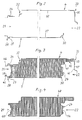
- zwei Teilschnitte durch ein unteres und ein oberes Stahlband entsprechend der Linie II - II in Fig. 1 in vergrößertem Maßstab, wobei das untere Stahlband an seinem der Federseite zugeordneten Rand vorprofiliert und an einer Biegekante geschwächt sowie an seinem der Nutseite zugeordneten Rand fertigprofiliert ist und wobei das obere Stahlband an seinen beiden Rändern vorprofiliert und jeweils an einer Biegekante geschwächt ist,
- Fig. 3
- zwei Teilschnitte durch das untere und das obere Stahlband, eine seitenprofilierte Füllstoff-Formplatte und zwei Klebstoffschichten entsprechend der Linie III - III in Fig. 1 in vergrößertem Maßstab in der Phase vor dem Fertigprofilieren des vorprofilierten Randes des unteren Stahlbandes und der beiden vorprofilierten Ränder des oberen Stahlbandes,
- Fig. 4
- zwei Teilschnitte durch das untere und das obere Stahlband, eine seitenprofilierte Füllstoff-Formplatte und zwei Klebstoffschichten entsprechend der Linie IV - IV in Fig. 1 in vergrößertem Maßstab in der Phase nach dem Fertigprofilieren des vorprofilierten Randes des unteren Stahlbandes und der beiden vorprofilierten Ränder des oberen Stahlbandes,
- Fig. 5
- zwei Teilschnitte durch das untere und das obere Stahlband, eine seitenprofilierte Füllstoff-Formplatte und zwei Klebstoffschichten mit einem Schnitt durch ein an die seitenprofilierte Füllstoff-Formplatte angeklebtes Dichtband entsprechend der Linie V - V in Fig. 1 in vergrößertem Maßstab,
- Fig. 6
- einen Schnitt durch eine Bauplatte entsprechend der Linie VI - VI in Fig. 1 in vergrößertem Maßstab,
- Fig. 7
- einen Teilschnitt durch zwei zusammengefügte Bauplatten nach Fig. 6 in vergrößertem Maßstab.
- Fig. 1
- a plant for the production of fire-resistant heat-insulating building boards with a tongue and a tongue side as an embodiment in view,
- Fig. 2
- two partial sections through a lower and an upper steel strip according to the line II - II in Fig. 1 on an enlarged scale, the lower steel strip pre-profiled and at its edge associated with the spring side a bending edge is weakened and is fully profiled on its edge assigned to the groove side and the upper steel strip is pre-profiled on both edges and is weakened on each bending edge,
- Fig. 3
- two partial sections through the lower and the upper steel strip, a side-profiled filler molding plate and two adhesive layers according to the line III - III in Fig. 1 on an enlarged scale in the phase before the pre-profiling of the pre-profiled edge of the lower steel strip and the two pre-profiled edges of the upper Steel strip,
- Fig. 4
- two partial sections through the lower and the upper steel strip, a side-profiled filler molding plate and two adhesive layers according to the line IV - IV in Fig. 1 on an enlarged scale in the phase after the profiling of the pre-profiled edge of the lower steel strip and the two pre-profiled edges of the upper Steel strip,
- Fig. 5
- two partial cuts through the lower and the upper steel strip, a side-profiled filler molding plate and two adhesive layers with a cut through a sealing tape adhered to the side-profiled filler molding plate according to the line V - V in FIG. 1 on an enlarged scale,
- Fig. 6
- 2 shows a section through a building board along the line VI-VI in FIG. 1 on an enlarged scale,
- Fig. 7
- a partial section through two assembled building boards according to FIG. 6 on an enlarged scale.
In einer Anlage 1 zur kontinuierlichen Herstellung von feuerbeständigen wärmeisolierenden Bauplatten 2 in Sandwichbauweise werden ein unteres (3) und ein oberes Stahlband 4 als Außenschichten mit gleicher Geschwindigkeit v in Bandlängsrichtung bewegt. Sowohl das untere (3) als auch das obere Stahlband 4 entsteht durch Verbinden von Einzelbändern 5, 6 jeweils an dem Bandende 7, 8 mit dem Bandanfang 9, 10.In a
Die Einzelbänder 5, 6 werden jeweils von einer Bandabhaspelstation 11, 12 zu einer Bandschopf- und -verbindungsstation 13, 14 geführt. Zwei Bandschlingen 15, 16 dienen der Speicherung des unteren (3) und des oberen Stahlbandes 4.The
Das untere (3) und das obere Stahlband 4 weisen je eine Bandbreite 17, 18 auf, die sich aus der Abwicklungslänge einer unteren (19) und einer oberen Außenschale 20 einer Bauplatte 2 ergibt (Fig. 6).The lower (3) and the
Jede Bauplatte 2, die eine Nut- (21) und eine Federseite 22 hat, ist ein fünfschichtiges Sandwichelement, wobei die untere Außenschale 19, eine Klebstoffschicht 23, eine seitenprofilierte Füllstoff-Formplatte 24 aus Mineralwolle, eine Klebstoffschicht 25 und die obere Außenschale 20 übereinanderliegen. An der Federseite 22 einer jeden Bauplatte 2 ist ein nicht brennbarer Dichtstreifen 26 angeklebt.Each
Der in Fig. 6 dargestellte Querschnitt einer Bauplatte 2 ist maßgebend für die Profilierung des unteren (3) und des oberen Stahlbandes 4.The cross section of a
In einer Bandprofilierstation 27 wird das untere Stahlband 3 an seinem der Nutseite 21 zugeordneten Rand 28 vorprofiliert und an einer Biegekante 29 geschwächt sowie an seinem der Federseite 22 zugeordneten Rand 30 fertigprofiliert (Fig. 2).In a
Gleichzeitig wird in einer Bandprofilierstation 31 das obere Stahlband 4 an seinen beiden Rändern 32, 33 vorprofiliert und jeweils an einer Biegekante 34, 35 geschwächt (Fig. 2).At the same time, the
Von der Bandprofilierstation 27 aus gelangt das untere Stahlband 3 in eine Klebstoff-Sprühstation 36, die auf die Innenfläche 37 des unteren Stahlbandes 3 eine Klebstoffschicht 38 aufsprüht.The
Anschließend werden auf das mit der Klebstoffschicht 38 versehene untere Stahlband 3 seitenprofilierte Füllstoff-Formplatten 24 stoßförmig hintereinander aufgelegt, und zwar mit Hilfe einer Beschickeinrichtung 39. Dabei wird der fertigprofilierte Rand 30 des unteren Stahlbandes 3 als Seitenanschlag benutzt.Subsequently,
Danach wird in einer Klebstoff-Sprühstation 40 die obere Mantelfläche 41 der Füllstoff-Formplatten 24 in dem Bereich der vorgesehenen Vereinigung mit der Innenfläche 42 des oberen Stahlbandes 4 eine Klebstoffschicht 43 aufgesprüht.Then, in an
Sodann wird in einer Bandprofilierstation 44 zunächst das an seinen beiden Rändern 32, 33 vorprofilierte obere Stahlband 4 auf die mit der Klebstoffschicht 43 versehenen Füllstoff-Formplatten 24 gedrückt (Fig. 3).Then, in a
In der Bandprofilierstation 44 werden ferner der vorprofilierte Rand 28 des unteren Stahlbandes 3 und die beiden vorprofilierten Ränder 32, 33 des oberen Stahlbandes 4 entsprechend der seitenprofilierten Füllstoff-Formplatten 24 fertigprofiliert (Fig. 4).In the
Das Fertigprofilieren der Ränder 28, 32, 33 ist hier durch rechtwinkliges Umbiegen der Randschenkel 45, 46, 47 an den Biegekanten 29, 34, 35 ausgeführt worden.The finished profiling of the
Aus der Bandprofilierstation 44 tritt ein Sandwichstrang 48 mit der Geschwindigkeit v heraus, der nacheinander eine Heizstation 49 und eine Aushärtestation 50 zum Aushärten der Klebstoffschichten 38, 43 durchläuft.A
Die Aushärtestation 50 besitzt einen Doppelbandantrieb 51 zur Erzeugung der Vorschubbewegung des Sandwichstranges 48 mit der Geschwindigkeit v.The
An den aus der Aushärtestation 50 austretenden Sandwichstrang 48 wird auf der Federseite 22 ein nicht brennbares Dichtband 52 mit Hilfe einer Anklebevorrichtung 53 in eine Nut 54 der Füllstoff-Formplatten 24 eingeklebt.On the
Eine Abtrenneinrichtung 55 trennt von dem mit dem Dichtband 52 verbundenen Sandwichstrang 48 einzelne Bauplatten 2 rechtwinklig zu der Nut- (21) und der Federseite 22 ab.A separating
Das Abtrennen einer Bauplatte 2 von dem Sandwichstrang 48 erfolgt stets an der Stoßstelle 56 zweier Füllstoff-Formplatten 24.A
Die Länge 57 einer Bauplatte 2 ist somit gleich der Länge 58 einer Füllstoff-Formplatte 24 abzüglich der beim Durchtrennen des Sandwichstranges 48 entstehenden Trennfugenbreite.The
Der Abtrenneinrichtung 55 ist eine Einrichtung 59 zum Abstapeln einzelner Bauplatten 2 nachgeordnet.The separating
Die Füllstoff-Formplatte 24 hat auf der Nutseite 21 eine Nut 60, die der teilweisen Aufnahme des Dichtstreifens 26 bei zwei zusammengefügten Bauplatten 2 dient (Fig. 7).The
Der Stoßbereich zweier Bauplatten 2 ist mit 61 bezeichnet (Fig. 7).The joint area of two
- 11
- Anlageinvestment
- 22nd
- BauplatteBuilding board
- 33rd
- unteres Stahlbandlower steel band
- 44th
- oberes Stahlbandupper steel band
- 55
- EinzelbandSingle volume
- 66
- ""
- 77
- BandendeBand end
- 88th
- ""
- 99
- BandanfangBand start
- 1010th
- ""
- 1111
- BandabhaspelstationReel reel station
- 1212th
- ""
- 1313
- Bandschopf- und -verbindungsstationRibbon crimping and joining station
- 1414
- Bandschopf- und -verbindungsstationRibbon crimping and joining station
- 1515
- BandschlingeSling
- 1616
- ""
- 1717th
- BandbreiteBandwidth
- 1818th
- ""
- 1919th
- untere Außenschalelower outer shell
- 2020th
- obere Außenschaleupper outer shell
- 2121
- NutseiteGroove side
- 2222
- FederseiteSpring side
- 2323
- KlebstoffschichtAdhesive layer
- 2424th
- Füllstoff-FormplatteFiller molding plate
- 2525th
- KlebstoffschichtAdhesive layer
- 2626
- DichtstreifenSealing strips
- 2727
- BandprofilierstationBelt profiling station
- 2828
- Randedge
- 2929
- BiegekanteBending edge
- 3030th
- Randedge
- 3131
- BandprofilierstationBelt profiling station
- 3232
- Randedge
- 3333
- ""
- 3434
- BiegekanteBending edge
- 3535
- ""
- 3636
- Klebstoff-SprühstationGlue spray station
- 3737
- InnenflächeInner surface
- 3838
- KlebstoffschichtAdhesive layer
- 3939
- BeschickeinrichtungLoading device
- 4040
- Klebstoff-SprühstationGlue spray station
- 4141
- MantelflächeLateral surface
- 4242
- InnenflächeInner surface
- 4343
- KlebstoffschichtAdhesive layer
- 4444
- BandprofilierstationBelt profiling station
- 4545
- RandschenkelMarginal thighs
- 4646
- ""
- 4747
- ""
- 4848
- SandwichstrangSandwich strand
- 4949
- HeizstationHeating station
- 5050
- AushärtestationCuring station
- 5151
- DoppelbandantriebDouble belt drive
- 5252
- DichtbandSealing tape
- 5353
- AnklebevorrichtungGluing device
- 5454
- NutGroove
- 5555
- AbtrenneinrichtungSeparation device
- 5656
- StoßstelleJoint
- 5757
- Längelength
- 5858
- ""
- 5959
- Einrichtung zum AbstapelnStacking device
- 6060
- NutGroove
- 6161
- StoßbereichJoint area
- vv
- Geschwindigkeitspeed
Claims (3)
Applications Claiming Priority (2)
| Application Number | Priority Date | Filing Date | Title |
|---|---|---|---|
| DE19619063A DE19619063A1 (en) | 1996-05-13 | 1996-05-13 | Process for the continuous production of fire-resistant, heat-insulating building boards in sandwich construction |
| DE19619063 | 1996-05-13 |
Publications (3)
| Publication Number | Publication Date |
|---|---|
| EP0807518A2 true EP0807518A2 (en) | 1997-11-19 |
| EP0807518A3 EP0807518A3 (en) | 1998-08-12 |
| EP0807518B1 EP0807518B1 (en) | 2003-04-09 |
Family
ID=7794060
Family Applications (1)
| Application Number | Title | Priority Date | Filing Date |
|---|---|---|---|
| EP97107489A Expired - Lifetime EP0807518B1 (en) | 1996-05-13 | 1997-05-07 | A method for the continuous manufacturing of fire-resistant sandwich panels |
Country Status (3)
| Country | Link |
|---|---|
| EP (1) | EP0807518B1 (en) |
| AT (1) | ATE236789T1 (en) |
| DE (2) | DE19619063A1 (en) |
Cited By (4)
| Publication number | Priority date | Publication date | Assignee | Title |
|---|---|---|---|---|
| ES2168946A1 (en) * | 2000-03-20 | 2002-06-16 | Saint Gobain Cristaleria S A | The perfected hidden union applicable to insulation panels and similar products |
| EP1331319A1 (en) * | 2002-01-29 | 2003-07-30 | Paroc Group Oy Ab | Method for making a sandwich element |
| FR2837743A1 (en) * | 2002-04-02 | 2003-10-03 | Paneles Embo Sl | Manufacturing panels covered on both sides by aluminum, supplies metal sheet from rolls, and presses it against hot adhesive coating on foam panels |
| WO2012052354A3 (en) * | 2010-10-22 | 2012-06-14 | Kraussmaffei Technologies Gmbh | Device and method for producing sandwich elements with an integrated seal |
Families Citing this family (1)
| Publication number | Priority date | Publication date | Assignee | Title |
|---|---|---|---|---|
| DE19938014A1 (en) * | 1999-08-11 | 2001-03-15 | Thyssenkrupp Stahl Ag | Building system for walls and roofs uses sandwich components with flat, or trapezoidal outer shell of metal, flat or profiled inner shell of metal and core of plastics, hard foam or mineral fibers |
Family Cites Families (7)
| Publication number | Priority date | Publication date | Assignee | Title |
|---|---|---|---|---|
| US2710081A (en) * | 1952-01-24 | 1955-06-07 | Martin Parry Corp | Wall panel structure |
| US3344503A (en) * | 1963-12-12 | 1967-10-03 | Hauserman Co E F | Apparatus and method for manufacture of building panels |
| DE1609668B2 (en) * | 1966-05-28 | 1973-01-04 | Hoesch Ag, 4600 Dortmund | Process for the continuous production of composite elements |
| AT312907B (en) * | 1968-07-17 | 1974-01-25 | Hoesch Ag | Process and device for the continuous production of multilayer wall elements and wall element produced by the process |
| DE2304886C3 (en) * | 1973-02-01 | 1975-11-27 | Hoesch Werke Ag, 4600 Dortmund | Process for the continuous production of a component |
| IE69262B1 (en) * | 1991-09-25 | 1996-08-21 | Modular Erectors Ltd | A method and apparatus for forming a laminated panel |
| WO1994015033A1 (en) * | 1992-12-28 | 1994-07-07 | Ig-Technical Research Inc. | Refractory heat-insulating panel |
-
1996
- 1996-05-13 DE DE19619063A patent/DE19619063A1/en not_active Withdrawn
-
1997
- 1997-05-07 EP EP97107489A patent/EP0807518B1/en not_active Expired - Lifetime
- 1997-05-07 AT AT97107489T patent/ATE236789T1/en not_active IP Right Cessation
- 1997-05-07 DE DE59709741T patent/DE59709741D1/en not_active Expired - Fee Related
Cited By (6)
| Publication number | Priority date | Publication date | Assignee | Title |
|---|---|---|---|---|
| ES2168946A1 (en) * | 2000-03-20 | 2002-06-16 | Saint Gobain Cristaleria S A | The perfected hidden union applicable to insulation panels and similar products |
| EP1331319A1 (en) * | 2002-01-29 | 2003-07-30 | Paroc Group Oy Ab | Method for making a sandwich element |
| FR2837743A1 (en) * | 2002-04-02 | 2003-10-03 | Paneles Embo Sl | Manufacturing panels covered on both sides by aluminum, supplies metal sheet from rolls, and presses it against hot adhesive coating on foam panels |
| ES2263302A1 (en) * | 2002-04-02 | 2006-12-01 | Paneles Embo, S.L. | Manufacturing panels covered on both sides by aluminum, supplies metal sheet from rolls, and presses it against hot adhesive coating on foam panels |
| ES2263302B1 (en) * | 2002-04-02 | 2008-06-16 | Paneles Embo, S.L. | CONTINUOUS MANUFACTURING PROCEDURE OF STRATIFIED PANELS AND PANEL SO OBTAINED. |
| WO2012052354A3 (en) * | 2010-10-22 | 2012-06-14 | Kraussmaffei Technologies Gmbh | Device and method for producing sandwich elements with an integrated seal |
Also Published As
| Publication number | Publication date |
|---|---|
| EP0807518B1 (en) | 2003-04-09 |
| ATE236789T1 (en) | 2003-04-15 |
| DE59709741D1 (en) | 2003-05-15 |
| DE19619063A1 (en) | 1997-11-20 |
| EP0807518A3 (en) | 1998-08-12 |
Similar Documents
| Publication | Publication Date | Title |
|---|---|---|
| DE4103426A1 (en) | FLAT, RECTANGULAR COMPOSITE INSULATION | |
| CH663456A5 (en) | FOAM INSULATING PIPE OR FOAM INSULATING PLATE MADE OF FLEXIBLE FOAM PLASTIC WITH A SLOT AND SPRING LOCKING SYSTEM ARRANGED IN LONG-AXIS. | |
| DE2747978C3 (en) | Method for producing an endless composite web | |
| DE102008022805A1 (en) | Wavy veneer board for use with lightweight board, in e.g. furniture construction, has laminar wood veneers stuck with each other, where veneer board exhibits waveform e.g. zigzag waveform, viewed in longitudinal section | |
| EP0727376B1 (en) | Device for dividing a running paper web | |
| EP0807518B1 (en) | A method for the continuous manufacturing of fire-resistant sandwich panels | |
| DE4404492A1 (en) | Multilayer composite tube for hot water, sanitary applications etc. | |
| EP1982607B1 (en) | Thermoplastic hair connecting element | |
| DE102008022806A1 (en) | Light-weight building board has waved timber inlay layer, where timber inlay layer of double-sided wave form rests over wave crest and wave trough at cover | |
| EP0339133B1 (en) | Rail wheel | |
| EP3464742B1 (en) | Seal strip for sealing gaps between construction elements and method for producing a seal strip | |
| EP0898629A1 (en) | Bundled prestress tendon and method for producing same | |
| DE19622316A1 (en) | Masonry structures | |
| WO2007033643A2 (en) | Roller brush and method for production thereof | |
| DE3221797A1 (en) | Method of joining metallic inner and outer parts of a composite profile | |
| DE19756621B4 (en) | Process for the continuous production of coated profiles for drawers or the like | |
| DE68921991T2 (en) | BAUPANEEL. | |
| AT208047B (en) | Reticulated cell arrangement and method of making the same | |
| EP0958995B1 (en) | Wall element for the body structure of a vehicle and fabrication process of such a wall element | |
| DE2244755C3 (en) | Two-layer material | |
| DE19732599B4 (en) | Method for juxtaposing lattice girders | |
| DE19904845C1 (en) | Production method for veneer strip involves measuring, sawing and bundling up lengths of veneer strip, inserting galvanized wires and joining end sides | |
| AT411244B (en) | METHOD AND DEVICE FOR THE PRODUCTION OF A GLASS WOOL MATERIAL | |
| AT509804B1 (en) | DUCT TAPE | |
| DE1415692B2 (en) | Ribbon cable |
Legal Events
| Date | Code | Title | Description |
|---|---|---|---|
| PUAI | Public reference made under article 153(3) epc to a published international application that has entered the european phase |
Free format text: ORIGINAL CODE: 0009012 |
|
| AK | Designated contracting states |
Kind code of ref document: A2 Designated state(s): AT BE CH DE FR LI NL |
|
| EL | Fr: translation of claims filed | ||
| TCNL | Nl: translation of patent claims filed | ||
| PUAL | Search report despatched |
Free format text: ORIGINAL CODE: 0009013 |
|
| AK | Designated contracting states |
Kind code of ref document: A3 Designated state(s): AT BE CH DE FR LI NL |
|
| 17P | Request for examination filed |
Effective date: 19980827 |
|
| RAP1 | Party data changed (applicant data changed or rights of an application transferred) |
Owner name: THYSSEN KRUPP STAHL AG |
|
| RAP1 | Party data changed (applicant data changed or rights of an application transferred) |
Owner name: THYSSENKRUPP STAHL AG |
|
| GRAH | Despatch of communication of intention to grant a patent |
Free format text: ORIGINAL CODE: EPIDOS IGRA |
|
| GRAH | Despatch of communication of intention to grant a patent |
Free format text: ORIGINAL CODE: EPIDOS IGRA |
|
| GRAA | (expected) grant |
Free format text: ORIGINAL CODE: 0009210 |
|
| GRAH | Despatch of communication of intention to grant a patent |
Free format text: ORIGINAL CODE: EPIDOS IGRA |
|
| AK | Designated contracting states |
Designated state(s): AT BE CH DE FR LI NL |
|
| REG | Reference to a national code |
Ref country code: CH Ref legal event code: EP |
|
| PGFP | Annual fee paid to national office [announced via postgrant information from national office to epo] |
Ref country code: FR Payment date: 20030425 Year of fee payment: 7 Ref country code: CH Payment date: 20030425 Year of fee payment: 7 |
|
| PGFP | Annual fee paid to national office [announced via postgrant information from national office to epo] |
Ref country code: NL Payment date: 20030428 Year of fee payment: 7 Ref country code: AT Payment date: 20030428 Year of fee payment: 7 |
|
| PGFP | Annual fee paid to national office [announced via postgrant information from national office to epo] |
Ref country code: BE Payment date: 20030514 Year of fee payment: 7 |
|
| ET | Fr: translation filed | ||
| PLBE | No opposition filed within time limit |
Free format text: ORIGINAL CODE: 0009261 |
|
| STAA | Information on the status of an ep patent application or granted ep patent |
Free format text: STATUS: NO OPPOSITION FILED WITHIN TIME LIMIT |
|
| 26N | No opposition filed |
Effective date: 20040112 |
|
| PG25 | Lapsed in a contracting state [announced via postgrant information from national office to epo] |
Ref country code: AT Free format text: LAPSE BECAUSE OF NON-PAYMENT OF DUE FEES Effective date: 20040507 |
|
| PG25 | Lapsed in a contracting state [announced via postgrant information from national office to epo] |
Ref country code: LI Free format text: LAPSE BECAUSE OF NON-PAYMENT OF DUE FEES Effective date: 20040531 Ref country code: CH Free format text: LAPSE BECAUSE OF NON-PAYMENT OF DUE FEES Effective date: 20040531 Ref country code: BE Free format text: LAPSE BECAUSE OF NON-PAYMENT OF DUE FEES Effective date: 20040531 |
|
| BERE | Be: lapsed |
Owner name: *THYSSENKRUPP STAHL A.G. Effective date: 20040531 |
|
| PG25 | Lapsed in a contracting state [announced via postgrant information from national office to epo] |
Ref country code: NL Free format text: LAPSE BECAUSE OF NON-PAYMENT OF DUE FEES Effective date: 20041201 |
|
| REG | Reference to a national code |
Ref country code: CH Ref legal event code: PL |
|
| PG25 | Lapsed in a contracting state [announced via postgrant information from national office to epo] |
Ref country code: FR Free format text: LAPSE BECAUSE OF NON-PAYMENT OF DUE FEES Effective date: 20050131 |
|
| NLV4 | Nl: lapsed or anulled due to non-payment of the annual fee |
Effective date: 20041201 |
|
| REG | Reference to a national code |
Ref country code: FR Ref legal event code: ST |
|
| PGFP | Annual fee paid to national office [announced via postgrant information from national office to epo] |
Ref country code: DE Payment date: 20060519 Year of fee payment: 10 |
|
| PG25 | Lapsed in a contracting state [announced via postgrant information from national office to epo] |
Ref country code: DE Free format text: LAPSE BECAUSE OF NON-PAYMENT OF DUE FEES Effective date: 20071201 |