EP0807499A2 - Agrafeuse électrique - Google Patents
Agrafeuse électrique Download PDFInfo
- Publication number
- EP0807499A2 EP0807499A2 EP97107728A EP97107728A EP0807499A2 EP 0807499 A2 EP0807499 A2 EP 0807499A2 EP 97107728 A EP97107728 A EP 97107728A EP 97107728 A EP97107728 A EP 97107728A EP 0807499 A2 EP0807499 A2 EP 0807499A2
- Authority
- EP
- European Patent Office
- Prior art keywords
- sheet stack
- actuator
- throat
- sub
- stapling
- Prior art date
- Legal status (The legal status is an assumption and is not a legal conclusion. Google has not performed a legal analysis and makes no representation as to the accuracy of the status listed.)
- Granted
Links
Images


Classifications
-
- B—PERFORMING OPERATIONS; TRANSPORTING
- B27—WORKING OR PRESERVING WOOD OR SIMILAR MATERIAL; NAILING OR STAPLING MACHINES IN GENERAL
- B27F—DOVETAILED WORK; TENONS; SLOTTING MACHINES FOR WOOD OR SIMILAR MATERIAL; NAILING OR STAPLING MACHINES
- B27F7/00—Nailing or stapling; Nailed or stapled work
- B27F7/02—Nailing machines
- B27F7/025—Nailing machines for inserting joint-nails
Definitions
- This invention relates to an electric stapler for stapling a sheet stack, and more particularly to an electric stapler which can staple a sheet stack so that the staple is positioned in a corner of the sheet at an angle to adjacent edges of the sheet stack (will be referred to as “slantwise stapling” hereinbelow) as well as so that the staple is positioned in parallel to an edge of the sheet stack (will be referred to as “parallel stapling” hereinbelow).
- the actuator is generally provided with a pair of switching members which are arranged in the direction of width of a sheet stack at a predetermined distance and are pushed inward by an edge of a sheet stack when the sheet stack is inserted into throat.
- the switching members actuate the stapling mechanism when they are moved to a predetermined position, whereby a predetermined position of the sheet stack is stapled in parallel stapling.
- the switching members are still short of said predetermined position where they actuate the stapling mechanism and accordingly the stapling mechanism cannot be actuated.
- the stapling mechanism can be actuated if the sheet stack is further inserted into the throat. However this results in slantwise stapling in a portion remote from the predetermined position of the sheet stack in the corner.
- a manual switch or the like for actuating the stapling mechanism is separately provided and the manual switch is operated to actuate the stapling mechanism when a corner of a sheet stack is inserted into the throat by a certain amount, the stapled position of the sheet stack will vary from sheet stack to sheet stack though the sheet stacks can be stapled in slantwise stapling.
- a slantwise stapling adapter is employed when effecting slantwise stapling in such a stapler.
- the adapter must be removed from the stapler when parallel stapling is to be effected, which can result in the loss of the adapter.
- the primary object of the present invention is to provide an electric stapler which can be easily switched from parallel stapling to slantwise stapling and from the latter to the former.
- an electric stapler comprising a stapling mechanism which is connected to a power source through a switch and staples a sheet stack inserted into a throat and an actuator which is adapted to abut against an edge of a sheet stack at a plurality of positions along the edge of the sheet stack and to be moved by the sheet stack in response to insertion thereof to an operative position where it operates the switch to actuate the stapling mechanism, wherein the improvement comprises
- the sub-actuator be urged forward by a spring member and be moved to drive the actuator to said operative position overcoming the force of the spring member.
- the electric stapler of the present invention can be easily switched from parallel stapling to slantwise stapling and from the latter to the former by only erecting or flattening the sub-actuator. Further since the sub-actuator need not be removed from the stapler, there is no fear of loss of the sub-actuator unlike the conventional adapter.
- control system may be simple in structure.
- the stapler of this embodiment is mounted, for instance, on the outer wall of a sheet sorter which is provided with a plurality of bins each of which receives a plurality of sheets discharged from an image recording apparatus such as a printer, a copier or the like and forms thereon a stack of sheets.
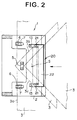
- the stapler 1 has a throat 4 into which a sheet stack 3 to be stapled is inserted.
- the throat 4 opens in the front face of a body frame 2 and extends from one side face of the body frame 2 to the other.
- the lower side of the throat 4 is defined by a flat surface 4a and the sheet stack 3 is rested on the surface 4a.
- the surface 4a will be referred to as the "sheet rest surface 4a", hereinbelow.
- a pair of slots 6 are formed on opposite sides of the stapling portion 5 to extend in the direction of insertion of the sheet stack 3 (from right to left in Figures 2 and 4).
- a pair of levers 7 project upward beyond the sheet rest surface 4a from the respective slots
- the levers 7 are supported for rotation on a shaft 8 which extends normal to the direction of insertion of the sheet stack 3, and the lower end portions of the respective levers 7 are connected by a connecting member 9 extending in parallel to the shaft 8.
- the levers 7 are urged in the clockwise direction as seen in Figure 4 so that the upper ends thereof are directed forward by a coiled spring 10 connected to the connecting member 9 at its one end and to an engagement piece 2a on the body frame 2.
- the levers 7 are held in the position shown by the solid line in Figure 4 with their side edges in abutment against the forward edges of the respective slots 6.
- a switch 11 for energizing the stapling mechanism is mounted on a mount 2b in the body frame 2.
- the levers 7 When the levers 7 are rotated in the counterclockwise direction in Figure 4 to a predetermined position, one of the levers 7 or the connecting member 9 acts on the switch 11 and the switch 11 is turned on to energize the stapling mechanism. That is, the levers 7 function as an actuator for actuating the stapling mechanism.
- a sub-actuator 20 for slantwise stapling is provided near the entrance to the throat 4 to be movable between an erected position shown in Figures 1, 2 and 4 and a horizontal position shown in Figure 3.
- the sub-actuator 20 comprises a pair of levers 21 respectively extending through a pair of slots 13 which are formed in front of the actuator levers 7 to extend in the direction of insertion of the sheet stack 3 and are spaced from each other in a direction normal to the direction of insertion of the sheet stack 3, and a connecting bar 22 which is in the form of an elongated flat plate and connects the upper end portions of the respective levers 21.
- the connecting bar 22 is inclined downward at a predetermined angle toward the back of the throat 4 as shown in Figure 4.
- a pair of sliding members 23 are disposed below the slots 13 to be slidable left and right in Figure 4 on a horizontal guide plate 12 provided in the body frame 2.
- the sliding members 23 are urged rightward as seen in Figure 4 by a linear spring member 25 fixed to the body frame 2 by a screw 14 at the middle thereof as shown in Figure 3.
- the lower ends of the levers 21 of the sub-actuator 20 are mounted on the front end portions of the respective sliding members 23 to be rotatable through about 90° about pivot pins 24 normal to the direction of insertion of the sheet stack 3.
- the sub-actuator 20 is selectively held in the erected position shown by the solid line in Figure 4 where the levers 21 are erected or the horizontal position shown by the chained line in Figure 4 where the levers 21 are flattened by a suitable click stop mechanism.
- levers 21 are erected or flattened
- the sub-actuator 20 is normally held in the position shown by the solid line in Figure 4 by the spring member 25 which urges rightward the sliding members 23.
- the sub-actuator 20 is rotated through about 90° between the erected position and the horizontal position with the connecting bar 22 held by the operator's fingers.
- a recess 15 is formed on the front face of the body frame 2 to extend along the lower edge of the connecting bar 22.
- the sub-actuator 20 When slantwise stapling is to be effected, the sub-actuator 20 is erected. When a corner of a sheet stack 3 is inserted into the throat 4 with the sub-actuator 20 erected, the levers 21 are brought into abut against the edges 3b and 3c ( Figure 2) of the sheet stack 3 forming the corner, and as the sheet stack 3 is further inserted into the throat 4, the levers 21 are pushed leftward by the sheet stack 3 along the slots 13 overcoming the force of the spring member 25 while guiding the sheet stack 3.
- the electric stapler 1 of this embodiment can be easily switched from parallel stapling to slantwise stapling and from the latter to the former by only rotating the sub-actuator 20. Further since the sub-actuator 20 need not be removed from the stapler 1, there is no fear of loss of the sub-actuator 20 unlike the conventional adapter.
- one of the levers 7 or the connecting member 9 acts on the switch 11 to actuate the stapling mechanism
- a photoelectric sensor or the like which detects the position of the levers 7 may be employed to actuate the stapling mechanism.
Landscapes
- Engineering & Computer Science (AREA)
- Mechanical Engineering (AREA)
- Life Sciences & Earth Sciences (AREA)
- Forests & Forestry (AREA)
- Portable Nailing Machines And Staplers (AREA)
- Dovetailed Work, And Nailing Machines And Stapling Machines For Wood (AREA)
Applications Claiming Priority (3)
| Application Number | Priority Date | Filing Date | Title |
|---|---|---|---|
| JP11751596 | 1996-05-13 | ||
| JP11751596A JP3554632B2 (ja) | 1996-05-13 | 1996-05-13 | 電動ステープラ |
| JP117515/96 | 1996-05-13 |
Publications (3)
| Publication Number | Publication Date |
|---|---|
| EP0807499A2 true EP0807499A2 (fr) | 1997-11-19 |
| EP0807499A3 EP0807499A3 (fr) | 1998-11-18 |
| EP0807499B1 EP0807499B1 (fr) | 2002-11-13 |
Family
ID=14713680
Family Applications (1)
| Application Number | Title | Priority Date | Filing Date |
|---|---|---|---|
| EP97107728A Expired - Lifetime EP0807499B1 (fr) | 1996-05-13 | 1997-05-12 | Agrafeuse électrique |
Country Status (4)
| Country | Link |
|---|---|
| US (1) | US5803337A (fr) |
| EP (1) | EP0807499B1 (fr) |
| JP (1) | JP3554632B2 (fr) |
| DE (1) | DE69716995T2 (fr) |
Cited By (1)
| Publication number | Priority date | Publication date | Assignee | Title |
|---|---|---|---|---|
| EP0846533A3 (fr) * | 1996-11-14 | 1998-11-25 | Riso Kagaku Corporation | Agrafeuse électrique |
Families Citing this family (14)
| Publication number | Priority date | Publication date | Assignee | Title |
|---|---|---|---|---|
| US6341772B1 (en) * | 1997-01-10 | 2002-01-29 | Canon Kabushiki Kaisha | In line rotatable stapling device |
| US6199852B1 (en) * | 1998-09-03 | 2001-03-13 | Xerox Corporation | Device for positioning a sheet stack for stapling |
| US6173949B1 (en) * | 1998-09-03 | 2001-01-16 | Xerox Corporation | Device for positioning a sheet stack for stapling |
| US6135337A (en) * | 1999-01-15 | 2000-10-24 | Hunt Holdings, Inc. | Electric stapler |
| JP4296679B2 (ja) * | 2000-03-24 | 2009-07-15 | マックス株式会社 | 電動ステープラー |
| US6547119B2 (en) * | 2001-04-30 | 2003-04-15 | Chien Kai Huang | Power stapler |
| US7090110B2 (en) * | 2003-07-23 | 2006-08-15 | Acco Brands Usa Llc | Paper locator for a stapler |
| US20050023321A1 (en) * | 2003-07-31 | 2005-02-03 | Eric Tsai | Double trigger electric stapler |
| CN100509299C (zh) * | 2004-04-20 | 2009-07-08 | 阿科布兰兹美国有限责任公司 | 带有纸张导向器的订书机 |
| US20060016848A1 (en) * | 2004-07-26 | 2006-01-26 | Iraj Basti | Apparatus for evenly stapling stacks of paper at a desired angle |
| US7311236B2 (en) * | 2005-04-25 | 2007-12-25 | Tsi Manufacturing Llc | Electric stapler having two anvil plates and workpiece sensing controller |
| SE0500911L (sv) * | 2005-04-25 | 2006-02-21 | Isaberg Rapid Ab | Häftapparat |
| EP1955822B1 (fr) * | 2005-11-28 | 2012-06-13 | Max Co., Ltd. | Agrafeuse |
| US20110033218A1 (en) * | 2009-08-04 | 2011-02-10 | Kabushiki Kaisha Toshiba | Stapling apparatus, finishing apparatus, and stapling method |
Family Cites Families (8)
| Publication number | Priority date | Publication date | Assignee | Title |
|---|---|---|---|---|
| US4491260A (en) * | 1980-05-27 | 1985-01-01 | Jimena Carlos L | Electric stapler |
| IT1184850B (it) * | 1985-01-25 | 1987-10-28 | Balma Capoduri & C Spa | Elemento di azionamento per dispositivi elettromeccanici di automatizzazione di cucitrici da tavolo a punti metallici |
| NL8501337A (nl) * | 1985-05-10 | 1986-12-01 | Oce Nederland B V Patents And | Kopieerapparaat voorzien van een vellenhechtinrichting. |
| GB2260289B (en) * | 1991-09-10 | 1994-10-19 | Ofrex Group Holdings Plc | Improvements in or relating to an electrically-powered stapling machine |
| JPH05155510A (ja) * | 1991-11-29 | 1993-06-22 | Ricoh Co Ltd | シート材分配収納装置 |
| JPH07290373A (ja) * | 1994-04-21 | 1995-11-07 | Matsushita Electric Ind Co Ltd | 電動ステープラ |
| US5427296A (en) * | 1994-10-21 | 1995-06-27 | Chen; Bruce | Power stapler |
| US5595336A (en) * | 1995-11-01 | 1997-01-21 | Xerox Corporation | Safety stapler |
-
1996
- 1996-05-13 JP JP11751596A patent/JP3554632B2/ja not_active Expired - Lifetime
-
1997
- 1997-05-12 EP EP97107728A patent/EP0807499B1/fr not_active Expired - Lifetime
- 1997-05-12 DE DE69716995T patent/DE69716995T2/de not_active Expired - Fee Related
- 1997-05-13 US US08/855,390 patent/US5803337A/en not_active Expired - Lifetime
Cited By (1)
| Publication number | Priority date | Publication date | Assignee | Title |
|---|---|---|---|---|
| EP0846533A3 (fr) * | 1996-11-14 | 1998-11-25 | Riso Kagaku Corporation | Agrafeuse électrique |
Also Published As
| Publication number | Publication date |
|---|---|
| EP0807499A3 (fr) | 1998-11-18 |
| JPH09300307A (ja) | 1997-11-25 |
| DE69716995D1 (de) | 2002-12-19 |
| DE69716995T2 (de) | 2003-03-20 |
| EP0807499B1 (fr) | 2002-11-13 |
| JP3554632B2 (ja) | 2004-08-18 |
| US5803337A (en) | 1998-09-08 |
Similar Documents
| Publication | Publication Date | Title |
|---|---|---|
| EP0807499B1 (fr) | Agrafeuse électrique | |
| KR100401781B1 (ko) | 시트 처리 방법과 시트 처리 장치 및 이 장치를 구비한화상 형성 장치 | |
| EP0846533B1 (fr) | Agrafeuse électrique | |
| EP1160063B1 (fr) | Agrafeuse motorisée | |
| US20030044209A1 (en) | Sheet processing apparatus and image forming apparatus provided with the same | |
| US5188351A (en) | Multi-size paper cassette having a sheet size indicator | |
| JPS61261096A (ja) | 用紙ステープラ装置を備えた複写機 | |
| US6311971B1 (en) | Stacker controlling curl | |
| US6173949B1 (en) | Device for positioning a sheet stack for stapling | |
| JP4828477B2 (ja) | 用紙処理装置及び画像形成装置 | |
| USH1842H (en) | Pass through repositionable stapler-compiler system with clincher alignment system | |
| JP2003320502A (ja) | シート後処理装置及び画像形成装置 | |
| US6199852B1 (en) | Device for positioning a sheet stack for stapling | |
| JPS63109448A (ja) | 製本装置 | |
| SE517108C2 (sv) | Häftapparat | |
| US5375826A (en) | Paper tray control of a sheet feeder having biased nip rollers cooperative with the positioning of a paper tray | |
| US7121541B2 (en) | Stapling apparatus, sheet finishing apparatus, and image forming apparatus equipped with the sheet finishing apparatuses | |
| US5181643A (en) | Sheet-stapling device | |
| JPS63109449A (ja) | フイルタ装置 | |
| JP4024373B2 (ja) | シート後処理装置 | |
| JP3919561B2 (ja) | シート処理装置及びこれを備えた画像形成装置 | |
| CN113427917A (zh) | 打印装置以及排纸控制模块 | |
| JP3086664B2 (ja) | シート収納装置 | |
| JP3223588B2 (ja) | シート分配収容装置 | |
| JPH0333709Y2 (fr) |
Legal Events
| Date | Code | Title | Description |
|---|---|---|---|
| PUAI | Public reference made under article 153(3) epc to a published international application that has entered the european phase |
Free format text: ORIGINAL CODE: 0009012 |
|
| AK | Designated contracting states |
Kind code of ref document: A2 Designated state(s): DE FR GB |
|
| 17P | Request for examination filed |
Effective date: 19980714 |
|
| PUAL | Search report despatched |
Free format text: ORIGINAL CODE: 0009013 |
|
| AK | Designated contracting states |
Kind code of ref document: A3 Designated state(s): DE FR GB |
|
| GRAG | Despatch of communication of intention to grant |
Free format text: ORIGINAL CODE: EPIDOS AGRA |
|
| 17Q | First examination report despatched |
Effective date: 20020219 |
|
| GRAG | Despatch of communication of intention to grant |
Free format text: ORIGINAL CODE: EPIDOS AGRA |
|
| GRAH | Despatch of communication of intention to grant a patent |
Free format text: ORIGINAL CODE: EPIDOS IGRA |
|
| GRAH | Despatch of communication of intention to grant a patent |
Free format text: ORIGINAL CODE: EPIDOS IGRA |
|
| GRAA | (expected) grant |
Free format text: ORIGINAL CODE: 0009210 |
|
| AK | Designated contracting states |
Kind code of ref document: B1 Designated state(s): DE FR GB |
|
| REG | Reference to a national code |
Ref country code: GB Ref legal event code: FG4D |
|
| REF | Corresponds to: |
Ref document number: 69716995 Country of ref document: DE Date of ref document: 20021219 |
|
| ET | Fr: translation filed | ||
| PLBE | No opposition filed within time limit |
Free format text: ORIGINAL CODE: 0009261 |
|
| STAA | Information on the status of an ep patent application or granted ep patent |
Free format text: STATUS: NO OPPOSITION FILED WITHIN TIME LIMIT |
|
| 26N | No opposition filed |
Effective date: 20030814 |
|
| GBPC | Gb: european patent ceased through non-payment of renewal fee |
Effective date: 20030512 |
|
| REG | Reference to a national code |
Ref country code: GB Ref legal event code: 728V |
|
| REG | Reference to a national code |
Ref country code: GB Ref legal event code: 728Y |
|
| PGFP | Annual fee paid to national office [announced via postgrant information from national office to epo] |
Ref country code: DE Payment date: 20080515 Year of fee payment: 12 |
|
| PGFP | Annual fee paid to national office [announced via postgrant information from national office to epo] |
Ref country code: GB Payment date: 20080514 Year of fee payment: 12 |
|
| GBPC | Gb: european patent ceased through non-payment of renewal fee |
Effective date: 20090512 |
|
| REG | Reference to a national code |
Ref country code: FR Ref legal event code: ST Effective date: 20100129 |
|
| PG25 | Lapsed in a contracting state [announced via postgrant information from national office to epo] |
Ref country code: FR Free format text: LAPSE BECAUSE OF NON-PAYMENT OF DUE FEES Effective date: 20090602 |
|
| PGFP | Annual fee paid to national office [announced via postgrant information from national office to epo] |
Ref country code: FR Payment date: 20080514 Year of fee payment: 12 |
|
| PG25 | Lapsed in a contracting state [announced via postgrant information from national office to epo] |
Ref country code: GB Free format text: LAPSE BECAUSE OF NON-PAYMENT OF DUE FEES Effective date: 20090512 |
|
| PG25 | Lapsed in a contracting state [announced via postgrant information from national office to epo] |
Ref country code: DE Free format text: LAPSE BECAUSE OF NON-PAYMENT OF DUE FEES Effective date: 20091201 |