EP0807461A2 - Horizontal drum reactor for the treatment of pasty or granular material - Google Patents
Horizontal drum reactor for the treatment of pasty or granular material Download PDFInfo
- Publication number
- EP0807461A2 EP0807461A2 EP97107615A EP97107615A EP0807461A2 EP 0807461 A2 EP0807461 A2 EP 0807461A2 EP 97107615 A EP97107615 A EP 97107615A EP 97107615 A EP97107615 A EP 97107615A EP 0807461 A2 EP0807461 A2 EP 0807461A2
- Authority
- EP
- European Patent Office
- Prior art keywords
- reactor
- hollow shaft
- space
- conveying
- reactor space
- Prior art date
- Legal status (The legal status is an assumption and is not a legal conclusion. Google has not performed a legal analysis and makes no representation as to the accuracy of the status listed.)
- Granted
Links
Images
Classifications
-
- B—PERFORMING OPERATIONS; TRANSPORTING
- B01—PHYSICAL OR CHEMICAL PROCESSES OR APPARATUS IN GENERAL
- B01J—CHEMICAL OR PHYSICAL PROCESSES, e.g. CATALYSIS OR COLLOID CHEMISTRY; THEIR RELEVANT APPARATUS
- B01J19/00—Chemical, physical or physico-chemical processes in general; Their relevant apparatus
- B01J19/18—Stationary reactors having moving elements inside
-
- B—PERFORMING OPERATIONS; TRANSPORTING
- B01—PHYSICAL OR CHEMICAL PROCESSES OR APPARATUS IN GENERAL
- B01J—CHEMICAL OR PHYSICAL PROCESSES, e.g. CATALYSIS OR COLLOID CHEMISTRY; THEIR RELEVANT APPARATUS
- B01J19/00—Chemical, physical or physico-chemical processes in general; Their relevant apparatus
- B01J19/18—Stationary reactors having moving elements inside
- B01J19/20—Stationary reactors having moving elements inside in the form of helices, e.g. screw reactors
-
- B—PERFORMING OPERATIONS; TRANSPORTING
- B01—PHYSICAL OR CHEMICAL PROCESSES OR APPARATUS IN GENERAL
- B01J—CHEMICAL OR PHYSICAL PROCESSES, e.g. CATALYSIS OR COLLOID CHEMISTRY; THEIR RELEVANT APPARATUS
- B01J2208/00—Processes carried out in the presence of solid particles; Reactors therefor
- B01J2208/00008—Controlling the process
- B01J2208/00017—Controlling the temperature
- B01J2208/00106—Controlling the temperature by indirect heat exchange
- B01J2208/00168—Controlling the temperature by indirect heat exchange with heat exchange elements outside the bed of solid particles
- B01J2208/00212—Plates; Jackets; Cylinders
-
- B—PERFORMING OPERATIONS; TRANSPORTING
- B01—PHYSICAL OR CHEMICAL PROCESSES OR APPARATUS IN GENERAL
- B01J—CHEMICAL OR PHYSICAL PROCESSES, e.g. CATALYSIS OR COLLOID CHEMISTRY; THEIR RELEVANT APPARATUS
- B01J2208/00—Processes carried out in the presence of solid particles; Reactors therefor
- B01J2208/00008—Controlling the process
- B01J2208/00017—Controlling the temperature
- B01J2208/00513—Controlling the temperature using inert heat absorbing solids in the bed
-
- B—PERFORMING OPERATIONS; TRANSPORTING
- B01—PHYSICAL OR CHEMICAL PROCESSES OR APPARATUS IN GENERAL
- B01J—CHEMICAL OR PHYSICAL PROCESSES, e.g. CATALYSIS OR COLLOID CHEMISTRY; THEIR RELEVANT APPARATUS
- B01J2219/00—Chemical, physical or physico-chemical processes in general; Their relevant apparatus
- B01J2219/18—Details relating to the spatial orientation of the reactor
- B01J2219/182—Details relating to the spatial orientation of the reactor horizontal
Definitions
- the invention relates to a non-rotating horizontal tube reactor for the mechanical and / or thermal treatment of pasty material or bulk material according to the preamble of claim 1.
- Pre-dried industrial or sewage sludge, waste or the like is known as horizontal tube reactors.
- rotary tube reactors and non-rotating reactors are equipped on the inside with moving conveying and / or shifting devices.
- problems frequently arise due to caking and incrustations, which prevent the mechanical conveying and shifting of the material to be treated, but in particular the introduction of heat into the material, via heating surfaces. Closed reactors heated from the outside via contact surfaces are limited in terms of material throughput and treatment temperature by the ratio of heating surface to reactor content or reactor throughput.
- non-rotating horizontal tube reactors with moving transfer and conveying devices are preferred for a wide variety of reasons.
- Comparatively narrow distributions of the residence times can be achieved with non-rotating tubular reactors compared to rotary tubular reactors, which can be improved even further by the formation of chambers in the reactor space by weirs.
- a short-circuit current through the reactor can be avoided in this way, in particular in the case of materials which liquefy at least briefly in the course of the treatment or which have a flowable behavior due to their consistency.
- the invention has for its object to provide a possibility in a non-rotating horizontal tube reactor of the type mentioned at the beginning to improve the material throughput limited by the ratio of the heating surface to the reactor contents.
- the invention has the advantage in the treatment of pasty materials and those that tend to stick and bake at temperatures below or in the range of the treatment temperature, that the movement of the balls in the reactor chamber means permanent cleaning of the inner wall of the reactor and the conveying and shifting elements takes place, whereby caking and clogging in the reactor are avoided.
- the movement of the balls opens up coarse grains and agglomerations of the material to be treated; the material is ground. This alone increases the reaction speeds and sales rates significantly.
- the essential advantage of the invention is evident in those thermal treatments in which the material to be treated has to be heated to the reaction temperature after being introduced into the reactor space.
- the material throughput through the reactor is due to the limited heat transfer area, which is usually the Corresponds to the outer surface of the reactor, limited.
- the balls are returned inside the hollow shaft passing through the reactor chamber, that is to say in the region of the reactor chamber itself at a temperature corresponding to the reaction temperature, so that no or at least no significant heat losses occur.
- the material throughput can be increased with the same reactor size.
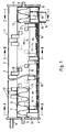
- FIG. 1 shows a schematic longitudinal section through a horizontal tube reactor 1 with a fixed jacket tube 2.
- the reactor space 3 formed within the casing tube 2 is bounded by a front end wall 4 and a rear end wall 5.
- a shaft 6 is rotatably supported in the end walls 4 and 5 and is designed as a hollow shaft 7 within the reactor space 3, that is to say between the end walls 4 and 5.
- the casing tube 2 is - as not specifically shown - heated from the outside in a manner known per se; for this purpose, the jacket can be designed as a double jacket in which a heat transfer medium circulates.
- the heat entered there is released through the jacket 2 to the material to be treated located in the reactor chamber 3, which is introduced through a material inlet 8 provided at the front end of the reactor 1 and is discharged after passing through the reactor chamber 3 through a material outlet 9 adjacent to the rear end wall 4 becomes.
- the hollow shaft 7 is designed as a conveying and shifting device and is equipped with paddles 10 for this purpose; instead of such paddles, a screw conveyor could also be provided.
- the material to be treated is conveyed by the paddles 10 in the direction of the arrows 11.
- a conveying screw 13 is arranged inside the casing 12 of the hollow shaft 7, the conveying direction (arrow 14) of which is opposite to that of the conveying of the material (arrows 11) in the reactor space.
- the screw conveyor 13 is firmly connected to the casing 12 of the hollow shaft 7 and thus rotates in the same direction and at the same speed as the hollow shaft 7.
- the reactor 1 is filled with spherical packing elements 15 up to a certain filling level.
- the fill level depends on the use of the reactor and the type of material to be treated. Also depending on the purpose of the Reactor, the filler 15 can consist of different materials, such as steel, other metals, ceramics or the like; the diameter of the balls can be 20 to 25 mm.
- the balls 15 are conveyed with the material to be treated in the conveying direction (arrow 11) through the reactor chamber 3.
- the material discharge 9 is through a sieve device 16, e.g. in the form of a perforated or slotted plate, through which the treated material can fall, but the balls 15 are retained.
- the discharge of the material is further promoted by the movement of the balls 15 on the screening device 16.
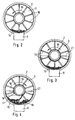
- the transducer 17 consists of a segment-shaped, blade-like receiving device which, like the paddle 10, is fastened to the casing 12 of the hollow shaft 7 and moves with its radially outer end along the inner wall of the casing tube 2.
- the jacket 12 of the hollow shaft has an opening 18.
- the reactor chamber 3 can be divided into individual chambers in the axial direction by weir-like walls; in particular, such a weir 21 should be arranged in front of the material discharge 9, which serves to even out the discharge of both the material and the balls.
Landscapes
- Chemical & Material Sciences (AREA)
- Organic Chemistry (AREA)
- Chemical Kinetics & Catalysis (AREA)
- Physical Or Chemical Processes And Apparatus (AREA)
- Treatment Of Sludge (AREA)
- Processing Of Solid Wastes (AREA)
- Muffle Furnaces And Rotary Kilns (AREA)
- Crushing And Grinding (AREA)
- Disintegrating Or Milling (AREA)
- Drying Of Solid Materials (AREA)
- Apparatuses For Bulk Treatment Of Fruits And Vegetables And Apparatuses For Preparing Feeds (AREA)
- Devices And Processes Conducted In The Presence Of Fluids And Solid Particles (AREA)
- Control And Other Processes For Unpacking Of Materials (AREA)
Abstract
Bei einem nichtdrehenden liegenden Rohrreaktor (1) zur mechanischen und/oder thermischen Behandlung von pastösem Gut oder Schüttgut werden in den Reaktorraum (3) kugelförmige Mahl- und/oder Abreinigungskörper (15) eingegeben, die den Reaktorraum (3) mit dem zu behandelnden Material durchlaufen. Die Körper (15) werden am Austragsende des Reaktorraumes von dem behandelten Material getrennt, innerhalb der als Hohlwelle (7) ausgebildeten Welle (6) der Förder- und Umschichtelemente (10) zum Eintragsende des Reaktorraumes (3) zurückgeführt und dort wieder in den Reaktorraum (3) eingefördert. Die Körper (15) wirken so als Wärmeträger, durch die Wärme von Reaktorteilen geringeren Wärmebedarfs zu Stellen hohen Wärmebedarfs transportiert wird. Durch die Rückförderung der mit dem behandelten Gut aufgeheizten Körper (15) vom heißen Reaktorende zum vorderen Reaktorbereich innerhalb der Hohlwelle (7), also im Bereich des Reaktorraumes (3) selbst, entstehen keine oder jedenfalls keine nennenswerten Wärmeverluste, so daß bei gleicher Reaktorbaugröße der Materialdurchsatz gesteigert werden kann.
Description
Die Erfindung betrifft einen nichtdrehenden liegenden Rohrreaktor zur mechanischen und/oder thermischen Behandlung von pastösem Gut oder Schüttgut gemäß dem Oberbegriff des Patentanspruchs 1.The invention relates to a non-rotating horizontal tube reactor for the mechanical and / or thermal treatment of pasty material or bulk material according to the preamble of claim 1.
Für die mechanische und/oder thermische Behandlung von pastösem Gut oder Schüttgut, wie z.B. vorgetrockneten Industrie- oder Klärschlämmen, Abfällen oder dergleichen kennt man liegende Rohrreaktoren. Dabei unterscheidet man zwischen Drehrohrreaktoren und nichtdrehenden Reaktoren; letztere sind innen mit bewegten Förder- und/oder Umschichteinrichtungen ausgestattet. Bei der Behandlung solcher Materialien kommt es häufig zu Problemen durch Anbackungen und Verkrustungen, durch welche die mechanische Förderung und Umschichtung des zu behandelnden Gutes, insbesondere aber die Eintragung von Wärme in das Gut, über Heizflächen verhindert werden. Geschlossene, von außen über Kontaktflächen beheizte Reaktoren werden aber hinsichtlich des Materialdurchsatzes und der Behandlungstemperatur durch das Verhältnis von Heizfläche zu Reaktorinhalt bzw. Reaktordurchsatz begrenzt.For the mechanical and / or thermal treatment of pasty or bulk goods, e.g. Pre-dried industrial or sewage sludge, waste or the like is known as horizontal tube reactors. A distinction is made between rotary tube reactors and non-rotating reactors; the latter are equipped on the inside with moving conveying and / or shifting devices. In the treatment of such materials, problems frequently arise due to caking and incrustations, which prevent the mechanical conveying and shifting of the material to be treated, but in particular the introduction of heat into the material, via heating surfaces. Closed reactors heated from the outside via contact surfaces are limited in terms of material throughput and treatment temperature by the ratio of heating surface to reactor content or reactor throughput.
Für eine Vielzahl von Behandlungsverfahren sind aus den unterschiedlichsten Gründen nichtdrehende liegende Rohrreaktoren mit bewegten Umschicht- und Fördereinrichtungen zu bevorzugen. So können mit nichtdrehenden Rohrreaktoren gegenüber Drehrohrreaktoren vergleichsweise enge Verteilungen der Verweilzeiten erzielt werden, die durch Bildung von Kammern im Reaktorraum durch überfallwehre noch verbessert werden können. Insbesondere bei Materialien, die sich im Verlauf der Behandlung zumindest kurzzeitig verflüssigen oder durch ihre Konsistenz ein fließfähiges Verhalten zeigen, kann auf diese Weise ein Kurzschlußstrom durch den Reaktor vermieden werden.For a variety of treatment processes, non-rotating horizontal tube reactors with moving transfer and conveying devices are preferred for a wide variety of reasons. Comparatively narrow distributions of the residence times can be achieved with non-rotating tubular reactors compared to rotary tubular reactors, which can be improved even further by the formation of chambers in the reactor space by weirs. A short-circuit current through the reactor can be avoided in this way, in particular in the case of materials which liquefy at least briefly in the course of the treatment or which have a flowable behavior due to their consistency.
Schließlich erfordert die Beheizung des Rohrmantels bei feststehenden Reaktoren gegenüber solchen mit drehenden Rohren einen deutlich geringeren konstruktiven Aufwand und einen geringeren Wartungsaufwand.Finally, heating the tube jacket in the case of stationary reactors requires significantly less construction effort and less maintenance effort than those with rotating tubes.
Grundsätzlich ist es bekannt, in liegende Rohrreaktoren Festkörper einzuführen, die in dem Reaktorraum mit dem zu behandelnden Gut umgewälzt werden. So ist es beispielsweise bei der Herstellung von Ameisensäure, Essigsäure und Flußsäure bekannt, innerhalb einer mit Rührwerken versehenen nichtdrehenden Trommel Rollkörper anzuordnen, die bei der drehenden Bewegung des Rührwerks hochgehoben werden und stoßend und reibend aufeinander und gleichzeitig auf die Rührarme und Wandungen der Trommel wirken, so daß ein Anbacken innerhalb der Trommel vermieden wird (DE-PS 452 138). Die Rollkörper verbleiben dabei innerhalb der Trommel. Wenn, was bei kugel- oder ellipsenförmigen Rollkörpern möglich ist, die eine oder andere Kugel mit dem Gut aus der Trommel ausgeworfen wird, muß sie wieder in die Trommel eingeführt werden.Basically, it is known to introduce solids into horizontal tube reactors which are circulated with the material to be treated in the reactor space. For example, in the production of formic acid, acetic acid and hydrofluoric acid, it is known to arrange rolling elements within a non-rotating drum provided with agitators, which are lifted up during the rotating movement of the agitator and impact and rub against one another and at the same time act on the stirring arms and walls of the drum, so that caking within the drum is avoided (DE-PS 452 138). The rolling elements remain inside the drum. If, as is possible with spherical or elliptical rolling bodies, one or the other ball with the material is ejected from the drum, it must be reinserted into the drum.
Bei einer Drehtrommel zur Destillation fester Brennstoffe, insbesondere bei niederen Temperaturen ist es auch bekannt, mit dem Destillationsgut als Wärmeüberträger dienende Festkörper einzuführen (DE-PS 375 461). Diese Festkörper wurden vorher auf die erforderliche und zulässige Destillationstemperatur erwärmt und geben ihre Wärme während des Durchlaufs des zu behandelnden Gutes an dieses ab. Diese Festkörper dienen nur als Wärmeträger in der selbst nicht beheizten Trommel. Sie werden im Auslaufbereich der Trommel von dem durch ein Trommelsieb hindurchfallenden Behandlungsgut getrennt und über einen außerhalb der Drehtrommel verlaufenden Kanal und eine Leitung zur Einlaufseite der Drehtrommel zurückgefördert, um dort erneut erwärmt und dem frischen Gut beigemischt zu werden. Dies macht nicht nur einen erheblichen apparativen Aufwand für die Rückförderung der Füllkörper erforderlich, sondern bringt auch Wärmeverluste, die durch erneute Erwärmung der Kugeln an der Einlaufseite wieder ausgeglichen werden müssen.In the case of a rotary drum for distilling solid fuels, in particular at low temperatures, it is also known to introduce solid bodies which serve as heat exchangers with the material to be distilled (DE-PS 375 461). These solids were previously heated to the required and permissible distillation temperature and give off their heat to the material to be treated as it passes through. These solids only serve as heat carriers in the drum itself, which is not heated. They are separated in the outlet area of the drum from the material to be treated falling through a drum screen and conveyed back to the inlet side of the rotary drum via a channel running outside the rotary drum, in order to be reheated there and mixed with the fresh material. This not only makes for a considerable amount of equipment the return of the packing is required, but also brings heat losses, which must be compensated for by re-heating the balls on the inlet side.
Vor diesem Hintergrund liegt der Erfindung die Aufgabe zugrunde, bei einem nichtdrehenden liegenden Rohrreaktor der eingangs angegebenen Art eine Möglichkeit zu schaffen, den durch das Verhältnis von Heizfläche zu Reaktorinhalt begrenzten Materialdurchsatz zu verbessern.Against this background, the invention has for its object to provide a possibility in a non-rotating horizontal tube reactor of the type mentioned at the beginning to improve the material throughput limited by the ratio of the heating surface to the reactor contents.
Erfindungsgemäß wird diese Aufgabe durch die im Anspruch 1 angegebenen Merkmale gelöst.According to the invention, this object is achieved by the features specified in claim 1.
Vorteilhafte Weiterbildungen ergeben sich aus den Unteransprüchen.Advantageous further developments result from the subclaims.
Die Erfindung hat bei der Behandlung von pastösen Materialien und von solchen, die bei Temperaturen unterhalb oder im Bereich der Behandlungstemperatur zum Verkleben und Verbacken neigen, den Vorteil, daß durch die Bewegung der Kugeln im Reaktorraum eine permanente Reinigung der Reaktorinnenwand und der Förder- sowie Umschichtorgane erfolgt, wodurch Anbackungen und Verstopfungen im Reaktor vermieden werden. Durch die Bewegung der Kugeln werden Grobkörner und Agglomerationen des zu behandelnden Materials aufgeschlossen; das Material wird gemahlen. Schon hierdurch werden die Reaktionsgeschwindigkeiten und die Umsatzraten deutlich gesteigert.The invention has the advantage in the treatment of pasty materials and those that tend to stick and bake at temperatures below or in the range of the treatment temperature, that the movement of the balls in the reactor chamber means permanent cleaning of the inner wall of the reactor and the conveying and shifting elements takes place, whereby caking and clogging in the reactor are avoided. The movement of the balls opens up coarse grains and agglomerations of the material to be treated; the material is ground. This alone increases the reaction speeds and sales rates significantly.
Der wesentliche Vorteil der Erfindung zeigt sich aber bei solchen thermischen Behandlungen, bei denen das zu behandelnde Material nach Eintrag in den Reaktorraum zunächst auf Reaktionstemperatur aufgeheizt werden muß. Der Materialdurchsatz durch den Reaktor wird hierbei durch die beschränkte Wärmeübertragungsfläche, die meist der Mantelfläche des Reaktors entspricht, begrenzt. Durch die Rückförderung der mit dem behandelten Gut aufgeheizten Kugeln vom heißen Reaktorende zum vorderen Reaktorbereich wirken diese als Wärmeträger, durch die Wärme von Reaktorteilen geringeren Wärmebedarfs (Reaktorende) zu Stellen hohen Wärmebedarfs (vorderer Reaktorbereich = Aufheizphase) transportiert wird. Besonders vorteilhaft wirkt sich hier aus, daß die Kugeln innerhalb der den Reaktorraum durchsetzenden Hohlwelle zurückgeführt werden, also im Bereich des Reaktorraumes selbst mit einer der Reaktionstemperatur entsprechenden Temperatur, so daß keine oder jedenfalls keine nennenswerten Wärmeverluste entstehen. Hierdurch kann der Materialdurchsatz bei gleicher Reaktorbaugröße gesteigert werden.However, the essential advantage of the invention is evident in those thermal treatments in which the material to be treated has to be heated to the reaction temperature after being introduced into the reactor space. The material throughput through the reactor is due to the limited heat transfer area, which is usually the Corresponds to the outer surface of the reactor, limited. By returning the balls heated with the treated material from the hot end of the reactor to the front reactor area, they act as a heat transfer medium, by means of which heat from reactor parts of lower heat requirement (reactor end) is transported to places of high heat demand (front reactor area = heating phase). It is particularly advantageous here that the balls are returned inside the hollow shaft passing through the reactor chamber, that is to say in the region of the reactor chamber itself at a temperature corresponding to the reaction temperature, so that no or at least no significant heat losses occur. As a result, the material throughput can be increased with the same reactor size.
Die Erfindung wird nachstehend anhand der Zeichnung näher erläutert. Es zeigt
- Fig. 1
- einen schematischen Längsschnitt durch einen liegenden Rohrreaktor gemäß der Erfindung,
- Fig. 2
- einen Querschnitt entlang der Linie A-A in Fig. 1,
- Fig. 3
- einen Querschnitt entlang der Linie B-B in Fig. 1 und
- Fig. 4
- einen Querschnitt entlang der Linie C-C in Fig. 1.
- Fig. 1
- 2 shows a schematic longitudinal section through a horizontal tube reactor according to the invention,
- Fig. 2
- 2 shows a cross section along the line AA in FIG. 1,
- Fig. 3
- a cross section along the line BB in Fig. 1 and
- Fig. 4
- 2 shows a cross section along the line CC in FIG. 1.
Anhand der Zeichnung wird die Erfindung am Beispiel eines liegenden Rohrreaktors zur thermischen und/oder mechanischen Behandlung von pastösem Material oder von Schüttgut erläutert, insbesondere von vorgetrockneten industriellen oder kommunalen Klärschlämmen, Abfällen oder dergleichen.With the aid of the drawing, the invention is explained using the example of a horizontal tube reactor for the thermal and / or mechanical treatment of pasty material or bulk material, in particular of pre-dried industrial or municipal sewage sludge, waste or the like.
In Fig. 1 ist ein schematischer Längsschnitt durch einen liegenden Rohrreaktor 1 mit festem Mantelrohr 2 dargestellt. Der innerhalb des Mantelrohres 2 gebildete Reaktorrraum 3 wird durch eine vordere Stirnwand 4 und und eine rückwärtige Stirnwand 5 begrenzt. In den Stirnwänden 4 und 5 ist eine Welle 6 drehbar gelagert, die innerhalb des Reaktorraumes 3, also zwischen den Stirnwänden 4 und 5, als Hohlwelle 7 ausgebildet ist.1 shows a schematic longitudinal section through a horizontal tube reactor 1 with a
Das Mantelrohr 2 wird - wie nicht eigens dargestellt - in an sich bekannter Weise von außen beheizt; hierzu kann der Mantel als Doppelmantel ausgebildet sein, in dem ein Wärmeträgermedium kursiert. Die dort eingetragene Wärme wird durch den Mantel 2 an das im Reaktorraum 3 befindliche zu behandelnde Gut abgegeben, das durch einen am vorderen Ende des Reaktors 1 vorgesehenen Materialeintrag 8 eingetragen und nach Durchlauf durch den Reaktorraum 3 durch einen der rückwärtigen Stirnwand 4 benachbarten Materialaustrag 9 ausgetragen wird.The
Im Beispiel des dargestellten nichtdrehenden Rohrreaktors ist die Hohlwelle 7 als Förder- und Umschichteinrichtung ausgebildet und zu diesem Zweck mit Paddeln 10 bestückt; anstelle solcher Paddel könnte auch eine Förderschnecke vorgesehen sein. Durch die Paddel 10 wird das zu behandelnde Gut in Richtung der Pfeile 11 gefördert.In the example of the non-rotating tubular reactor shown, the hollow shaft 7 is designed as a conveying and shifting device and is equipped with
Innerhalb des Mantels 12 der Hohlwelle 7 ist eine Förderschnecke 13 angeordnet, deren Förderrichtung (Pfeil 14) derjenigen der Förderung des Gutes (Pfeile 11) im Reaktorraum entgegengerichtet ist. Die Förderschnecke 13 ist mit dem Mantel 12 der Hohlwelle 7 fest verbunden und rotiert so im gleichen Drehsinn und mit gleicher Drehzahl wie die Hohlwelle 7.A conveying
Der Reaktor 1 ist bis zu einer bestimmten Füllhöhe mit kugelförmigen Füllkörpern 15 befüllt. Die Füllhöhe ist abhängig vom Einsatz des Reaktors und von der Art des zu behandelnden Gutes. Ebenfalls abhängig vom Einsatzzweck des Reaktors können die Füllkörper 15 aus unterschiedlichen Werkstoffen, z.B. Stahl, andere Metalle, Keramik oder dergleichen, bestehen; die Durchmesser der Kugeln können 20 bis 25 mm betragen. Die Kugeln 15 werden mit dem zu behandelnden Material in dessen Förderrichtung (Pfeil 11) durch den Reaktorraum 3 gefördert.The reactor 1 is filled with
An dem - in Förderrichtung gesehen - Ende des Reaktorraumes 3 ist der Materialaustrag 9 durch eine Siebeinrichtung 16, z.B. in Form eines Loch- oder Schlitzblechs, abgedeckt, durch welche das behandelte Gut hindurchfallen kann, die Kugeln 15 aber zurückgehalten werden. Der Austrag des Gutes wird durch die Bewegung der Kugeln 15 auf der Siebeinrichtung 16 noch begünstigt.At the end of the
In dem Bereich hinter der Siebeinrichtung 16 ist ein Aufnehmer 17 für die Kugeln vorgesehen, der anhand Fig. 4 erläutert werden kann. Der Aufnehmer 17 besteht aus einer kreissegmentförmigen, schaufelartigen Aufnahmevorrichtung, die, ähnlich wie die Paddel 10, am Mantel 12 der Hohlwelle 7 befestigt ist und sich mit ihrem radial außenliegenden Ende an der Innenwand des Mantelrohrs 2 entlangbewegt. Im Bereich dieses Aufnehmers 17 weist der Mantel 12 der Hohlwelle eine Durchbrechung 18 auf.In the area behind the
Wie insbesondere Fig. 4 zeigt, wird bei jeder Umdrehung der Hohlwelle 7 in Richtung des Pfeils 19 von den am Grunde des Mantelrohrs 2 liegenden Kugeln 15 eine bestimmte Anzahl aufgenommen; sie rollen bei fortgesetzter Drehung der Hohlwelle 7 entlang der gekrümmten Bodenfläche des Aufnehmers 17 radial nach innen. Durch die Durchbrechung 18 gelangen die aufgenommenen Kugeln 15' in den Innenraum der Hohlwelle 7 und so in den Einflußbereich der Innenschnecke 13, durch die sie in Richtung des Pfeils 14 (Fig. 1) zum Eintragsende des Reaktors 1 transportiert werden. Dort besitzt der Rohrmantel 12 am Ende der Innenschnecke 13 wiederum eine Durchbrechung 20, durch welche die Kugeln 15' wieder in den Reaktorraum 3 austreten und sich dem dort frisch zugegebenen Gut zumischen können.As shown in FIG. 4 in particular, with each revolution of the hollow shaft 7 in the direction of
Durch die Ausförderung der beim Durchgang durch den Reaktorraum 3 aufgeheizten Kugeln am Austragsende und deren Rückförderung innerhalb des Reaktorraumes, also auch innerhalb des von außen beheizten Raumes, verlieren die Kugeln nur sehr wenig an Wärme, so daß sich durch die Zumischung der noch heißen Kugeln zu dem frisch eingetragenen Gut eine bedeutend schnellere Aufheizung dieses Gutes ergibt.Due to the removal of the balls heated during passage through the
Der Reaktorraum 3 kann in axialer Richtung durch wehrartige Wände in einzelne Kammern unterteilt sein; insbesondere sollte vor dem Materialaustrag 9 ein solches Wehr 21 angeordnet sein, das der Vergleichmäßigung des Austrags sowohl des Materials, als auch der Kugeln dient.The
Claims (7)
Applications Claiming Priority (2)
| Application Number | Priority Date | Filing Date | Title |
|---|---|---|---|
| DE19620116A DE19620116A1 (en) | 1996-05-18 | 1996-05-18 | Method and device for treating pasty or bulk material in a horizontal tube reactor |
| DE19620116 | 1996-05-18 |
Publications (4)
| Publication Number | Publication Date |
|---|---|
| EP0807461A2 true EP0807461A2 (en) | 1997-11-19 |
| EP0807461A3 EP0807461A3 (en) | 1998-05-13 |
| EP0807461B1 EP0807461B1 (en) | 2001-08-01 |
| EP0807461B9 EP0807461B9 (en) | 2002-09-11 |
Family
ID=7794699
Family Applications (1)
| Application Number | Title | Priority Date | Filing Date |
|---|---|---|---|
| EP97107615A Expired - Lifetime EP0807461B9 (en) | 1996-05-18 | 1997-05-09 | Horizontal drum reactor for the treatment of pasty or granular material |
Country Status (7)
| Country | Link |
|---|---|
| EP (1) | EP0807461B9 (en) |
| JP (1) | JPH1047859A (en) |
| AT (1) | ATE203688T1 (en) |
| DE (2) | DE19620116A1 (en) |
| DK (1) | DK0807461T3 (en) |
| ES (1) | ES2160280T3 (en) |
| GR (1) | GR3036948T3 (en) |
Cited By (2)
| Publication number | Priority date | Publication date | Assignee | Title |
|---|---|---|---|---|
| WO2003064562A3 (en) * | 2002-01-29 | 2003-12-24 | Claves Consult Nv | Method and installation for gasifying combustible materials |
| WO2004074181A3 (en) * | 2003-02-20 | 2004-10-21 | Werkstoff & Funktion Grimmel W | Catalytic reactor |
Families Citing this family (2)
| Publication number | Priority date | Publication date | Assignee | Title |
|---|---|---|---|---|
| EP1294832B1 (en) | 2000-06-15 | 2004-09-08 | Clariant International Ltd. | Additives for improving the cold flow properties and the storage stability of crude oil |
| JP7887101B2 (en) * | 2022-06-02 | 2026-07-09 | 吉佳エンジニアリング株式会社 | Fluid stirring device |
Family Cites Families (6)
| Publication number | Priority date | Publication date | Assignee | Title |
|---|---|---|---|---|
| DE375461C (en) * | 1921-08-02 | 1923-05-14 | Heinrich Koppers Dr Ing | Method and device for the distillation of solid fuels, especially at low temperatures |
| DE452138C (en) * | 1921-10-04 | 1927-11-03 | Hermann Frischer | Process for the production of formic acid, acetic acid and hydrofluoric acid |
| US3401923A (en) * | 1966-02-17 | 1968-09-17 | Wilmot Eng Co | Dryer |
| GB2088243B (en) * | 1980-11-25 | 1984-05-10 | Rtl Contactor Holding Sa | Rotary contactor |
| US4862601A (en) * | 1988-01-20 | 1989-09-05 | Atlantic Richfield Company | Particulate solids dryer with recycled hot-pebble heat exchange medium |
| GB9012463D0 (en) * | 1990-06-05 | 1990-07-25 | North Roger D | Drying apparatus/method |
-
1996
- 1996-05-18 DE DE19620116A patent/DE19620116A1/en not_active Ceased
-
1997
- 1997-05-09 AT AT97107615T patent/ATE203688T1/en not_active IP Right Cessation
- 1997-05-09 DK DK97107615T patent/DK0807461T3/en active
- 1997-05-09 EP EP97107615A patent/EP0807461B9/en not_active Expired - Lifetime
- 1997-05-09 ES ES97107615T patent/ES2160280T3/en not_active Expired - Lifetime
- 1997-05-09 DE DE59704170T patent/DE59704170D1/en not_active Expired - Lifetime
- 1997-05-14 JP JP9124178A patent/JPH1047859A/en active Pending
-
2001
- 2001-10-18 GR GR20010401818T patent/GR3036948T3/en not_active IP Right Cessation
Cited By (3)
| Publication number | Priority date | Publication date | Assignee | Title |
|---|---|---|---|---|
| WO2003064562A3 (en) * | 2002-01-29 | 2003-12-24 | Claves Consult Nv | Method and installation for gasifying combustible materials |
| WO2004074181A3 (en) * | 2003-02-20 | 2004-10-21 | Werkstoff & Funktion Grimmel W | Catalytic reactor |
| US7507386B2 (en) | 2003-02-20 | 2009-03-24 | Werkstoff & Funktion Grimmel Wassertechnik Gmbh | Catalytic reactor |
Also Published As
| Publication number | Publication date |
|---|---|
| EP0807461B9 (en) | 2002-09-11 |
| DE19620116A1 (en) | 1997-11-20 |
| ATE203688T1 (en) | 2001-08-15 |
| DE59704170D1 (en) | 2001-09-06 |
| GR3036948T3 (en) | 2002-01-31 |
| ES2160280T3 (en) | 2001-11-01 |
| EP0807461B1 (en) | 2001-08-01 |
| JPH1047859A (en) | 1998-02-20 |
| EP0807461A3 (en) | 1998-05-13 |
| DK0807461T3 (en) | 2001-11-12 |
Similar Documents
| Publication | Publication Date | Title |
|---|---|---|
| DE3248384C2 (en) | Device for dewatering solids | |
| DE2611251A1 (en) | DEVICE FOR MATERIAL SEPARATION | |
| DE2160962C3 (en) | Drum dryer for drying sludge | |
| EP1622706B1 (en) | Mixing device, and mixing method using that device | |
| EP0438772A1 (en) | Mixer | |
| DE4006846C2 (en) | ||
| EP0807461B1 (en) | Horizontal drum reactor for the treatment of pasty or granular material | |
| DE6750481U (en) | DEVICE FOR FEEDING ROTATING DRUM FURNACE FOR INCINERATION OF SLUDGE, DOUGH OR SEMI-LIQUID WASTE | |
| EP1603837A2 (en) | Catalytic reactor | |
| EP0716878A2 (en) | Apparatus for manufacturing paint | |
| EP0569558B1 (en) | Evaporating plant for processing sludges | |
| EP0704247A1 (en) | Apparatus for the wet cleaning and separation of mixtures of stones, sand, soils and organic components | |
| DE4132593A1 (en) | REACTOR FOR COUNTERFLOW TREATMENT OF SOLID AND LIQUID | |
| DE1757478C3 (en) | Free-fall mixer | |
| DE1567297C3 (en) | Device for tempering a sugar filling compound | |
| CH659882A5 (en) | SHOVEL DRYER. | |
| DE2548647A1 (en) | DEVICE FOR CONTROLLING A PARTICULAR SOLID FLOW | |
| DE2118231C3 (en) | Rotary drum for granulating pourable, fine-grained and / or dusty materials | |
| DE2559162C3 (en) | Plant for composting rubbish and / or thickened sludge | |
| EP1714694B1 (en) | Large scale mixer / reactor | |
| DE2918820C2 (en) | ||
| DE1291185B (en) | Machine for mixing and conveying bulk goods | |
| DE2733591A1 (en) | DRUM ARRANGEMENT FOR PRODUCING AN AGGLOMERED PRODUCT FROM AGGLOMERABLE MATERIALS | |
| DE3600218A1 (en) | Mixing drum, in particular for concrete | |
| DE2728102C2 (en) | Drum wet classifier for sand |
Legal Events
| Date | Code | Title | Description |
|---|---|---|---|
| PUAI | Public reference made under article 153(3) epc to a published international application that has entered the european phase |
Free format text: ORIGINAL CODE: 0009012 |
|
| AK | Designated contracting states |
Kind code of ref document: A2 Designated state(s): AT BE CH DE DK ES FR GB GR IT LI NL SE |
|
| PUAL | Search report despatched |
Free format text: ORIGINAL CODE: 0009013 |
|
| AK | Designated contracting states |
Kind code of ref document: A3 Designated state(s): AT BE CH DE DK ES FR GB GR IT LI NL SE |
|
| 17P | Request for examination filed |
Effective date: 19980602 |
|
| 17Q | First examination report despatched |
Effective date: 20000328 |
|
| GRAG | Despatch of communication of intention to grant |
Free format text: ORIGINAL CODE: EPIDOS AGRA |
|
| GRAG | Despatch of communication of intention to grant |
Free format text: ORIGINAL CODE: EPIDOS AGRA |
|
| GRAH | Despatch of communication of intention to grant a patent |
Free format text: ORIGINAL CODE: EPIDOS IGRA |
|
| GRAH | Despatch of communication of intention to grant a patent |
Free format text: ORIGINAL CODE: EPIDOS IGRA |
|
| GRAA | (expected) grant |
Free format text: ORIGINAL CODE: 0009210 |
|
| AK | Designated contracting states |
Kind code of ref document: B1 Designated state(s): AT BE CH DE DK ES FR GB GR IT LI NL SE |
|
| REF | Corresponds to: |
Ref document number: 203688 Country of ref document: AT Date of ref document: 20010815 Kind code of ref document: T |
|
| REG | Reference to a national code |
Ref country code: CH Ref legal event code: EP |
|
| REF | Corresponds to: |
Ref document number: 59704170 Country of ref document: DE Date of ref document: 20010906 |
|
| REG | Reference to a national code |
Ref country code: CH Ref legal event code: NV Representative=s name: PATENTANWAELTE SCHAAD, BALASS, MENZL & PARTNER AG |
|
| REG | Reference to a national code |
Ref country code: ES Ref legal event code: FG2A Ref document number: 2160280 Country of ref document: ES Kind code of ref document: T3 |
|
| REG | Reference to a national code |
Ref country code: DK Ref legal event code: T3 |
|
| GBT | Gb: translation of ep patent filed (gb section 77(6)(a)/1977) |
Effective date: 20011106 |
|
| ET | Fr: translation filed | ||
| REG | Reference to a national code |
Ref country code: GB Ref legal event code: IF02 |
|
| REG | Reference to a national code |
Ref country code: GR Ref legal event code: EP Ref document number: 20010401818 Country of ref document: GR |
|
| PLBE | No opposition filed within time limit |
Free format text: ORIGINAL CODE: 0009261 |
|
| STAA | Information on the status of an ep patent application or granted ep patent |
Free format text: STATUS: NO OPPOSITION FILED WITHIN TIME LIMIT |
|
| 26N | No opposition filed | ||
| PGFP | Annual fee paid to national office [announced via postgrant information from national office to epo] |
Ref country code: NL Payment date: 20090520 Year of fee payment: 13 Ref country code: ES Payment date: 20090522 Year of fee payment: 13 Ref country code: DK Payment date: 20090526 Year of fee payment: 13 |
|
| PGFP | Annual fee paid to national office [announced via postgrant information from national office to epo] |
Ref country code: SE Payment date: 20090525 Year of fee payment: 13 Ref country code: IT Payment date: 20090527 Year of fee payment: 13 Ref country code: FR Payment date: 20090519 Year of fee payment: 13 |
|
| PGFP | Annual fee paid to national office [announced via postgrant information from national office to epo] |
Ref country code: BE Payment date: 20090526 Year of fee payment: 13 |
|
| PGFP | Annual fee paid to national office [announced via postgrant information from national office to epo] |
Ref country code: CH Payment date: 20090525 Year of fee payment: 13 |
|
| PGFP | Annual fee paid to national office [announced via postgrant information from national office to epo] |
Ref country code: GR Payment date: 20090430 Year of fee payment: 13 Ref country code: GB Payment date: 20090528 Year of fee payment: 13 |
|
| PGFP | Annual fee paid to national office [announced via postgrant information from national office to epo] |
Ref country code: AT Payment date: 20100520 Year of fee payment: 14 |
|
| BERE | Be: lapsed |
Owner name: MAX *AICHER UMWELTTECHNIK G.M.B.H. Effective date: 20100531 |
|
| REG | Reference to a national code |
Ref country code: NL Ref legal event code: V1 Effective date: 20101201 |
|
| REG | Reference to a national code |
Ref country code: CH Ref legal event code: PL |
|
| REG | Reference to a national code |
Ref country code: DK Ref legal event code: EBP |
|
| GBPC | Gb: european patent ceased through non-payment of renewal fee |
Effective date: 20100509 |
|
| EUG | Se: european patent has lapsed | ||
| REG | Reference to a national code |
Ref country code: FR Ref legal event code: ST Effective date: 20110131 |
|
| PG25 | Lapsed in a contracting state [announced via postgrant information from national office to epo] |
Ref country code: LI Free format text: LAPSE BECAUSE OF NON-PAYMENT OF DUE FEES Effective date: 20100531 Ref country code: CH Free format text: LAPSE BECAUSE OF NON-PAYMENT OF DUE FEES Effective date: 20100531 |
|
| PG25 | Lapsed in a contracting state [announced via postgrant information from national office to epo] |
Ref country code: BE Free format text: LAPSE BECAUSE OF NON-PAYMENT OF DUE FEES Effective date: 20100531 Ref country code: SE Free format text: LAPSE BECAUSE OF NON-PAYMENT OF DUE FEES Effective date: 20100510 Ref country code: GR Free format text: LAPSE BECAUSE OF NON-PAYMENT OF DUE FEES Effective date: 20101202 Ref country code: NL Free format text: LAPSE BECAUSE OF NON-PAYMENT OF DUE FEES Effective date: 20101201 Ref country code: IT Free format text: LAPSE BECAUSE OF NON-PAYMENT OF DUE FEES Effective date: 20100509 |
|
| PG25 | Lapsed in a contracting state [announced via postgrant information from national office to epo] |
Ref country code: DK Free format text: LAPSE BECAUSE OF NON-PAYMENT OF DUE FEES Effective date: 20100531 |
|
| PG25 | Lapsed in a contracting state [announced via postgrant information from national office to epo] |
Ref country code: FR Free format text: LAPSE BECAUSE OF NON-PAYMENT OF DUE FEES Effective date: 20100531 |
|
| REG | Reference to a national code |
Ref country code: ES Ref legal event code: FD2A Effective date: 20110715 |
|
| PG25 | Lapsed in a contracting state [announced via postgrant information from national office to epo] |
Ref country code: GB Free format text: LAPSE BECAUSE OF NON-PAYMENT OF DUE FEES Effective date: 20100509 Ref country code: ES Free format text: LAPSE BECAUSE OF NON-PAYMENT OF DUE FEES Effective date: 20110705 |
|
| PG25 | Lapsed in a contracting state [announced via postgrant information from national office to epo] |
Ref country code: ES Free format text: LAPSE BECAUSE OF NON-PAYMENT OF DUE FEES Effective date: 20100510 |
|
| REG | Reference to a national code |
Ref country code: AT Ref legal event code: MM01 Ref document number: 203688 Country of ref document: AT Kind code of ref document: T Effective date: 20110509 |
|
| PG25 | Lapsed in a contracting state [announced via postgrant information from national office to epo] |
Ref country code: AT Free format text: LAPSE BECAUSE OF NON-PAYMENT OF DUE FEES Effective date: 20110509 |
|
| REG | Reference to a national code |
Ref country code: DE Ref legal event code: R082 Ref document number: 59704170 Country of ref document: DE Representative=s name: RAU, SCHNECK & HUEBNER PATENTANWAELTE RECHTSAN, DE Ref country code: DE Ref legal event code: R082 Ref document number: 59704170 Country of ref document: DE |
|
| REG | Reference to a national code |
Ref country code: DE Ref legal event code: R082 Ref document number: 59704170 Country of ref document: DE Representative=s name: RAU, SCHNECK & HUEBNER PATENTANWAELTE RECHTSAN, DE Effective date: 20140225 Ref country code: DE Ref legal event code: R081 Ref document number: 59704170 Country of ref document: DE Owner name: MAX AICHER GMBH & CO. KG, DE Free format text: FORMER OWNER: MAX AICHER UMWELTTECHNIK GMBH, 83395 FREILASSING, DE Effective date: 20140312 |
|
| PGFP | Annual fee paid to national office [announced via postgrant information from national office to epo] |
Ref country code: DE Payment date: 20140728 Year of fee payment: 18 |
|
| REG | Reference to a national code |
Ref country code: DE Ref legal event code: R119 Ref document number: 59704170 Country of ref document: DE |
|
| PG25 | Lapsed in a contracting state [announced via postgrant information from national office to epo] |
Ref country code: DE Free format text: LAPSE BECAUSE OF NON-PAYMENT OF DUE FEES Effective date: 20151201 |