EP0807389A2 - Système de rangement pour ranger des objets - Google Patents
Système de rangement pour ranger des objets Download PDFInfo
- Publication number
- EP0807389A2 EP0807389A2 EP97106111A EP97106111A EP0807389A2 EP 0807389 A2 EP0807389 A2 EP 0807389A2 EP 97106111 A EP97106111 A EP 97106111A EP 97106111 A EP97106111 A EP 97106111A EP 0807389 A2 EP0807389 A2 EP 0807389A2
- Authority
- EP
- European Patent Office
- Prior art keywords
- storage
- container
- holding
- storage system
- containers
- Prior art date
- Legal status (The legal status is an assumption and is not a legal conclusion. Google has not performed a legal analysis and makes no representation as to the accuracy of the status listed.)
- Withdrawn
Links
Images


Classifications
-
- A—HUMAN NECESSITIES
- A47—FURNITURE; DOMESTIC ARTICLES OR APPLIANCES; COFFEE MILLS; SPICE MILLS; SUCTION CLEANERS IN GENERAL
- A47B—TABLES; DESKS; OFFICE FURNITURE; CABINETS; DRAWERS; GENERAL DETAILS OF FURNITURE
- A47B49/00—Revolving cabinets or racks; Cabinets or racks with revolving parts
- A47B49/004—Cabinets with compartments provided with trays revolving on a vertical axis
Definitions
- the invention relates to a storage system for storing objects according to the preamble of claim 1.
- the compartments and drawers are usually arranged one above the other, so that when a drawer is pulled out, access to this pulled-out drawer is unhindered, but at the same time the actuation of the other drawers, the inspection of their contents or even access to them becomes impossible.
- Such devices are known in particular in the case of designer furniture for hairdressing or cosmetic salons in the form of make-up and utensil columns, but are also increasingly being used in private and domestic areas, in particular in bathrooms and toilets.
- a problem with these known storage systems with compartments or containers which can be pivoted relative to one another about a vertical axis is that, in particular, a large number of customers has not been able to be opened up to date because such known storage systems have previously been made from solid materials and thus in the private sector, especially in confined spaces a rental apartment were perceived as too bulky, which greatly restricted their applicability in the domestic area.
- the invention has for its object to provide a storage system for storing objects, which allows before installing the simplest possible transport of items of filing systems and which also allows for the installation of a particularly flexible handling in confined spaces.
- the storage containers for installation in the storage system are each foldable or bendable from an essentially one-piece, plate-shaped container blank into the container shapes intended for installation.
- the container raw parts consist in particular of a bendable material and have predetermined folding edges or bending edges.
- These folded edges can be designed as thinned, pre-pressed areas or else as pre-perforated lines.
- the respective container raw part of a storage container comprises at least two side walls and a rear wall, with wall, ceiling or floor parts possibly also being provided which can be attached to the container folding part already folded to complete the storage container to be installed.
- the solution to the object preferably provides that the pivot axis of the respective storage containers can be designed to be freely selectable when they are installed at one of several possible positions in the region of one of the walls of the installed storage container.
- variable swivel axes individually provides a particularly flexible arrangement of the storage containers for each storage container, so that even in the most confined spaces, as is e.g. in a typical rental apartment, saves a lot of space while at the same time flexibly accommodating and handling a large number of everyday items.
- a particularly simple embodiment of the storage system results from the design of the holding and pivoting device for each storage container essentially on the raw container part of the respective storage container itself. the attachment of any hinges or the like, which represents a further simplification in the construction and assembly of the storage system according to the invention by the end customer.
- a further simplification of the holding and pivoting device results from the fact that in the region, in particular the rear wall, a pair of substantially identical holding webs is formed, which face each other and which are formed perpendicular to the respective rear wall.
- the flexibility of the pivot axis positioning results from the fact that a plurality of corresponding receiving holes are provided on the holding webs for receiving the holding rod, the diameter of the receiving holes essentially corresponding to the outer diameter of the holding rod, which makes pivoting of the individual storage containers particularly free of play possible.
- the embodiment of the storage system according to the invention is particularly space-saving if the holding webs are designed to accommodate the holding rod to the interior of the storage container, because then the holding rod virtually penetrates the respective storage container, in particular in the edge region of the rear wall.
- the holding webs are each formed on the top or on the bottom of the respective storage container, because then the interior of the storage container can be used particularly effectively because the size of the interior is then not noticeably restricted by the holding webs.
- this container is secured against slipping downwards. This is ensured in a particularly simple manner in that a clamping ring is formed on the holding rod, which fixes the bottom container against vertical displacement.
- the storage container filters In order to further ensure easy swiveling of the successive storage containers and, moreover, to prevent them from tilting when swiveling, provision is made for the storage container filters to be spaced apart from one another by means of spacer rings.
- a storage container here is generally understood to be any container that can be equipped with such a pivoting and holding device and that is also used for receiving, storing and storing utensils, regardless of the shape of the base of the container.
- a very space-saving arrangement which is also visually appealing, results from the same, in particular rectangular, base area of the storage containers.
- such a storage container can be designed as a box, this box not having a ceiling plate.
- a compartment in the form of a shelf compartment is also provided, with either only one front wall being missing or the cover and front wall being omitted.
- the formation of known drawers is particularly advantageous with drawer inserts, with safeguards against falling out also being provided.
- a particularly simple assembly of the storage system by the end customer is obtained if the material for the container raw parts is plastic or bendable, and particularly inexpensive configurations result when using e.g. Cardboard, pressed cardboard, plastic or metal.
- any bendable or plastically deformable material be it transparent or opaque, can be provided as long as simple assembly and, in particular, simple folding of the container raw parts is possible without special tools or special effort.
- wall, ceiling and floor parts which may be added from wood, metal, glass, plastic or the like.
- a greater material thickness is also provided in order to give the entire storage system greater mechanical stability.
- the holding and fastening device for the storage system is advantageous to design as a pair of fastening webs for spaced holding, in particular on a wall.
- the fastening webs are to be formed in particular in the end regions of the holding rod in order to accommodate the largest space in the holding rod for accommodating the largest possible number of storage containers keep clear.
- the fastening webs themselves can be fastened using conventional fixing means, such as screws, nails, rivets or the like.
- the holding and fastening device for the storage system in particular in the hobby and workshop area, it is advantageous to design the holding and fastening device for the storage system according to the invention as a floor frame. It is then also advantageous to provide this base frame with a counterweight in order to make the center of gravity of the entire storage system as deep as possible and thus to prevent it from tipping over, in particular when the storage containers are pivoted. Furthermore, there is a particularly flexible and widely usable storage system if the base frame is designed as a frame with rollers, because then the entire storage system can be moved as desired at the location where it is to be used.
- the support rod as a telescopic rod, because then the individual storage containers can also be adjusted in height, and also because the entire storage system between the floor and the ceiling of the room in which the storage system is installed can be extended by extending the telescopic rod should be attached and fixed.
- the flexibility of the arrangement of the storage containers in the storage system according to the invention is underlined by the different positions of the pivot axis provided for the respective storage containers. If, for example, three holes are provided for receiving the support rod in the support web, all storage containers of a storage system can have their pivot axis defined on one and the same hole or they can also be offset with respect to one another have defined pivot axes, so that in the non-pivoted state at least some of the containers are freely accessible for access and inspection.
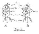
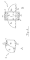
- FIGS. 1A to 3B show perspective views from above for three exemplary embodiments of the invention Storage system 1 in the closed, ie non-pivoted state (FIGS. 1A, 2A, 3A) or in the open or pivoted state (FIGS. 1B, 2B, 3B).
- Three storage containers 2a, 2b, 2c are arranged vertically one above the other on a holding rod 3, which in the first two exemplary embodiments are fastened to a wall by means of so-called fastening webs 5 at the upper and lower ends of the holding rod 3.
- all containers consist of cube-shaped boxes with an identical base.
- the ceiling surfaces 12 or tops 12 are omitted, so that each box can only be accessed from above.
- the shelf compartment occurs with a missing front wall and a missing ceiling wall 12, the side walls 8a and 8b being designed in the form of a segment of a circle, this applies to FIGS. 2A and 2B the upper storage container 2a and in FIGS. 3A and 3B the two upper storage containers 2a, 2b.
- All of the storage containers shown in the exemplary embodiments shown in FIGS. 1A to 3B have holding webs 4 provided with three holes 13 on the upper and lower sides 12 and 11 in the region of the rear wall 9 of the storage container 2a, 2b or 2c.
- the holding holes 3, which are arranged on the right-hand side in each case, are penetrated by the holding rod 3, which serves here as a pivot axis.
- the storage container 2b is pivoted in the middle by 90 o to the right, so that all three storage containers 2a, 2b, 2c can be accessed at the same time because they are open at the top.
- the holding holes 3 penetrate the receiving holes 13 of the webs 4 of the containers 2a, 2b, 2c arranged on the left side.
- the central storage container is also pivoted by 90 o to open the entire storage system, to the left.
- the mean intake holes are each occupied 13 of the support rod 3 and in Fig. 3B is the average storage container of a shelf compartment 180 o pivoted 2b in the form of backwards, so that the lowermost container 2c, here in the form of a box, free access.
- 3A and 3B show that the holding rod 3 for holding and pivoting the storage containers 2a, 2b, 2c can also be fixed to a trolley 5.
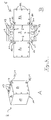
- 4A and 4B show in detail an already folded storage container 2 prepared for installation, here in the form of a box open at the top.
- 4B shows the container raw part 6.
- This container raw part consists of a rear wall 9, side walls 8a, 8b, and also of holding webs arranged on the upper and lower sides 12 and 11 of the rear wall 9 4.
- the holding webs 4 have three receiving holes 13 for receiving the holding rod 3.
- FIG. 5 shows a storage container 2 in the form of a drawer, the basic container 2 being constructed in an analogous manner to the box-shaped container described in FIGS. 4A and 4B.
- the drawer insert 23 appears partially pulled out. It can also be constructed in an analogous manner to the box, but it is also possible to use prefabricated, box-shaped parts in a suitable form and in particular also to provide roller inserts or roller rails.
- FIG. 6A and 6B show the shelf part already briefly described above with access from above and from the front, or its raw container part.
Landscapes
- Warehouses Or Storage Devices (AREA)
- Container Filling Or Packaging Operations (AREA)
- Details Of Rigid Or Semi-Rigid Containers (AREA)
Applications Claiming Priority (2)
| Application Number | Priority Date | Filing Date | Title |
|---|---|---|---|
| DE29608833U DE29608833U1 (de) | 1996-05-15 | 1996-05-15 | Ablagesystem zur Ablage von Gegenständen |
| DE29608833U | 1996-05-15 |
Publications (2)
| Publication Number | Publication Date |
|---|---|
| EP0807389A2 true EP0807389A2 (fr) | 1997-11-19 |
| EP0807389A3 EP0807389A3 (fr) | 1999-09-15 |
Family
ID=8024041
Family Applications (1)
| Application Number | Title | Priority Date | Filing Date |
|---|---|---|---|
| EP97106111A Withdrawn EP0807389A3 (fr) | 1996-05-15 | 1997-04-14 | Système de rangement pour ranger des objets |
Country Status (2)
| Country | Link |
|---|---|
| EP (1) | EP0807389A3 (fr) |
| DE (1) | DE29608833U1 (fr) |
Cited By (1)
| Publication number | Priority date | Publication date | Assignee | Title |
|---|---|---|---|---|
| EP1222878A1 (fr) * | 2001-01-12 | 2002-07-17 | Pintus, Sylviane | Meuble à modules de rangement s'actionnant par un mouvement de rotation à indexation |
Families Citing this family (3)
| Publication number | Priority date | Publication date | Assignee | Title |
|---|---|---|---|---|
| DE29621555U1 (de) * | 1996-12-12 | 1997-02-27 | Utz, Walter, 88361 Altshausen | Ablage zur Aufnahme von Gegenständen |
| US8528751B2 (en) * | 2010-09-23 | 2013-09-10 | Harry And David, Llc | Gift box with individually rotatable compartments |
| CN113525881B (zh) * | 2021-09-01 | 2022-12-02 | 山东柏源技术有限公司 | 一种海洋运输用储物装置 |
Family Cites Families (5)
| Publication number | Priority date | Publication date | Assignee | Title |
|---|---|---|---|---|
| US3203124A (en) * | 1963-02-05 | 1965-08-31 | Stoessel Henry Kurt | Collapsible display device |
| FR1477261A (fr) * | 1966-04-25 | 1967-04-14 | Horsters Bueroorganisation Fa | Armoire pour classement suspendu vertical |
| GB2080766B (en) * | 1980-07-28 | 1984-06-20 | Panavista Ltd | Storage container assembly |
| US4579233A (en) * | 1984-08-09 | 1986-04-01 | James Hepp | Adjustable knockdown tray assembly |
| DE29501370U1 (de) * | 1995-01-28 | 1995-04-13 | Ponholzer, Anette Franziska, 24103 Kiel | Zerlegbares Schrankmöbel |
-
1996
- 1996-05-15 DE DE29608833U patent/DE29608833U1/de not_active Expired - Lifetime
-
1997
- 1997-04-14 EP EP97106111A patent/EP0807389A3/fr not_active Withdrawn
Cited By (1)
| Publication number | Priority date | Publication date | Assignee | Title |
|---|---|---|---|---|
| EP1222878A1 (fr) * | 2001-01-12 | 2002-07-17 | Pintus, Sylviane | Meuble à modules de rangement s'actionnant par un mouvement de rotation à indexation |
Also Published As
| Publication number | Publication date |
|---|---|
| EP0807389A3 (fr) | 1999-09-15 |
| DE29608833U1 (de) | 1996-08-14 |
Similar Documents
| Publication | Publication Date | Title |
|---|---|---|
| CH684992A5 (de) | Vorrichtung zur Ablage von Compact-Discs. | |
| DE69116400T2 (de) | Möbelverbindung | |
| WO2005024318A1 (fr) | Compartiment de porte pour refrigerateur | |
| EP2063735B1 (fr) | Table, notamment table d'écolier | |
| EP0807389A2 (fr) | Système de rangement pour ranger des objets | |
| CH617334A5 (fr) | ||
| WO1995012793A1 (fr) | Meuble, compose d'un corps avec porte, en particulier refrigerateur ou buffet a vaisselle | |
| DE102012007306B4 (de) | Küchenschrank mit mehreren in einemSchrankfach angeordneten Platten | |
| EP1264564B1 (fr) | Corps de meuble | |
| DE20006296U1 (de) | Einrichtung für die Aufnahme einer Mehrzahl von Behältern | |
| EP1334674B1 (fr) | Meuble de cuisine, en particulier une armoire suspendue | |
| DE2645481C3 (de) | Ständer für Gewürzbehälter o.dgl | |
| DE19718274C2 (de) | Bevorratungsvorrichtung für Arzneimittel in einem Schrank | |
| DE29911784U1 (de) | Vorrichtung zur Präsentation und Bevorratung von schalenförmigen Elementen, insbesondere Duschtassen | |
| DE9209982U1 (de) | Vorrichtung zum Ablegen und Entnehmen von quaderförmigen Gegenständen | |
| DE20009853U1 (de) | Arbeitsplatz-Container | |
| WO1995005103A1 (fr) | Appareil de distribution de courant pour meubles de bureau | |
| DE4419809A1 (de) | Schreibtisch mit vergrößerungsfähiger Platte | |
| DE20010930U1 (de) | Möbelkorpus | |
| DE29805224U1 (de) | Schrank | |
| DE7936380U1 (de) | Praesentationsmuster fuer moebelfronten | |
| AT527844A4 (de) | Aufsatzvorrichtung für eine Schublade | |
| DE1946660C (de) | Hohenverstellbarer Schultisch | |
| DE29708337U1 (de) | Regal bzw. Regalsystem | |
| DE1943554U (de) | Aufstellbare einbauschrankeinheit. |
Legal Events
| Date | Code | Title | Description |
|---|---|---|---|
| PUAI | Public reference made under article 153(3) epc to a published international application that has entered the european phase |
Free format text: ORIGINAL CODE: 0009012 |
|
| AK | Designated contracting states |
Kind code of ref document: A2 Designated state(s): AT BE CH DE FR IT LI LU NL |
|
| PUAL | Search report despatched |
Free format text: ORIGINAL CODE: 0009013 |
|
| AK | Designated contracting states |
Kind code of ref document: A3 Designated state(s): AT BE CH DE FR IT LI LU NL |
|
| RIC1 | Information provided on ipc code assigned before grant |
Free format text: 6A 47B 49/00 A, 6A 47B 43/02 B, 6A 47B 47/06 B |
|
| STAA | Information on the status of an ep patent application or granted ep patent |
Free format text: STATUS: THE APPLICATION IS DEEMED TO BE WITHDRAWN |
|
| 18D | Application deemed to be withdrawn |
Effective date: 20000704 |