EP0807389A2 - Storing system for storing of objects - Google Patents
Storing system for storing of objects Download PDFInfo
- Publication number
- EP0807389A2 EP0807389A2 EP97106111A EP97106111A EP0807389A2 EP 0807389 A2 EP0807389 A2 EP 0807389A2 EP 97106111 A EP97106111 A EP 97106111A EP 97106111 A EP97106111 A EP 97106111A EP 0807389 A2 EP0807389 A2 EP 0807389A2
- Authority
- EP
- European Patent Office
- Prior art keywords
- storage
- container
- holding
- storage system
- containers
- Prior art date
- Legal status (The legal status is an assumption and is not a legal conclusion. Google has not performed a legal analysis and makes no representation as to the accuracy of the status listed.)
- Withdrawn
Links
Images


Classifications
-
- A—HUMAN NECESSITIES
- A47—FURNITURE; DOMESTIC ARTICLES OR APPLIANCES; COFFEE MILLS; SPICE MILLS; SUCTION CLEANERS IN GENERAL
- A47B—TABLES; DESKS; OFFICE FURNITURE; CABINETS; DRAWERS; GENERAL DETAILS OF FURNITURE
- A47B49/00—Revolving cabinets or racks; Cabinets or racks with revolving parts
- A47B49/004—Cabinets with compartments provided with trays revolving on a vertical axis
Definitions
- the invention relates to a storage system for storing objects according to the preamble of claim 1.
- the compartments and drawers are usually arranged one above the other, so that when a drawer is pulled out, access to this pulled-out drawer is unhindered, but at the same time the actuation of the other drawers, the inspection of their contents or even access to them becomes impossible.
- Such devices are known in particular in the case of designer furniture for hairdressing or cosmetic salons in the form of make-up and utensil columns, but are also increasingly being used in private and domestic areas, in particular in bathrooms and toilets.
- a problem with these known storage systems with compartments or containers which can be pivoted relative to one another about a vertical axis is that, in particular, a large number of customers has not been able to be opened up to date because such known storage systems have previously been made from solid materials and thus in the private sector, especially in confined spaces a rental apartment were perceived as too bulky, which greatly restricted their applicability in the domestic area.
- the invention has for its object to provide a storage system for storing objects, which allows before installing the simplest possible transport of items of filing systems and which also allows for the installation of a particularly flexible handling in confined spaces.
- the storage containers for installation in the storage system are each foldable or bendable from an essentially one-piece, plate-shaped container blank into the container shapes intended for installation.
- the container raw parts consist in particular of a bendable material and have predetermined folding edges or bending edges.
- These folded edges can be designed as thinned, pre-pressed areas or else as pre-perforated lines.
- the respective container raw part of a storage container comprises at least two side walls and a rear wall, with wall, ceiling or floor parts possibly also being provided which can be attached to the container folding part already folded to complete the storage container to be installed.
- the solution to the object preferably provides that the pivot axis of the respective storage containers can be designed to be freely selectable when they are installed at one of several possible positions in the region of one of the walls of the installed storage container.
- variable swivel axes individually provides a particularly flexible arrangement of the storage containers for each storage container, so that even in the most confined spaces, as is e.g. in a typical rental apartment, saves a lot of space while at the same time flexibly accommodating and handling a large number of everyday items.
- a particularly simple embodiment of the storage system results from the design of the holding and pivoting device for each storage container essentially on the raw container part of the respective storage container itself. the attachment of any hinges or the like, which represents a further simplification in the construction and assembly of the storage system according to the invention by the end customer.
- a further simplification of the holding and pivoting device results from the fact that in the region, in particular the rear wall, a pair of substantially identical holding webs is formed, which face each other and which are formed perpendicular to the respective rear wall.
- the flexibility of the pivot axis positioning results from the fact that a plurality of corresponding receiving holes are provided on the holding webs for receiving the holding rod, the diameter of the receiving holes essentially corresponding to the outer diameter of the holding rod, which makes pivoting of the individual storage containers particularly free of play possible.
- the embodiment of the storage system according to the invention is particularly space-saving if the holding webs are designed to accommodate the holding rod to the interior of the storage container, because then the holding rod virtually penetrates the respective storage container, in particular in the edge region of the rear wall.
- the holding webs are each formed on the top or on the bottom of the respective storage container, because then the interior of the storage container can be used particularly effectively because the size of the interior is then not noticeably restricted by the holding webs.
- this container is secured against slipping downwards. This is ensured in a particularly simple manner in that a clamping ring is formed on the holding rod, which fixes the bottom container against vertical displacement.
- the storage container filters In order to further ensure easy swiveling of the successive storage containers and, moreover, to prevent them from tilting when swiveling, provision is made for the storage container filters to be spaced apart from one another by means of spacer rings.
- a storage container here is generally understood to be any container that can be equipped with such a pivoting and holding device and that is also used for receiving, storing and storing utensils, regardless of the shape of the base of the container.
- a very space-saving arrangement which is also visually appealing, results from the same, in particular rectangular, base area of the storage containers.
- such a storage container can be designed as a box, this box not having a ceiling plate.
- a compartment in the form of a shelf compartment is also provided, with either only one front wall being missing or the cover and front wall being omitted.
- the formation of known drawers is particularly advantageous with drawer inserts, with safeguards against falling out also being provided.
- a particularly simple assembly of the storage system by the end customer is obtained if the material for the container raw parts is plastic or bendable, and particularly inexpensive configurations result when using e.g. Cardboard, pressed cardboard, plastic or metal.
- any bendable or plastically deformable material be it transparent or opaque, can be provided as long as simple assembly and, in particular, simple folding of the container raw parts is possible without special tools or special effort.
- wall, ceiling and floor parts which may be added from wood, metal, glass, plastic or the like.
- a greater material thickness is also provided in order to give the entire storage system greater mechanical stability.
- the holding and fastening device for the storage system is advantageous to design as a pair of fastening webs for spaced holding, in particular on a wall.
- the fastening webs are to be formed in particular in the end regions of the holding rod in order to accommodate the largest space in the holding rod for accommodating the largest possible number of storage containers keep clear.
- the fastening webs themselves can be fastened using conventional fixing means, such as screws, nails, rivets or the like.
- the holding and fastening device for the storage system in particular in the hobby and workshop area, it is advantageous to design the holding and fastening device for the storage system according to the invention as a floor frame. It is then also advantageous to provide this base frame with a counterweight in order to make the center of gravity of the entire storage system as deep as possible and thus to prevent it from tipping over, in particular when the storage containers are pivoted. Furthermore, there is a particularly flexible and widely usable storage system if the base frame is designed as a frame with rollers, because then the entire storage system can be moved as desired at the location where it is to be used.
- the support rod as a telescopic rod, because then the individual storage containers can also be adjusted in height, and also because the entire storage system between the floor and the ceiling of the room in which the storage system is installed can be extended by extending the telescopic rod should be attached and fixed.
- the flexibility of the arrangement of the storage containers in the storage system according to the invention is underlined by the different positions of the pivot axis provided for the respective storage containers. If, for example, three holes are provided for receiving the support rod in the support web, all storage containers of a storage system can have their pivot axis defined on one and the same hole or they can also be offset with respect to one another have defined pivot axes, so that in the non-pivoted state at least some of the containers are freely accessible for access and inspection.
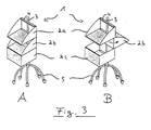
- FIGS. 1A to 3B show perspective views from above for three exemplary embodiments of the invention Storage system 1 in the closed, ie non-pivoted state (FIGS. 1A, 2A, 3A) or in the open or pivoted state (FIGS. 1B, 2B, 3B).
- Three storage containers 2a, 2b, 2c are arranged vertically one above the other on a holding rod 3, which in the first two exemplary embodiments are fastened to a wall by means of so-called fastening webs 5 at the upper and lower ends of the holding rod 3.
- all containers consist of cube-shaped boxes with an identical base.
- the ceiling surfaces 12 or tops 12 are omitted, so that each box can only be accessed from above.
- the shelf compartment occurs with a missing front wall and a missing ceiling wall 12, the side walls 8a and 8b being designed in the form of a segment of a circle, this applies to FIGS. 2A and 2B the upper storage container 2a and in FIGS. 3A and 3B the two upper storage containers 2a, 2b.
- All of the storage containers shown in the exemplary embodiments shown in FIGS. 1A to 3B have holding webs 4 provided with three holes 13 on the upper and lower sides 12 and 11 in the region of the rear wall 9 of the storage container 2a, 2b or 2c.
- the holding holes 3, which are arranged on the right-hand side in each case, are penetrated by the holding rod 3, which serves here as a pivot axis.
- the storage container 2b is pivoted in the middle by 90 o to the right, so that all three storage containers 2a, 2b, 2c can be accessed at the same time because they are open at the top.
- the holding holes 3 penetrate the receiving holes 13 of the webs 4 of the containers 2a, 2b, 2c arranged on the left side.
- the central storage container is also pivoted by 90 o to open the entire storage system, to the left.
- the mean intake holes are each occupied 13 of the support rod 3 and in Fig. 3B is the average storage container of a shelf compartment 180 o pivoted 2b in the form of backwards, so that the lowermost container 2c, here in the form of a box, free access.
- 3A and 3B show that the holding rod 3 for holding and pivoting the storage containers 2a, 2b, 2c can also be fixed to a trolley 5.
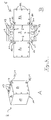
- 4A and 4B show in detail an already folded storage container 2 prepared for installation, here in the form of a box open at the top.
- 4B shows the container raw part 6.
- This container raw part consists of a rear wall 9, side walls 8a, 8b, and also of holding webs arranged on the upper and lower sides 12 and 11 of the rear wall 9 4.
- the holding webs 4 have three receiving holes 13 for receiving the holding rod 3.
- FIG. 5 shows a storage container 2 in the form of a drawer, the basic container 2 being constructed in an analogous manner to the box-shaped container described in FIGS. 4A and 4B.
- the drawer insert 23 appears partially pulled out. It can also be constructed in an analogous manner to the box, but it is also possible to use prefabricated, box-shaped parts in a suitable form and in particular also to provide roller inserts or roller rails.
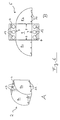
- FIG. 6A and 6B show the shelf part already briefly described above with access from above and from the front, or its raw container part.
Landscapes
- Warehouses Or Storage Devices (AREA)
- Details Of Rigid Or Semi-Rigid Containers (AREA)
- Container Filling Or Packaging Operations (AREA)
Abstract
Das Ablagesystem zur Ablage von Gegenständen umfaßt eine auf einer linearen Haltestange verschwenkbar und übereinander angeordnete Mehrzahl von Ablagebehältern, die unabhängig voneinander halterbar und verschwenkbar sind. Die Ablagebehälter sind jeweils aus einem einstückigen plattenförmigen Behälterrohteil biegbaren Materials mit vorbestimmten Biegekanten biegbar. Das Behälterrohteil umfaßt mindestens zwei Seitenwände und eine Rückwand des Ablagebehälters, wobei am gefalteten Behälterrohteil zur Vervollständigung Wand-, Decken- oder Bodenteile anbringbar sind. Die Schwenkachse für die Ablagebehälter ist bei deren Installation an einer von mehreren möglichen Positionen im Bereich einer der Wände des installierten Ablagebehälters frei wählbar.
Description
Die Erfindung betrifft ein Ablagesystem zur Ablage von Gegenständen gemäß dem Oberbegriff des Anspruchs 1.The invention relates to a storage system for storing objects according to the preamble of claim 1.
Im Haushalts- und Hobbybereich, aber auch im Bereich der manuell tätigen Berufe, der Forschung und Entwicklung und im Bereich der kosmetischen und medizinischen Berufe sind die verschiedensten Ablagesystem zur Ablage und Aufnahme von Gegenständen und insbesondere von Kleinstutensilien bekannt. So finden sich insbesondere für handwerkliche Berufe z.B. in Werkbänke integrierbare mit Rollschubläden versehene Werkzeug- und Materialschränke mit einer Vielzahl von Schubläden und Fächern zur Aufnahme des für den jeweiligen Bereich notwendigen Materials oder Werkzeugs. Bekannt sind ferner z.B. im kosmetischen Sektor oder auch im Bereich von Klinik und Diagnostik sogenannte fahrbare Beistelltische oder Konsolen, welche ebenfalls eine Vielzahl von Fächern und Rollschubläden aufweisen.In the household and hobby area, but also in the area of manual occupations, research and development and in the area of cosmetic and medical professions, a wide variety of storage systems for storing and storing objects and especially small utensils are known. For example, for craft trades, for example Tool and material cabinets with roller drawers that can be integrated into workbenches and have a large number of drawers and compartments to hold the material or tools required for the respective area. Also known are e.g. In the cosmetic sector or in the area of clinics and diagnostics, so-called mobile side tables or consoles, which also have a large number of compartments and roller drawers.
Bei diesen bekannten Einrichtungen sind die Fächer und Schubläden in der Regel übereinander angeordnet, so daß beim Herausziehen eines Schubfaches zwar der Zugriff auf dieses herausgezogene Schubfach ungehindert möglich ist, aber gleichzeitig die Betätigung der anderen Schubfächer, die Inaugenscheinnahme deren Inhalts oder gar der Zugriff auf sie unmöglich wird. Es ist aber häufig erwünscht, Zugriff auf mehrere Fächer, Behälter oder Schubfächer gleichzeitig zu haben, um ohne große manuelle oder gedankliche Tätigkeit die in den Schubfächern enthaltenen Gegenstände, insbesondere unter ungehinderter Inaugenscheinnahme, auswählen und entnehmen zu können.In these known devices, the compartments and drawers are usually arranged one above the other, so that when a drawer is pulled out, access to this pulled-out drawer is unhindered, but at the same time the actuation of the other drawers, the inspection of their contents or even access to them becomes impossible. However, it is often desirable to have access to several compartments, containers or drawers at the same time, in order to be able to select and remove the objects contained in the drawers without much manual or intellectual activity, in particular with an unobstructed inspection.
Um diesem Anliegen entgegenzukommen, wurden Ablage- und Regalsysteme entwickelt, bei denen die einzelnen Fächer oder Behälter im wesentlichen vertikal übereinander angeordnet sind und um eine im wesentlichen senkrechte und gemeinsame Schwenkachse gegeneinander verdreht werden können, so daß der Zugriff auf mehrere Behälter oder Fächer gleichzeitig und ungehindert erfolgen kann.To meet this concern, storage and shelving systems were developed in which the individual compartments or containers are arranged substantially vertically one above the other and can be rotated against each other about a substantially vertical and common pivot axis, so that access to several containers or compartments simultaneously and can be done freely.
Derartige Einrichtungen sind insbesondere bei Designermöbel für Friseur- oder Kosmetiksalons in Form von Schmink- und Utensiliensäulen bekannt, werden aber auch im privaten und häuslichen Bereich, insbesondere in Bad und WC vermehrt eingesetzt.Such devices are known in particular in the case of designer furniture for hairdressing or cosmetic salons in the form of make-up and utensil columns, but are also increasingly being used in private and domestic areas, in particular in bathrooms and toilets.
Bei diesen bekannten Ablagesystemen mit gegeneinander um eine vertikale Achse verschwenkbaren Fächern oder Behältern besteht ein Problem darin, daß insbesondere ein großer Kundenkreis bisher nicht erschlossen werden konnte, weil derartige bekannte Ablagesystem bisher aus massiven Materialien gearbeitet waren und somit im privaten Bereich, insbesondere im engen Raum einer Mietwohnung als zu sperrig empfunden wurden, was ihre Anwendbarkeit im häuslichen Bereich stark einschränkte.A problem with these known storage systems with compartments or containers which can be pivoted relative to one another about a vertical axis is that, in particular, a large number of customers has not been able to be opened up to date because such known storage systems have previously been made from solid materials and thus in the private sector, especially in confined spaces a rental apartment were perceived as too bulky, which greatly restricted their applicability in the domestic area.
Ferner sind die bekannten verschwenkbaren Ablagesysteme in ihrer Handhabung auf engem Raum deshalb stark eingeschränkt, weil sich trotz der Verschwenkbarkeit der einzelnen Schubfach- oder Behältereinheiten die Bedienung als zu unflexibel erweist, was sich insbesondere dann bemerkbar macht, wenn nur begrenzter Raum zur Verfügung steht, welcher vom potentiellen Kunden möglichst optimal genutzt werden soll.Furthermore, the known pivotable storage systems are severely restricted in their handling in a narrow space because, despite the pivotability of the individual drawer or container units, the operation proves to be too inflexible, which is particularly noticeable when only limited space is available, which should be used as optimally as possible by the potential customer.
Ein weiteres Problem ergibt sich bei einer bekannten Ablageeinrichtung mit verschwenkbaren Schubfächern oder Behältereinheiten dadurch, daß der Antransport eines derartigen Möbels aufgrund der massiven und sperrigen Bauweise erschwert wird. Der große Materialaufwand bei den bekannten Ablagesystemen fordert zudem einen für den Kunden oft in keinem Verhältnis zum Nutzen eines derartigen Möbels stehenden Preis.Another problem arises in a known storage device with pivotable drawers or container units in that the transport of such a piece of furniture is made more difficult due to the massive and bulky construction. The large amount of material used in the known storage systems also requires a price that is often disproportionate to the benefit of such furniture for the customer.
Der Erfindung liegt die Aufgabe zugrunde, ein Ablagesystem zur Ablage von Gegenständen zu schaffen, welches vor der Installation einen möglichst einfachen Transport der Einzelteile des Ablagesysteme ermöglicht und welches nach der Installation eine besonders flexible Handhabung auch auf engstem Raum gestattet.The invention has for its object to provide a storage system for storing objects, which allows before installing the simplest possible transport of items of filing systems and which also allows for the installation of a particularly flexible handling in confined spaces.
Die Aufgabe wird erfindungsgemäß durch ein Ablagesystem gemäß dem kennzeichnenden Teil des Anspruchs 1 gelöst.The object is achieved according to the invention by a storage system according to the characterizing part of claim 1.
Bevorzugte Ausführungsformen des erfindungsgemäßen Ablagesystems sind Gegenstand der Unteransprüche.Preferred embodiments of the storage system according to the invention are the subject of the dependent claims.
Die Lösung der Aufgabe sieht vor, daß beim erfindungsgemäßen Ablagesystem die Ablagebehälter zur Installation im Ablagesystem jeweils aus einem im wesentlichen einstückigen, plattenförmigen Behälterrohteil in die zur Installation bestimmte Behälterformen faltbar oder biegbar sind. Die Behälterrohteile bestehen insbesondere aus einem biegbaren Material und weisen vorbestimmte Faltkanten oder Biegekanten auf.The solution to the problem provides that in the storage system according to the invention the storage containers for installation in the storage system are each foldable or bendable from an essentially one-piece, plate-shaped container blank into the container shapes intended for installation. The container raw parts consist in particular of a bendable material and have predetermined folding edges or bending edges.
Diese Faltkanten können als verdünnte, vorgepreßte Bereiche oder aber auch als vorperforierte Linien ausgebildet sein.These folded edges can be designed as thinned, pre-pressed areas or else as pre-perforated lines.
Das jeweilige Behälterrohteil eines Ablagebehälters umfaßt mindestens zwei Seitenwände und eine Rückwand, wobei gegebenenfalls noch Wand-, Decken- oder Bodenteile vorgesehen sind, welche zur Vervollständigung des zu installierenden Ablagebehälters am bereits gefalteten Behälterrohteil anbringbar sind.The respective container raw part of a storage container comprises at least two side walls and a rear wall, with wall, ceiling or floor parts possibly also being provided which can be attached to the container folding part already folded to complete the storage container to be installed.
Ferner sieht die Lösung der Aufgabe vorzugsweise vor, daß die Schwenkachse der jeweiligen Ablagebehälter bei deren Installation an einer von mehreren möglichen Positionen im Bereich einer der Wände des installierten Ablagebehälters frei wählbar ausbildbar ist.Furthermore, the solution to the object preferably provides that the pivot axis of the respective storage containers can be designed to be freely selectable when they are installed at one of several possible positions in the region of one of the walls of the installed storage container.
Durch das Vorsehen von Behälterrohteilen und von gegebenenfalls noch hinzuzufügenden Wand-, Decken- oder Bodenteilen, ist eine Anlieferung des erfindungsgemäßen Ablagesystems oder ein Transport denkbar einfach, so daß es beim Umzug oder beim Kauf in einem Möbel-Abholmarkt für den mit keinen besonderen Transportmöglichkeiten versehenen Endkunden keine nennenswerten Probleme gibt.By providing raw container parts and any wall, ceiling or floor parts that may need to be added, delivery of the storage system according to the invention or transport is extremely simple, so that it is not provided with any special transport options when moving or buying in a furniture pick-up market End customers there are no significant problems.
Ferner bietet das erfindungsgemäße System der variablen Schwenkachsen für jeden Ablagebehälter einzeln eine besonders flexible Anordnung der Ablagebehälter, so daß auch auf engstem Raum, wie er sich z.B. in einer typischen Mietwohnung darstellt, eine große Platzersparnis bei gleichzeitiger flexibler Unterbringung und Handhabung einer Vielzahl von täglichen Gebrauchsgegenständen einstellt.Furthermore, the system according to the invention of the variable swivel axes individually provides a particularly flexible arrangement of the storage containers for each storage container, so that even in the most confined spaces, as is e.g. in a typical rental apartment, saves a lot of space while at the same time flexibly accommodating and handling a large number of everyday items.
Zudem ist die Handhabung eines derartigen Ablagesystems beim Aufbau und bei der Installation besonders einfach, da durch die vorgefertigten Falt- und Biegekanten keinerlei Spezialwerkzeuge oder ein besonderes handwerkliches Geschick durch den Endkunden benötigt werden.In addition, the handling of such a storage system is particularly easy during assembly and installation, since the prefabricated folding and bending edges mean that no special tools or special manual skills are required by the end customer.
Eine besonders einfache Ausgestaltung des Ablagesystems ergibt sich durch das Ausbilden der Halte- und Verschwenkeinrichtung für jeden Ablagebehälter im wesentlichen am Behälterrohteil des jeweiligen Ablagebehälters selbst. Dann nämlich entfällt z.B. das Anbringen etwaiger Scharniere oder dergleichen, was eine weitere Vereinfachung beim Aufbau und beim Zusammensetzen des erfindungsgemäßen Ablagesystems durch den Endkunden darstellt.A particularly simple embodiment of the storage system results from the design of the holding and pivoting device for each storage container essentially on the raw container part of the respective storage container itself. the attachment of any hinges or the like, which represents a further simplification in the construction and assembly of the storage system according to the invention by the end customer.
Eine weitere Vereinfachung der Halte- und Verschwenkeinrichtung ergibt sich dadurch, daß im Bereich, insbesondere der Rückwand, ein Paar im wesentlichen gleicher Haltestege ausgebildet ist, die sich gegenüberstehen und die senkrecht zur jeweiligen Rückwand ausgebildet sind. Die Flexibilität der Verschwenkachsenpositionierung ergibt sich dadurch, daß eine Mehrzahl korrespondierender Aufnahmelöcher an den Haltestegen zur Aufnahme der Haltestange vorgesehen sind, wobei der Durchmesser der Aufnahmelöcher im wesentlichen dem Außendurchmesser der Haltestange entspricht, was ein besonders spielfreies Verschwenken der einzelnen Ablagebehälter möglich macht.A further simplification of the holding and pivoting device results from the fact that in the region, in particular the rear wall, a pair of substantially identical holding webs is formed, which face each other and which are formed perpendicular to the respective rear wall. The flexibility of the pivot axis positioning results from the fact that a plurality of corresponding receiving holes are provided on the holding webs for receiving the holding rod, the diameter of the receiving holes essentially corresponding to the outer diameter of the holding rod, which makes pivoting of the individual storage containers particularly free of play possible.
Durch diese Anordnung sind keine weiteren Scharnier- oder Verschwenkeinrichtungen nötig, weil die Haltestange selbst als Dreh- oder Verschwenkachse fungiert und zusätzlich die einzelnen Ablagebehälter gegen ein Verkippen oder Verrutschen hält.With this arrangement, no further hinge or pivoting devices are necessary because the holding rod itself acts as a pivoting or pivoting axis and additionally holds the individual storage containers against tilting or slipping.
Besonders platzsparend ist die Ausführungsform des erfindungsgemäßen Ablagesystems, wenn die Haltestege zur Aufnahme der Haltestange zum Innenraum des Ablagebehälters ausgebildet sind, denn dann durchdringt die Haltestange quasi den jeweiligen Ablagebehälter, und zwar insbesondere im Randbereich der Rückwand.The embodiment of the storage system according to the invention is particularly space-saving if the holding webs are designed to accommodate the holding rod to the interior of the storage container, because then the holding rod virtually penetrates the respective storage container, in particular in the edge region of the rear wall.
Es ist von Vorteil, daß die Haltestege jeweils an der Ober- bzw. an der Unterseite des jeweiligen Ablagebehälters ausgebildet sind, weil dann der Innenraum des Ablagebehälters besonders effektiv genutzt werden kann, weil die Größe des Innenraums durch die Haltestege dann nicht merklich eingeschränkt wird.It is advantageous that the holding webs are each formed on the top or on the bottom of the respective storage container, because then the interior of the storage container can be used particularly effectively because the size of the interior is then not noticeably restricted by the holding webs.
Um auch den untersten Ablagebehälter drehbar zu lagern, ist es vorgesehen, diesen Behälter gegen ein Abrutschen nach unten zu sichern. Dies wird besonders einfach dadurch gewährleistet, daß an der Haltestange ein Klemmring ausgebildet wird, der den untersten Behälter gerade gegen ein vertikales Verschieben fixiert.In order to rotatably support the lowest storage container, it is provided that this container is secured against slipping downwards. This is ensured in a particularly simple manner in that a clamping ring is formed on the holding rod, which fixes the bottom container against vertical displacement.
Um ferner ein leichtes Verschwenken der aufeinanderfolgenden Ablagebehälter zu gewährleisten und darüber hinaus ein Verkanten beim Verschwenken zu verhindern, ist es vorgesehen, die Ablagebehfilter mittels Distanzringe gegegeneinander beabstandet auszubilden.In order to further ensure easy swiveling of the successive storage containers and, moreover, to prevent them from tilting when swiveling, provision is made for the storage container filters to be spaced apart from one another by means of spacer rings.
Als Ablagebehälter wird hier ganz allgemein jeder Behälter verstanden, der mit einer derartigen Verschwenk- und Halteeinrichtung ausgestattet werden kann und der darüber hinaus der Aufnahme, Ablage und Lagerung von Utensilien dient, und zwar ganz unabhängig von der Form der Grundfläche des Behälters. Eine sehr platzsparende Anordnung, die auch optisch gefällig ist, ergibt sich bei gleicher, insbesondere rechteckiger Grundfläche der Ablagebehälter.As a storage container here is generally understood to be any container that can be equipped with such a pivoting and holding device and that is also used for receiving, storing and storing utensils, regardless of the shape of the base of the container. A very space-saving arrangement, which is also visually appealing, results from the same, in particular rectangular, base area of the storage containers.
Insbesondere kann ein derartiger Ablagebehälter als Box ausgebildet sein, wobei diese Box keine Deckenplatte aufweist. Ferner ist aber auch ein Fach in Form eines Regalfachs vorgesehen, wobei entweder nur eine Vorderwand fehlt, oder aber Deckel und Vorderwand fortgelassen sind. Besonders vorteilhaft ist das Ausbilden bekannter Schubfächer mit Schubfacheinsätzen, wobei darüber hinaus dann auch Sicherungen gegen das Herausfallen vorgesehen sind.In particular, such a storage container can be designed as a box, this box not having a ceiling plate. Furthermore, a compartment in the form of a shelf compartment is also provided, with either only one front wall being missing or the cover and front wall being omitted. The formation of known drawers is particularly advantageous with drawer inserts, with safeguards against falling out also being provided.
Ein besonders einfaches Zusammensetzen des Ablagesystems durch den Endkunden ergibt sich, wenn das Material für die Behälterrohteile plastisch oder biegbar ausgebildet ist, und besonders preisgünstigte Ausgestaltungen ergeben sich bei der Verwendung von z.B. Pappe, Preßpappe, Kunststoff oder auch von Metallen. Generell kann aber jedes biegbare oder plastisch verformbare Material, sei es transparent oder opak, vorgesehen sein, so lange nur ein einfaches Zusammensetzen und insbesondere ein einfaches Falten der Behälterrohteile ohne Spezialwerkzeug oder besonderen Kraftaufwand möglich ist.A particularly simple assembly of the storage system by the end customer is obtained if the material for the container raw parts is plastic or bendable, and particularly inexpensive configurations result when using e.g. Cardboard, pressed cardboard, plastic or metal. In general, however, any bendable or plastically deformable material, be it transparent or opaque, can be provided as long as simple assembly and, in particular, simple folding of the container raw parts is possible without special tools or special effort.
Darüber hinaus ist es von Vorteil, die gegebenenfalls hinzuzufügenden Wand-, Decken- und Bodenteile aus Holz, Metall, Glas, Kunststoff oder dergleichen auszubilden. Dabei ist ferner eine größere Materialstärke vorgesehen, um dem gesamten Ablagesystem eine größere mechanische Stabilität zu geben. Zur Einfügung der hinzuzufügenden Wand-, Decken- oder Bodenteile sind entsprechende Aufnahmeschienen bzw. Löcher zur Aufnahme von Fixiermitteln, insbesondere von Schrauben, Nieten oder Nägeln oder dergleichen, in den Seitenwänden des Behälterrohteils vorgesehen.In addition, it is advantageous to design the wall, ceiling and floor parts which may be added from wood, metal, glass, plastic or the like. A greater material thickness is also provided in order to give the entire storage system greater mechanical stability. Corresponding mounting rails or holes for receiving fixing means, in particular screws, rivets or nails or the like, are provided in the side walls of the raw container part for inserting the wall, ceiling or floor parts to be added.
Um das gesamte Ablagesystem stabil unterzubringen, ist es von Vorteil, die Halte- und Befestigungseinrichtung für das Ablagesystem als ein Paar Befestigungsstege zum beabstandeten Haltern, insbesondere an einer Wand, auszubilden. Die Befestigungsstege sind insbesondere in den Endbereichen der Haltestange auszubilden, um den größten Raum der Haltestange zur Unterbringung einer möglichst großen Zahl von Ablagebehältern freizuhalten. Die Befestigungsstege selbst können mittels üblicher Fixiermittel, wie Schrauben, Nägeln, Nieten oder dergleichen befestigt werden.In order to stably accommodate the entire storage system, it is advantageous to design the holding and fastening device for the storage system as a pair of fastening webs for spaced holding, in particular on a wall. The fastening webs are to be formed in particular in the end regions of the holding rod in order to accommodate the largest space in the holding rod for accommodating the largest possible number of storage containers keep clear. The fastening webs themselves can be fastened using conventional fixing means, such as screws, nails, rivets or the like.
Insbesondere im Hobby- und Werkstattbereich ist es von Vorteil, die Halte- und Befestigungseinrichtung für das erfindungsgemäße Ablagesystem als Bodengestell auszubilden. Dabei ist es dann auch von Vorteil, dieses Bodengestellt mit einem Gegengewicht zu versehen, um den Schwerpunkt des gesamten Ablagesystems möglichst tief auszubilden und damit ein Kippen, insbesondere beim Verschwenken der Ablagebehälter, zu verhindern. Ferner ergibt sich ein besonders flexibles und breit einsetzbares Ablagesystem, wenn das Bodengestell als Gestell mit Rollen ausgebildet ist, weil dann das gesamte Ablagesystem an dem Ort, wo es zum Einsatz kommen soll, beliebig verschoben werden kann.In particular in the hobby and workshop area, it is advantageous to design the holding and fastening device for the storage system according to the invention as a floor frame. It is then also advantageous to provide this base frame with a counterweight in order to make the center of gravity of the entire storage system as deep as possible and thus to prevent it from tipping over, in particular when the storage containers are pivoted. Furthermore, there is a particularly flexible and widely usable storage system if the base frame is designed as a frame with rollers, because then the entire storage system can be moved as desired at the location where it is to be used.
Ferner ist es von Vorteil, die Haltestange als Teleskopstange auszubilden, weil dann die einzelnen Ablagebehälter zusätzlich in der Höhe einstellbar sind, und auch weil durch das Ausfahren der Teleskopstange das gesamte Ablagesystem zwischen dem Boden und der Decke des Raumes, in dem das Ablagesystem installiert werden soll, befestigt und fixiert werden kann.Furthermore, it is advantageous to design the support rod as a telescopic rod, because then the individual storage containers can also be adjusted in height, and also because the entire storage system between the floor and the ceiling of the room in which the storage system is installed can be extended by extending the telescopic rod should be attached and fixed.
Die Flexibilität der Anordnung der Ablagebehälter im erfindungsgemäßen Ablagesystem wird durch die vorgesehenen unterschiedlichen Positionierungen der Verschwenkachse für die jeweiligen Ablagebehälter unterstrichen. Wenn z.B. drei Löcher zur Aufnahme der Haltestange im Haltesteg vorgesehen sind, so können sämtliche Ablagebehälter eines Ablagesystems ihre Schwenkachse auf ein und demselben Loch definiert haben oder sie können auch versetzt gegeneinander definierte Verschwenkachsen aufweisen, so daß im unverschwenkten Zustand zumindest ein Teil der Behälter frei zugänglich ist für Zugriff und Inaugenscheinnahme.The flexibility of the arrangement of the storage containers in the storage system according to the invention is underlined by the different positions of the pivot axis provided for the respective storage containers. If, for example, three holes are provided for receiving the support rod in the support web, all storage containers of a storage system can have their pivot axis defined on one and the same hole or they can also be offset with respect to one another have defined pivot axes, so that in the non-pivoted state at least some of the containers are freely accessible for access and inspection.
Nachfolgend wird die Erfindung anhand einer schematischen Zeichnung bevorzugter Ausführungsbeispiele näher erläutert. In dieser zeigen
- Fig. 1A und 1B
- eine perspektivische Ansicht von oben auf ein erfindungsgemäßes Ablagesystem gemäß eines ersten Ausführungsbeispiels im unverschwenkten bzw. im verschwenkten Zustand;
- Fig. 2A und 2B
- eine perspektivische Ansicht von oben auf ein zweites Ausführungsbeispiel für ein erfindungsgemäßes Ablagesystem im unverschwenkten und im verschwenkten Zustand;
- Fig. 3A und 3B
- eine perspektivische Ansicht von oben auf ein drittes Ausführungsbeispiel für ein erfindungsgemäßes Ablagesystem im unverschwenkten und im verschwenkten Zustand;
- Fig. 4A und 4B
- eine perspektivische Ansicht von oben eines ersten Ablagebehälters bzw. eine Draufsicht auf den dazugehörigen Behälterrohteil;
- Fig. 5
- eine perspektivische Ansicht eines anderen Ablagebehälters, und
- Fig. 6A und 6B
- perspektivische Ansicht von oben auf einen weiteren Ablagebehälter sowie eine Draufsicht auf das entsprechende Behälterrohteil.
- 1A and 1B
- a perspective view from above of a storage system according to the invention according to a first embodiment in the non-pivoted or in the pivoted state;
- 2A and 2B
- a perspective view from above of a second embodiment of a storage system according to the invention in the non-pivoted and in the pivoted state;
- 3A and 3B
- a perspective view from above of a third embodiment of a storage system according to the invention in the non-pivoted and in the pivoted state;
- 4A and 4B
- a perspective view from above of a first storage container or a plan view of the associated container raw part;
- Fig. 5
- a perspective view of another storage container, and
- 6A and 6B
- perspective view from above of a further storage container and a top view of the corresponding container raw part.
Die Fig. 1A bis 3B zeigen perspektivische Ansichten von oben für drei Ausführungsbeispiele des erfindungsgemäßen Ablagesystems 1 im geschlossenen, d.h. unverschwenkten Zustand (Fig. 1A, 2A, 3A) bzw. im offenen oder verschwenkten Zustand (Fig. 1B, 2B, 3B).1A to 3B show perspective views from above for three exemplary embodiments of the invention Storage system 1 in the closed, ie non-pivoted state (FIGS. 1A, 2A, 3A) or in the open or pivoted state (FIGS. 1B, 2B, 3B).
An einer Haltestange 3, welche in den ersten beiden Ausführungsbeispielen mittels sogenannter Befestigungsstege 5 am oberen und unteren Ende der Haltestange 3 durch Schrauben an einer Wand befestigt sind, sind jeweils drei Ablagebehälter 2a, 2b, 2c vertikal übereinander angeordnet. Im ersten Beispiel bestehen sämtliche Behälter aus würfelförmigen Boxen mit identischer Grundfläche. Die Dekkenflächen 12 oder Oberseiten 12 sind dabei fortgelassen, so daß auf jede Box jeweils nur von oben zugegriffen werden kann.Three
Im zweiten und im dritten Beispiel (Fig. 2A, 2B, 3A, 3B) tritt neben der Box das Regalfach mit fehlender Vorderwand und fehlender Deckenwand 12 auf, wobei die Seitenwände 8a und 8b kreissegmentförmig ausgebildet sind, dies betrifft in den Fig. 2A und 2B den oberen Ablagebehälter 2a und in den Fig. 3A und 3B die beiden oberen Ablagebehälter 2a, 2b. Alle gezeigten Ablagebehälter der in den Fig. 1A bis 3B gezeigten Ausführungsbeispiele weisen mit drei Löchern 13 versehene Haltestege 4 an Ober- und Unterseite 12 bzw. 11 im Bereich der Rückwand 9 des Ablagebehälters 2a, 2b oder 2c auf.In the second and third examples (FIGS. 2A, 2B, 3A, 3B), in addition to the box, the shelf compartment occurs with a missing front wall and a
Im ersten Beispiel der Fig. 1A und 1B werden die jeweils auf der rechten Seite angeordneten Aufnahmelöcher 13 von der Haltestange 3, die hier als Schwenkachse dient, durchdrungen. In Fig. 1B ist der Ablagebehälter 2b in der Mitte um 90o nach rechts verschwenkt, so daß auf alle drei Ablagebehälter 2a, 2b, 2c gleichzeitig zugegriffen werden kann, weil diese nach oben offen sind.In the first example of FIGS. 1A and 1B, the holding
Im Ausführungsbeispiel der Fig. 2A und 2B sind jweils die auf der linken Seite angeordneten Aufnahmelöcher 13 der Stege 4 der Behälter 2a, 2b, 2c von der Haltestange 3 durchdrungen. In Fig. 2B ist zur Öffnung des gesamten Ablagesystems ebenfalls der mittlere Ablagebehälter um 90o verschwenkt, und zwar nach links.In the exemplary embodiment in FIGS. 2A and 2B, the holding
Beim in den Fig. 3A und 3B gezeigten Ausführungsbeispiel sind jeweils die mittleren Aufnahmelöcher 13 von der Haltestange 3 besetzt und in Fig. 3B ist der mittlere Ablagebehälter 2b in Form eines Regalfaches um 180o nach hinten verschwenkt, so daß auch der unterste Behälter 2c, hier in Form einer Box, freien Zugriff erhält.In the shown in FIGS. 3A and 3B embodiment, the mean intake holes are each occupied 13 of the
In den Fig. 3A und 3B ist gezeigt, daß die Haltestange 3 zum Haltern und Verschwenken der Ablagebehälter 2a, 2b, 2c auch an einem Rollwagen 5 fixiert werden kann.3A and 3B show that the holding
Ferner ist zu betonen, daß sowohl die Anzahl der Behälter, in den genannten Ausführungsbeispielen sind es jeweils drei, als auch deren Beabstandung flexibel gestaltet werden kann. Ferner ist es vorgesehen, daß die Position der jeweiligen Verschwenkachsen der Behälter an ein und demselben Ablagesystem unterschiedlich sein kann, so daß sich eine versetzte Anordnung der Behälter im nicht verschwenkten Zustand der Behälter am Ablagesystem ergibt.It should also be emphasized that both the number of containers, in the exemplary embodiments mentioned there are three each, and their spacing can be designed flexibly. It is further provided that the position of the respective pivot axes of the containers on the same storage system can be different, so that there is an offset arrangement of the containers in the non-pivoted state of the containers on the storage system.
Die Fig. 4A und 4B zeigen im Detail einen bereits gefalteten und zur Installation vorbereiteten Ablagebehälter 2, hier in Form einer oben offenen Box. Fig. 4B zeigt dazu das Behälterrohteil 6. Dieses Behälterrohteil besteht aus einer Rückwand 9, Seitenwänden 8a, 8b, sowie aus an der Ober- und der Unterseite 12 bzw. 11 der Rückwand 9 angeordneten Haltestegen 4. Die Haltestege 4 weisen drei Aufnahmelöcher 13 zur Aufnahme der Haltestange 3 auf. Durch Falten bzw. Biegen der einzelnen Seitenflächn 9, 8a, 8b, 4, 4 entlang der entsprechenden Falte- oder Biegekanten 7 und durch Umschlagen der vorgesehenen Laschen 21 in die Ausnehmungen 20 entsteht nach Hinzufügung der Vorderwand 10 und der Bodenwand 11, welche mittels Fixierstiften oder -schrauben z.B. in den Löchern 22 fixiert werden können, die fertig gefaltete und zur Installation bereite Box 2 gemäß Fig. 4A.4A and 4B show in detail an already folded
Fig. 5 zeigt einen Ablagebehälter 2 in Form eines Schubfaches, wobei der Grundbehälter 2 in analoger Weise zu dem in den Fig. 4A und 4B beschriebenen boxförmigen Behälter aufgebaut ist. Der Schubfacheinsatz 23 erscheint teilweise herausgezogen. Er kann ebenfalls in analoger Weise zur Box aufgebaut sein, es ist jedoch auch möglich, vorgefertigte, kastenförmige Teile in passender Form zu verwenden und insbesondere auch Rolleinsätze oder Rollschienen vorzusehen.5 shows a
Die Fig. 6A und 6B zeigen das bereits oben kurz beschriebene Regalteil mit Zugriff von oben und von vorn, bzw. dessen Behälterrohteil. Durch Falten der Seitenwände 8a und 8b bzw. der Haltestege 4 mit den Aufnahmelöchern 13 entlang der vorgefertigten Falt- oder Biegekanten 7 und durch Umschlagen der Laschen 21 in die Ausnehmungen 20 entsteht dann nach Einsetzen des Bodenteils 11 und nach dessen Fixierung durch entsprechende Fixiermittel in den Löchern 22 das zur Installation bereite Regalfach gemäß der Fig. 6A.6A and 6B show the shelf part already briefly described above with access from above and from the front, or its raw container part. By folding the side walls 8a and 8b or the holding
Claims (14)
mit einer Mehrzahl von Ablagebehältern (2a, 2b, 2c), mit einer bei installiertem Ablagesystem (1) im wesentlichen vertikal angeordneten, linearen Haltestange (3) zum verschwenkbaren Haltern der Ablagebehälter (2a, 2b, 2c), an welcher
die Ablagebehälter (2a, 2b, 2c) mittels jeweils einer separaten Halte- und Verschwenkeinrichtung (4) zwischen dem jeweiligen Ablagebehälter (2a, 2b, 2c) und der Haltestange (3) im wesentlichen vertikal übereinander halterbar und unabhänging voneinander um jeweils eine im wesentlichen vertikale Schwenkachse verschwenkbar sind, und
mit mindestens einer Halte- und Befestigungseinrichtung (5) zum Haltern und Befestigen der Haltestange (3),
dadurch gekennzeichnet,
daß die Ablagebehälter (2a, 2b, 2c) jeweils aus einem im wesentlichen einstückigen, plattenförmigen Behälterrohteil (6) biegbaren Materials mit vorbestimmten Falt- oder Biegekanten (7) in die zur Installation bestimmte Behälterform falt- oder biegbar sind,
daß das Behälterrohteil (6) mindestens zwei Seitenwände (8a, 8b) und eine Rückwand (9) des Ablagebehälters (2a, 2b, 2c) umfaßt,
daß gegebenenfalls zur Vervollständigung des Ablagebehälters (2a, 2b, 2c) am gefalteten Behälterrohteil (6) anbringbare Wand-, Decken- oder Bodenteile (10, 11, 12) vorgesehen sind, und
daß die Schwenkachse für die Ablagebehälter (2a, 2b, 2c) bei deren Installation an einer von mehreren möglichen Positionen im Bereich einer der Wände des installierten Ablagebehälters (2a, 2b, 2c) frei wählbar ausbildbar ist, wobei die möglichen Positionen durch die Halte- und Verschwenkeinrichtung (4) definiert sind.Storage system for storing objects
with a plurality of storage containers (2a, 2b, 2c), with a linear holding rod (3) arranged essentially vertically when the storage system (1) is installed, for pivotably holding the storage containers (2a, 2b, 2c), on which
the storage containers (2a, 2b, 2c) by means of a separate holding and pivoting device (4) between the respective storage container (2a, 2b, 2c) and the holding rod (3) can be held essentially vertically one above the other and independent of each other by essentially each vertical pivot axis are pivotable, and
with at least one holding and fastening device (5) for holding and fastening the holding rod (3),
characterized by
that the storage containers (2a, 2b, 2c) are each foldable or bendable from an essentially one-piece, plate-shaped container raw part (6) with bendable material with predetermined folding or bending edges (7) into the container shape intended for installation,
that the container raw part (6) comprises at least two side walls (8a, 8b) and a rear wall (9) of the storage container (2a, 2b, 2c),
that wall, ceiling or floor parts (10, 11, 12) are provided on the folded container raw part (6) to complete the storage container (2a, 2b, 2c), and
that the swivel axis for the storage containers (2a, 2b, 2c) can be designed to be freely selectable when they are installed at one of several possible positions in the area of one of the walls of the installed storage container (2a, 2b, 2c), the possible positions being determined by the holding and pivoting device (4) are defined.
dadurch gekennzeichnet,
daß die Halte- und Verschwenkeinrichtung (4) des Ablagebehälters (2a, 2b, 2c) im wesentlichen am Behälterrohteil (6) ausgebildet ist.Storage system according to claim 1,
characterized by
that the holding and pivoting device (4) of the storage container (2a, 2b, 2c) is essentially formed on the container blank (6).
dadurch gekennzeichnet,
daß die Halte- und Verschwenkeinrichtung (4) des Ablagebehälters (2a, 2b, 2c) im Bereich der Rückwand (9) als Paar im wesentlich gleicher, sich gegenüberstehender und senkrecht zur Rückwand (9) erstreckender Haltestege (4) ausgebildet ist, und
daß die Haltestege (4) eine Mehrzahl korrespondierender Aufnahmelöcher (13) zur Aufnahme der Haltestange (3) aufweisen,
wobei der Durchmesser der Aufnahmelöcher (13) im wesentlichen dem Außendurchmesser der Haltestange (3) entspricht.Storage system according to one of the preceding claims,
characterized by
that the holding and pivoting device (4) of the storage container (2a, 2b, 2c) is formed in the region of the rear wall (9) as a pair in essentially the same, opposing and perpendicular to the rear wall (9) extending retaining webs (4), and
that the holding webs (4) have a plurality of corresponding receiving holes (13) for receiving the holding rod (3),
wherein the diameter of the receiving holes (13) corresponds essentially to the outer diameter of the holding rod (3).
dadurch gekennzeichnet,
daß die Haltestege (4) jeweils zum Innenraum des Ablagebehälters (2a, 2b, 2c) hin ausgebildet sind.Storage system according to claim 3,
characterized by
that the retaining webs (4) are each formed towards the interior of the storage container (2a, 2b, 2c).
dadurch gekennzeichnet,
daß die Haltestege (4) im wesentlichen im Bereich der Unterseite (11) und der Oberseite (12) des jeweiligen Ablagebehälters (2a, 2b, 2c) ausgebildet sind.Storage system according to one of claims 3 or 4,
characterized by
that the retaining webs (4) are formed essentially in the area of the underside (11) and the top (12) of the respective storage container (2a, 2b, 2c).
dadurch gekennzeichnet,
daß der unterste Ablagebehälter (2c) an der Haltestange (3) mittels eines Klemmrings (14) gegen ein Abrutschen nach unten entlang der Haltestange (3) gesichert ausgebildet ist.Storage system according to one of the preceding claims,
characterized by
that the lowest storage container (2c) on the holding rod (3) is designed to be secured against slipping downward along the holding rod (3) by means of a clamping ring (14).
dadurch gekennzeichnet,
daß die einzelnen Ablagebehälter (2a, 2b, 2c) mittels Distanzringe (15) gegeneinander beabstandet ausgebildet sind.Storage system according to one of the preceding claims,
characterized by
that the individual storage containers (2a, 2b, 2c) are spaced apart from one another by means of spacer rings (15).
dadurch gekennzeichnet,
daß die Ablagebehälter (2a, 2b, 2c) im wesentlichen dieselbe, insbesondere rechteckige Grundfläche aufweisen.Storage system according to one of the preceding claims,
characterized by
that the storage containers (2a, 2b, 2c) have essentially the same, in particular rectangular, base area.
dadurch gekennzeichnet,
daß die Ablagebehälter als nach oben offene Box ohne Oberseite, als nach vorne geöffnetes Fach ohne Vorderwand, als Regalfach ohne Vorderwand und ohne Oberseite oder als Schubfach mit vorgefertigtem Einsatz ausgebildet sind.Storage system according to one of the preceding claims,
characterized by
that the storage containers are designed as a box open at the top without a top, as a compartment open to the front without a front wall, as a shelf compartment without a front wall and without a top or as a drawer with a prefabricated insert.
dadurch gekennzeichnet,
daß die Behälterrohteile (6) aus einem plastischen oder biegbaren Material, insbesondere aus Pappe, aus Preßpappe, aus Kunststoff, aus Metall oder dergleichen, ausgebildet sind.Storage system according to one of the preceding claims,
characterized by
that the container raw parts (6) are made of a plastic or bendable material, in particular cardboard, pressed cardboard, plastic, metal or the like.
dadurch gekennzeichnet,
daß die gegebenenfalls anbringbaren Wand-, Decken- oder Bodenteile (10, 11, 12) aus Holz, aus Metall, aus Glas, aus Kunststoff oder dergleichen ausgebildet sind.Storage system according to one of the preceding claims,
characterized by
that the optionally attachable wall, ceiling or floor parts (10, 11, 12) are made of wood, metal, glass, plastic or the like.
dadurch gekennzeichnet,
daß die Halte- und Befestigungseinrichtung (5) als Paar von Befestigungsstegen (5) zum beabstandeten Haltern und Befestigen an einer Wand, insbesondere an den Endbereichen der Haltestange (3) vorgesehen sind.Storage system according to one of the preceding claims,
characterized by
that the holding and fastening device (5) are provided as a pair of fastening webs (5) for spaced holding and fastening to a wall, in particular at the end regions of the holding rod (3).
dadurch gekennzeichnet,
daß als Halte- und Befestigungseinrichtung (5) ein Bodengestell (5), insbesondere mit einem Gegengewicht oder einem Rollengestell, vorgesehen ist.Storage system according to one of claims 1 to 11,
characterized by
that a base frame (5), in particular with a counterweight or a roller frame, is provided as the holding and fastening device (5).
dadurch gekennzeichnet,
daß die Haltestange (3) als Teleskopstange ausgebildet ist.Storage system according to one of the preceding claims,
characterized by
that the support rod (3) is designed as a telescopic rod.
Applications Claiming Priority (2)
| Application Number | Priority Date | Filing Date | Title |
|---|---|---|---|
| DE29608833U DE29608833U1 (en) | 1996-05-15 | 1996-05-15 | Storage system for storing objects |
| DE29608833U | 1996-05-15 |
Publications (2)
| Publication Number | Publication Date |
|---|---|
| EP0807389A2 true EP0807389A2 (en) | 1997-11-19 |
| EP0807389A3 EP0807389A3 (en) | 1999-09-15 |
Family
ID=8024041
Family Applications (1)
| Application Number | Title | Priority Date | Filing Date |
|---|---|---|---|
| EP97106111A Withdrawn EP0807389A3 (en) | 1996-05-15 | 1997-04-14 | Storing system for storing of objects |
Country Status (2)
| Country | Link |
|---|---|
| EP (1) | EP0807389A3 (en) |
| DE (1) | DE29608833U1 (en) |
Cited By (1)
| Publication number | Priority date | Publication date | Assignee | Title |
|---|---|---|---|---|
| EP1222878A1 (en) * | 2001-01-12 | 2002-07-17 | Pintus, Sylviane | Storage modular furniture with indexed rotational movement |
Families Citing this family (3)
| Publication number | Priority date | Publication date | Assignee | Title |
|---|---|---|---|---|
| DE29621555U1 (en) * | 1996-12-12 | 1997-02-27 | Utz, Walter, 88361 Altshausen | Storage for objects |
| US8528751B2 (en) * | 2010-09-23 | 2013-09-10 | Harry And David, Llc | Gift box with individually rotatable compartments |
| CN113525881B (en) * | 2021-09-01 | 2022-12-02 | 山东柏源技术有限公司 | Storage device for ocean transportation |
Family Cites Families (5)
| Publication number | Priority date | Publication date | Assignee | Title |
|---|---|---|---|---|
| US3203124A (en) * | 1963-02-05 | 1965-08-31 | Stoessel Henry Kurt | Collapsible display device |
| FR1477261A (en) * | 1966-04-25 | 1967-04-14 | Horsters Bueroorganisation Fa | Cabinet for vertical hanging filing |
| GB2080766B (en) * | 1980-07-28 | 1984-06-20 | Panavista Ltd | Storage container assembly |
| US4579233A (en) * | 1984-08-09 | 1986-04-01 | James Hepp | Adjustable knockdown tray assembly |
| DE29501370U1 (en) * | 1995-01-28 | 1995-04-13 | Ponholzer, Anette Franziska, 24103 Kiel | Demountable cabinet furniture |
-
1996
- 1996-05-15 DE DE29608833U patent/DE29608833U1/en not_active Expired - Lifetime
-
1997
- 1997-04-14 EP EP97106111A patent/EP0807389A3/en not_active Withdrawn
Cited By (1)
| Publication number | Priority date | Publication date | Assignee | Title |
|---|---|---|---|---|
| EP1222878A1 (en) * | 2001-01-12 | 2002-07-17 | Pintus, Sylviane | Storage modular furniture with indexed rotational movement |
Also Published As
| Publication number | Publication date |
|---|---|
| EP0807389A3 (en) | 1999-09-15 |
| DE29608833U1 (en) | 1996-08-14 |
Similar Documents
| Publication | Publication Date | Title |
|---|---|---|
| CH684992A5 (en) | Apparatus for storing compact discs. | |
| DE69116400T2 (en) | Furniture connection | |
| WO2005024318A1 (en) | Door compartment for a refrigerator | |
| EP2063735B1 (en) | Table, in particular school desk | |
| EP0807389A2 (en) | Storing system for storing of objects | |
| CH617334A5 (en) | ||
| WO1995012793A1 (en) | Item of furniture consisting of a body with a door, especially refrigerators or crockery cupboards | |
| DE102012007306B4 (en) | Kitchen cabinet with several plates arranged in a cabinet compartment | |
| EP1264564B1 (en) | Furniture unit | |
| DE20006296U1 (en) | Device for receiving a plurality of containers | |
| EP1334674B1 (en) | A piece of kitchen furniture, in particuar a suspended cabinet | |
| DE2645481C3 (en) | Stand for spice containers or the like | |
| DE19718274C2 (en) | Storage device for medicines in a cabinet | |
| DE202019105878U1 (en) | Interior design for a bathroom cabinet | |
| DE29911784U1 (en) | Device for the presentation and storage of bowl-shaped elements, in particular shower trays | |
| DE20009853U1 (en) | Work place container | |
| WO1995005103A1 (en) | Office-furniture power-distribution apparatus | |
| DE4419809A1 (en) | Desk, esp. desk top for boss or supervisor | |
| DE20010930U1 (en) | Furniture body | |
| DE29805224U1 (en) | cabinet | |
| DE7936380U1 (en) | PRESENTATION PATTERN FOR FURNITURE FRONTS | |
| AT527844A4 (en) | Attachment device for a drawer | |
| DE1946660C (en) | Height-adjustable school desk | |
| DE29708337U1 (en) | Shelf or shelving system | |
| DE1943554U (en) | SET UP CABINET UNIT. |
Legal Events
| Date | Code | Title | Description |
|---|---|---|---|
| PUAI | Public reference made under article 153(3) epc to a published international application that has entered the european phase |
Free format text: ORIGINAL CODE: 0009012 |
|
| AK | Designated contracting states |
Kind code of ref document: A2 Designated state(s): AT BE CH DE FR IT LI LU NL |
|
| PUAL | Search report despatched |
Free format text: ORIGINAL CODE: 0009013 |
|
| AK | Designated contracting states |
Kind code of ref document: A3 Designated state(s): AT BE CH DE FR IT LI LU NL |
|
| RIC1 | Information provided on ipc code assigned before grant |
Free format text: 6A 47B 49/00 A, 6A 47B 43/02 B, 6A 47B 47/06 B |
|
| STAA | Information on the status of an ep patent application or granted ep patent |
Free format text: STATUS: THE APPLICATION IS DEEMED TO BE WITHDRAWN |
|
| 18D | Application deemed to be withdrawn |
Effective date: 20000704 |