EP0807310B1 - Isolateur fixe par ciment et son procede de production - Google Patents
Isolateur fixe par ciment et son procede de production Download PDFInfo
- Publication number
- EP0807310B1 EP0807310B1 EP96901742A EP96901742A EP0807310B1 EP 0807310 B1 EP0807310 B1 EP 0807310B1 EP 96901742 A EP96901742 A EP 96901742A EP 96901742 A EP96901742 A EP 96901742A EP 0807310 B1 EP0807310 B1 EP 0807310B1
- Authority
- EP
- European Patent Office
- Prior art keywords
- layer
- metal part
- electrical insulator
- shell
- filler
- Prior art date
- Legal status (The legal status is an assumption and is not a legal conclusion. Google has not performed a legal analysis and makes no representation as to the accuracy of the status listed.)
- Revoked
Links
Images
Classifications
-
- H—ELECTRICITY
- H01—ELECTRIC ELEMENTS
- H01B—CABLES; CONDUCTORS; INSULATORS; SELECTION OF MATERIALS FOR THEIR CONDUCTIVE, INSULATING OR DIELECTRIC PROPERTIES
- H01B17/00—Insulators or insulating bodies characterised by their form
- H01B17/38—Fittings, e.g. caps; Fastenings therefor
Definitions
- the invention relates to an electrical insulator with at least one on one Insulated body cemented armature.
- Isolators and in particular High voltage insulators are used in large numbers in overhead lines and Outdoor switchgear used.
- Most isolators consist of one Insulating body with a non-positive and / or positive fit at the ends of the insulating body attached fittings in the form of metal caps. These serve primarily the Power transmission.
- the outer diameter of the insulated trunk and at Hollow insulators in addition to the wall thickness of the insulator body trunk are all designed according to the mechanical load on the insulator. Each according to the size and type of mechanical stress, the trunk ends and Faucets designed differently.
- the insulating body and the associated Fittings are usually essentially rotationally symmetrical educated.
- Support or / and hollow insulators have predominantly cylindrical trunk ends. Such trunk ends are often round or at the socket crushed crushed stone, which is sintered in a glaze layer; this improves as well as corrugations, corrugations or rough areas in the area the socket the positive and / or positive connection.
- the gap between the valve and shank end is usually with setting or hardening Putty materials such as Cement mortar filled out.
- support or / and hollow insulators become the cylindrical, split trunk ends often with a lean Portland cement with a non-positive and / or positive fit connected to a fitting, usually made of galvanized cast iron or one Aluminum alloy is made.
- EP-A-0 615 259 teaches a method of making a putty joint between an insulating body and a fitting, in which the cement gap only with partially filled with a quick-curing first putty and then with a slowly setting second putty is filled.
- the permanent valve displacement is the one day after routine tests still existing displacement between the underside of the valve and the end face of the insulation trunk as a result of the previously applied routine test load according to EN 50062, DIN VDE 0674, Part 3, November 1992, in relation to the position before the routine test load.
- the valve is mainly moved in the longitudinal direction of the isolator and also tilts when the forces are applied laterally. It can be connected to an expansion of the valve circumference.
- the position of the fitting is measured by means of a dial gauge as the distance between the ground insulating body face and a flat, position-marked bar placed on the fitting face every 90 ° in the direction of the longitudinal axis of the insulator;
- the largest difference value determined on a valve between assigned measured values before and after routine tests is used as the value for the permanent valve displacement.
- the break attempt is one of the more frequently performed mechanical tests, where a hollow insulator is subjected to a bending test in accordance with EN 50062, DIN VDE 0674, Part 3, November 1992, in a multi-stage trial maximum resilience and is therefore tested until it breaks.
- Isolators that are not hollow insulators can in a similar way according to IEC 168, 1988, being checked.
- the insulator is firmly clamped at the foot end and on opposite end drawn perpendicular to its longitudinal axis. Under the The bending stress becomes the maximum load that can be tolerated Understood.
- the invention has for its object an insulator with a putty connection propose both a high bending moment and a low one permanent valve movement guaranteed.
- kits bowl and the fitting different layers There are preferably two, three or four between the kit bowl and the fitting different layers applied.
- Each of these layers can be made several layers of the same material.
- One of those layers can be an adhesive layer applied directly to the valve, which the Adhesion between the fitting and the second one applied to the fitting Layer should improve.
- the insulator can u. a. made of ceramic or glass according to IEC 672, 1980, exist.
- the fittings usually consist of galvanized Cast iron or an aluminum alloy. The shapes of the fittings are specifically designed. You can have a sawtooth profile on the Have side facing the socket.
- the kit bowl is there usually from a set or hardened putty material.
- the layer of the laminate facing the valve which the valve of Protects corrosion, has a layer thickness of 5 to 1000 microns, preferably from 20 to 500, in particular from 80 to 200 microns.
- This layer consists of Use of mortars or cements from an alkali-resistant layer, preferably from alkali resistant corrosion protection materials such as. B. cast resin, reaction or synthetic resin paint, particularly preferably made of two-component epoxy resin.
- the anti-corrosion material is preferred sprayed or spread.
- the slippery layer of the laminate which is a movement between Kit tray and fitting enables and catches, can rather a subordinate Have anti-corrosion function. You can directly on the Corrosion protection layer must be applied.
- This layer can consist of one Bitumen-containing paint, from another lubricious Paint or a lubricant such as Lubricants based Molybdenum disulfide or graphite, metal lubricants, lubricating varnishes, greases and / or Oils exist.
- the material of this layer must be against the putty material Kit bowl made of hardened or water-set putty material and also be largely resistant to the water it may contain. It can be spread or sprayed onto the coated fitting.
- the layer thickness of this layer can be 2 to 1000 ⁇ m, preferably 5 to 200 ⁇ m, in particular 10 to 80 microns.
- the object is achieved by a method for producing a electrical insulator with at least one cemented onto an insulating body Fitting released, in which the insulating body is connected to the fitting via a kit bowl is connected and that is characterized in that the kit bowl facing inside of the valve with at least one Corrosion protection layer and the movement between the kit shell and Armature-enabling layer is coated.
- Mainly mortar and cement can be used as cement material.
- a grouting mortar that is easy to install in the Gap cast between the trunk end of the insulating body and the fitting is particularly easy to process and because of the quick setting Cheap.
- a grout does not need like other mortars and Cements to be shaken.
- valve and insulating body materials are used, using cement, mortar or similar putty materials and, if necessary be cemented with the addition of other substances.
- the isolators according to the invention, especially high-voltage insulators, are particularly suitable as support or / and hollow insulators.
- the individual layers can usually be Sawing the fitting and scratching the layered composite visually well perceive.
- the task could only be accomplished by using at least two layers with different composition of matter and with different properties of the layer materials, wherein the layer facing the kit shell is necessary in order to to enable controlled relative movement between the kit bowl and the fitting, to absorb the forces that occur and the kit bowl in the Tension the fitting so that both high bending moments and also small permanent valve movements due to a controlled Sliding movement can be achieved.
- One applied between the sintered split layer and the kit bowl Layer of bituminous paint has on the permanent Fitting movement has little or no impact.
- This layer preferably has an adhesive effect and with regard to the different Thermal expansion has a dampening effect, especially between the insulating body and Kit bowl.
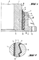
- Figure 1 shows a longitudinal section through a hollow insulator in the area around the Socket.
- the insulating body 1 has one in its center In the longitudinal direction extending, cylindrical cavity 2.
- grit 4 In the field of Socket 3 is applied to the surface of the insulating body 1 grit 4, which can be sintered with a glaze and possibly also an additional layer 5 can have bituminous paint material.
- the armature 6 shows a sawtooth-like profile on the side facing socket 3 and is covered with a layer composite 7 from two layers 8 and 9.
- the Corrosion protection layer 8 is one of the movement between armature 6 and kit shell 10 enabling and catching lubricious layer 9 overlaid.
- the gap between the insulating body 1 and armature 6 is mainly with set or hardened putty material that forms the kit shell 10, filled out.
- the slippery layer 9 occurs after and for a limited time a load a relative movement between the valve and the kit bowl takes place: When loaded, approximately in the direction of the arrow, then in approximately opposite direction.
- the insulating body end face 11 is approximately parallel to the valve face 12.
- Figure 2 shows the detail II of Figure 1 enlarged.
- a so-called medium-sized earth insulator was used for the tests selected, which is common and for operation as a hollow insulator at 145 kV is provided.
- the insulating bodies of the test specimens were made of alumina porcelain.
- the cylindrical trunk ends had one in the area of the socket Outside diameter of approximately 200 mm.
- the fittings consisted of the aluminum alloy G-AlSi10Mg wa and had an internal sawtooth profile.
- the Fittings were covered over the entire inside with the in Table 1 specified materials coated. The coatings were applied by spraying. Other parameters influencing the cementation were kept constant.
- the structure of the layers and the results of the tests are listed in Tables 1 and 2.
- the layer thicknesses were measured eight times over the valve circumference and are approximate values for the slightly fluctuating layer thickness. Structure of the layers. The layer thicknesses are averages over several tests. The layer thickness of the assembly spray was not determined.
- the break test was carried out in the same orientation of the insulator to the test apparatus as in the fourth loading of the bending test. The load was applied until the hollow insulators broke by bending. In each experiment, the three insulators were broken at the top and bottom. Here, 8 strain gauges were attached perpendicular to the longitudinal direction of the insulator on the outwardly projecting edge of the fitting of each fitting in order to determine the fitting expansions. The values of the bending moments were averaged from 6 measured values in each case. Results of the experiments.
- the measured values for the valve expansion which are used in the wrapping tests according to EN 50062 measured at a nominal bending moment of 20 kNm, confirm as it is known analogously from shrink connections that high Radial stresses allow high bending moments.
- the measured high Strain values are based on a relative movement between the kit shell and Fitting, in which the fitting essentially in the longitudinal direction of the isolator Kit case is pulled away from the insulating body; here the fitting is sawtooth-like profile of the fitting and the kit bowl expanded in diameter.
- the moveable layer is crucial for the high valve expansion Load on the putty. This results in a high on the kit bowl effective radial stress with the consequence of high break values. Farther is released when the kit tray is relieved at the end of each mechanical test controlled slide back of the valve and thus a low permanent Valve shift reached.
Landscapes
- Insulators (AREA)
- Insulating Bodies (AREA)
- Organic Low-Molecular-Weight Compounds And Preparation Thereof (AREA)
- Manufacture Of Motors, Generators (AREA)
- Building Environments (AREA)
- Ceramic Products (AREA)
- Coupling Device And Connection With Printed Circuit (AREA)
Claims (13)
- Isolateur électrique avec au moins une pièce de liaison (6) scellée sur un corps isolant (1), dans lequel le corps isolant (1) est lié à la pièce de liaison (6) par l'intermédiaire d'une fi-ette de scellement (10), caractérisé par le fait qu'un complexe de couches (7) est appliquée sur la pièce de liaison (6), entre la frette de scellement (10) et la pièce de liaison (6), lequel complexe de couches comprend au moins deux couches (8, 9) de matériaux différents, par le fait qu'au moins une des couches protège la pièce de liaison contre la corrosion et qu'au moins une couche supplémentaire permet un déplacement entre la frette de scellement (10) et la pièce de liaison (6).
- Isolateur électrique selon la revendication 1, caractérisé par le fait que la couche (8) dotée d'une fonction de protection contre la corrosion présente une épaisseur comprise dans une plage allant de 5 à 1000 µm, de préférence dans une plage allant de 20 à 500 µm et plus particulièrement dans une plage allant de 80 à 200 µm.
- Isolateur électrique selon la revendication 1 ou 2, caractérisé par le fait que la couche (9) permettant un déplacement entre l'enveloppe de scellement et la pièce de liaison présente une épaisseur comprise dans une plage allant de 2 à 1000 µm, de préférence dans une plage allant de 5 à 200 µm et plus particulièrement dans une plage allant de 10 à 80 µm.
- Isolateur électrique selon une des revendications 1 à 3, caractérisé par le fait que deux, trois ou quatre couches de matériaux différents sont appliquées sur la pièce de liaison (6).
- Isolateur électrique selon une des revendications 1 à 4, caractérisé par le fait qu'une couche parmi au moins trois couches est une couche d'agent d'accrochage appliquée sur la pièce de liaison (6).
- Isolateur électrique selon une des revendications 1 à 5, caractérisé par le fait qu'une couche de gravillons (4) est appliquée sur le corps isolant (1) dans la région d'une partie montage (3), couche sur laquelle est appliquée de préférence une couche (5) d'un produit d'enduction bitumeux.
- Isolateur électrique selon une des revendications 1 à 6, caractérisé par le fait que la couche (8) dotée d'une fonction de protection contre la corrosion est une résine coulable ou un vernis réactif ou à base de résines synthétiques, notamment une résine époxyde.
- Isolateur électrique selon une des revendications 1 à 7, caractérisé par le fait que la couche (9) qui permet le déplacement entre la frette de scellement (10) et la pièce de liaison (6) est un produit d'enduction permettant le glissement ou un produit lubrifiant.
- Isolateur électrique selon la revendication 8, caractérisé par le fait que le produit d'enduction permettant le glissement ou le produit lubrifiant est un produit d'enduction à base de bitume, un lubrifiant à base de bisulfure de molybdène ou de graphite, un vernis anti-friction, un lubrifiant à base de métaux, de la graisse ou de l'huile.
- Procédé de fabrication d'un isolateur électrique avec au moins une pièce de liaison (6) scellée sur un corps isolant (1), dans lequel le corps isolant (1) est lié à la pièce de liaison (6) par l'intermédiaire d'une frette de scellement (10), caractérisé par le fait que l'on revêt la face intérieure de la pièce de liaison (6) tournée vers la frette de scellement (10) d'au moins une couche (8) dotée d'une fonction de protection contre la corrosion et d'une couche (9) permettant le déplacement entre la frette de scellement et la pièce de liaison.
- Procédé de fabrication d'un isolateur électrique selon la revendication 10, caractérisé par le fait que le matériau pour la couche (8) dotée d'une fonction de protection contre la corrosion est appliqué par badigeonnage ou par pulvérisation sur la pièce de liaison (6) ou sur une couche d'accrochage appliquée sur la pièce de liaison (6).
- Procédé de fabrication d'un isolateur électrique selon la revendication 10, caractérisé par le fait que la couche (9) permettant le déplacement entre la frette de scellement (10) et la pièce de liaison (6) est appliqué par badigeonnage ou par pulvérisation sur la pièce de liaison (6).
- Procédé de fabrication d'un isolateur électrique selon une des revendications 10 à 12, caractérisé par le fait que comme matériau de scellement on coule un mortier coulable dans l'interstice entre le corps isolant (1) et la pièce de liaison (6) enduite, lequel mortier durcit dans l'inters tice.
Applications Claiming Priority (3)
| Application Number | Priority Date | Filing Date | Title |
|---|---|---|---|
| DE19503324A DE19503324A1 (de) | 1995-02-02 | 1995-02-02 | Isolator mit Kittverbindung und Verfahren zu seiner Herstellung |
| DE19503324 | 1995-02-02 | ||
| PCT/EP1996/000226 WO1996024144A1 (fr) | 1995-02-02 | 1996-01-19 | Isolateur fixe par ciment et son procede de production |
Publications (2)
| Publication Number | Publication Date |
|---|---|
| EP0807310A1 EP0807310A1 (fr) | 1997-11-19 |
| EP0807310B1 true EP0807310B1 (fr) | 1998-10-14 |
Family
ID=7752969
Family Applications (1)
| Application Number | Title | Priority Date | Filing Date |
|---|---|---|---|
| EP96901742A Revoked EP0807310B1 (fr) | 1995-02-02 | 1996-01-19 | Isolateur fixe par ciment et son procede de production |
Country Status (15)
| Country | Link |
|---|---|
| US (1) | US5985087A (fr) |
| EP (1) | EP0807310B1 (fr) |
| JP (1) | JPH10513004A (fr) |
| CN (1) | CN1089936C (fr) |
| AT (1) | ATE172321T1 (fr) |
| BR (1) | BR9607580A (fr) |
| CA (1) | CA2212255C (fr) |
| CZ (1) | CZ289279B6 (fr) |
| DE (2) | DE19503324A1 (fr) |
| ES (1) | ES2122783T3 (fr) |
| FI (1) | FI960446A7 (fr) |
| IL (1) | IL116979A (fr) |
| PL (1) | PL178732B1 (fr) |
| WO (1) | WO1996024144A1 (fr) |
| ZA (1) | ZA96775B (fr) |
Families Citing this family (5)
| Publication number | Priority date | Publication date | Assignee | Title |
|---|---|---|---|---|
| FR2765385B1 (fr) * | 1997-06-26 | 2003-12-05 | Gec Alsthom T & D Sa | Ferrure d'isolateur composite |
| IT1299049B1 (it) * | 1998-04-08 | 2000-02-07 | Abb Research Ltd | Isolatore particolarmente per linee elettriche di trasmissione e distribuzione, avente caratteristiche migliorate di resistenza alle |
| DE10213111A1 (de) * | 2002-03-23 | 2003-10-02 | Tesa Ag | Mehrschichtige Laser-Transferfolie zum dauerhaften Beschriften von Bauteilen |
| ATE521070T1 (de) * | 2007-05-23 | 2011-09-15 | Abb Technology Ag | Hochspannungsisolator und kühlelement mit diesem hochspannungsisolator |
| US10584475B1 (en) * | 2019-06-19 | 2020-03-10 | Soleman Abdi Idd | Method and system for construction and building |
Family Cites Families (9)
| Publication number | Priority date | Publication date | Assignee | Title |
|---|---|---|---|---|
| US3576938A (en) * | 1969-11-07 | 1971-05-04 | Gen Electric | Electrical insulator with polymer-containing joint between the porcelain and the hardware |
| FR2292318A1 (fr) * | 1974-11-25 | 1976-06-18 | Ceraver | Perfectionnement a la liaison entre ame et armatures de structures comportant une ame de fibres agglomerees |
| US4267402A (en) * | 1978-08-07 | 1981-05-12 | Gould Inc. | Polymer concrete body with vibration molded threads, method of making same, and electrical insulator provided with the same |
| FR2445596A2 (fr) * | 1978-12-27 | 1980-07-25 | Ceraver | Perfectionnement a la liaison entre ame et armatures de structures comportant une ame de fibres agglomerees |
| FR2499301A1 (fr) * | 1981-02-05 | 1982-08-06 | Ceraver | Isolateur en matiere organique comportant une ame en stratifie |
| DE4212146C1 (en) * | 1992-04-10 | 1993-08-19 | Siemens Ag, 8000 Muenchen, De | Light conductor with optical fibres inside three consecutive layers - has its fibres loosely embedded in filling paste, then inside second polymer with higher thermal stability and outermost extruded sleeve |
| FR2702081B1 (fr) * | 1993-02-26 | 1995-05-12 | Gec Alsthom T & D Sa | Isolateur. |
| EP0615259B1 (fr) * | 1993-03-12 | 1996-05-15 | GEC Alsthom T&D AG | Procédé de fabrication d'une liaison en mastic entre un isolateur et une armature et ensemble isolateur |
| CN1089477C (zh) * | 1994-03-28 | 2002-08-21 | 日本碍子株式会社 | 具有导电表面涂层以防止电晕放电的绝缘子 |
-
1995
- 1995-02-02 DE DE19503324A patent/DE19503324A1/de not_active Ceased
-
1996
- 1996-01-19 JP JP8523204A patent/JPH10513004A/ja not_active Ceased
- 1996-01-19 AT AT96901742T patent/ATE172321T1/de not_active IP Right Cessation
- 1996-01-19 ES ES96901742T patent/ES2122783T3/es not_active Expired - Lifetime
- 1996-01-19 BR BR9607580A patent/BR9607580A/pt active Search and Examination
- 1996-01-19 EP EP96901742A patent/EP0807310B1/fr not_active Revoked
- 1996-01-19 PL PL96321681A patent/PL178732B1/pl not_active IP Right Cessation
- 1996-01-19 CA CA002212255A patent/CA2212255C/fr not_active Expired - Fee Related
- 1996-01-19 CN CN96191727A patent/CN1089936C/zh not_active Expired - Fee Related
- 1996-01-19 WO PCT/EP1996/000226 patent/WO1996024144A1/fr not_active Ceased
- 1996-01-19 DE DE59600669T patent/DE59600669D1/de not_active Expired - Fee Related
- 1996-01-19 CZ CZ19972420A patent/CZ289279B6/cs not_active IP Right Cessation
- 1996-01-19 US US08/875,691 patent/US5985087A/en not_active Expired - Fee Related
- 1996-01-31 IL IL11697996A patent/IL116979A/xx not_active IP Right Cessation
- 1996-01-31 FI FI960446A patent/FI960446A7/fi not_active IP Right Cessation
- 1996-02-01 ZA ZA96775A patent/ZA96775B/xx unknown
Also Published As
| Publication number | Publication date |
|---|---|
| FI960446L (fi) | 1996-08-03 |
| ZA96775B (en) | 1996-08-12 |
| ATE172321T1 (de) | 1998-10-15 |
| FI960446A7 (fi) | 1996-08-03 |
| CA2212255C (fr) | 2004-10-26 |
| CN1089936C (zh) | 2002-08-28 |
| CN1172546A (zh) | 1998-02-04 |
| WO1996024144A1 (fr) | 1996-08-08 |
| CZ289279B6 (cs) | 2001-12-12 |
| CA2212255A1 (fr) | 1996-08-08 |
| JPH10513004A (ja) | 1998-12-08 |
| PL321681A1 (en) | 1997-12-22 |
| DE19503324A1 (de) | 1996-08-08 |
| IL116979A0 (en) | 1996-05-14 |
| FI960446A0 (fi) | 1996-01-31 |
| US5985087A (en) | 1999-11-16 |
| DE59600669D1 (de) | 1998-11-19 |
| BR9607580A (pt) | 1998-07-07 |
| EP0807310A1 (fr) | 1997-11-19 |
| PL178732B1 (pl) | 2000-06-30 |
| ES2122783T3 (es) | 1998-12-16 |
| CZ242097A3 (en) | 1997-11-12 |
| IL116979A (en) | 2000-07-16 |
Similar Documents
| Publication | Publication Date | Title |
|---|---|---|
| DE3228386C2 (fr) | ||
| EP2729621B1 (fr) | Système destiné à supporter un organe de traction, notamment un hauban, dans un sens perpendiculaire à son étendue longitudinale | |
| DE68923145T2 (de) | Verbundisolator mit optischer Faser und Verfahren zu dessen Herstellung. | |
| DE3034579A1 (de) | Hochspannungs-freiluft-kunststoffisolator und verfahren zu seiner herstellung | |
| EP0688025B1 (fr) | Isolateur haute tension en céramique | |
| DE1926097A1 (de) | Kondensator-Durchfuehrung mit Giessharzisolator und Vorrichtung zur Herstellung einer solchen Durchfuehrung | |
| EP0807310B1 (fr) | Isolateur fixe par ciment et son procede de production | |
| EP1882496A1 (fr) | Pare-feu | |
| EP1027478A1 (fr) | Procede permettant d'augmenter la resistance a la corrosion du beton arme | |
| DE3429251C2 (de) | Wärmedämmung für Bauwerkswände | |
| EP1505218B1 (fr) | Système composite d'isolation thermique | |
| DE1615545A1 (de) | Stromschienentraeger | |
| DE69203282T2 (de) | Zugangskabel für einen Unterwasserverstärker. | |
| DE102010061539A1 (de) | Wärmedämmverbundsystem sowie Fassadendämmplatte hierfür und Verfahren zur Herstellung der Fassadendämmplatte | |
| DE102020117497A1 (de) | Schutzummantelung für pfahlartige Bauelemente | |
| DE102006058668A1 (de) | Ankerstange, Verfahren zur Herstellung einer Ankerstange und Windkraftanlage | |
| EP0663492A1 (fr) | Elément de construction avec une plaque en béton et au moins une plaque en pierre fixée sur celle-ci | |
| DE10009474C1 (de) | Schichtdielektrikum | |
| DE657749C (de) | Verfahren zum Anbringen unverschieblicher Anschluesse an gespannten Kabeln | |
| DE19940455C2 (de) | Zündeinrichtung,insbesondere Zündkerze für Ottomotoren, und Verfahren zur Lackierung derselben | |
| DE4209661A1 (de) | Verfahren und Einrichtung zur Erkennung von unplanmäßig auftretenden Rissen in Stahlbetonbauwerken | |
| DE4343745C2 (de) | Vorrichtung mit Sonden für die zerstörungsfreie Prüfung von Werkstücken und Verfahren zur Herstellung der Vorrichtung | |
| DE29706972U1 (de) | Vorrichtung zum Einleiten von Kräften in weniger feste oder artfremde Materialien | |
| DE964153C (de) | Aus mehreren Teilen zusammengesetzter Mast fuer Hochspannungsleitungen, der eine elektrisch isolierende oder schlechtleitende Stossverbindung aufweist | |
| EP1002912B1 (fr) | Méthode pour réaliser un contact éléctrique entre armatures à béton |
Legal Events
| Date | Code | Title | Description |
|---|---|---|---|
| PUAI | Public reference made under article 153(3) epc to a published international application that has entered the european phase |
Free format text: ORIGINAL CODE: 0009012 |
|
| 17P | Request for examination filed |
Effective date: 19970902 |
|
| AK | Designated contracting states |
Kind code of ref document: A1 Designated state(s): AT BE CH DE ES FR GB IT LI PT SE |
|
| GRAG | Despatch of communication of intention to grant |
Free format text: ORIGINAL CODE: EPIDOS AGRA |
|
| 17Q | First examination report despatched |
Effective date: 19971218 |
|
| GRAG | Despatch of communication of intention to grant |
Free format text: ORIGINAL CODE: EPIDOS AGRA |
|
| GRAG | Despatch of communication of intention to grant |
Free format text: ORIGINAL CODE: EPIDOS AGRA |
|
| GRAH | Despatch of communication of intention to grant a patent |
Free format text: ORIGINAL CODE: EPIDOS IGRA |
|
| GRAH | Despatch of communication of intention to grant a patent |
Free format text: ORIGINAL CODE: EPIDOS IGRA |
|
| GRAA | (expected) grant |
Free format text: ORIGINAL CODE: 0009210 |
|
| AK | Designated contracting states |
Kind code of ref document: B1 Designated state(s): AT BE CH DE ES FR GB IT LI PT SE |
|
| REF | Corresponds to: |
Ref document number: 172321 Country of ref document: AT Date of ref document: 19981015 Kind code of ref document: T |
|
| REG | Reference to a national code |
Ref country code: CH Ref legal event code: EP |
|
| REF | Corresponds to: |
Ref document number: 59600669 Country of ref document: DE Date of ref document: 19981119 |
|
| REG | Reference to a national code |
Ref country code: CH Ref legal event code: NV Representative=s name: ISLER & PEDRAZZINI AG |
|
| REG | Reference to a national code |
Ref country code: ES Ref legal event code: FG2A Ref document number: 2122783 Country of ref document: ES Kind code of ref document: T3 |
|
| ET | Fr: translation filed | ||
| GBT | Gb: translation of ep patent filed (gb section 77(6)(a)/1977) |
Effective date: 19981224 |
|
| REG | Reference to a national code |
Ref country code: PT Ref legal event code: SC4A Free format text: AVAILABILITY OF NATIONAL TRANSLATION Effective date: 19981126 |
|
| PLBI | Opposition filed |
Free format text: ORIGINAL CODE: 0009260 |
|
| PLBF | Reply of patent proprietor to notice(s) of opposition |
Free format text: ORIGINAL CODE: EPIDOS OBSO |
|
| 26 | Opposition filed |
Opponent name: SIEMENS AG Effective date: 19990714 |
|
| PLBF | Reply of patent proprietor to notice(s) of opposition |
Free format text: ORIGINAL CODE: EPIDOS OBSO |
|
| REG | Reference to a national code |
Ref country code: GB Ref legal event code: IF02 |
|
| PLBQ | Unpublished change to opponent data |
Free format text: ORIGINAL CODE: EPIDOS OPPO |
|
| PLAB | Opposition data, opponent's data or that of the opponent's representative modified |
Free format text: ORIGINAL CODE: 0009299OPPO |
|
| R26 | Opposition filed (corrected) |
Opponent name: SIEMENS AG Effective date: 19990714 |
|
| PGFP | Annual fee paid to national office [announced via postgrant information from national office to epo] |
Ref country code: PT Payment date: 20031223 Year of fee payment: 9 |
|
| PGFP | Annual fee paid to national office [announced via postgrant information from national office to epo] |
Ref country code: GB Payment date: 20040105 Year of fee payment: 9 |
|
| PGFP | Annual fee paid to national office [announced via postgrant information from national office to epo] |
Ref country code: CH Payment date: 20040106 Year of fee payment: 9 |
|
| PGFP | Annual fee paid to national office [announced via postgrant information from national office to epo] |
Ref country code: FR Payment date: 20040109 Year of fee payment: 9 |
|
| PGFP | Annual fee paid to national office [announced via postgrant information from national office to epo] |
Ref country code: ES Payment date: 20040122 Year of fee payment: 9 |
|
| REG | Reference to a national code |
Ref country code: CH Ref legal event code: PUE Owner name: LAPP INSULATOR GMBH & CO. KG Free format text: CERAMTEC AG INNOVATIVE CERAMIC ENGINEERING#FABRIKSTRASSE 23 - 29#73207 PLOCHINGEN (DE) -TRANSFER TO- LAPP INSULATOR GMBH & CO. KG#BAHNHOFSTRASSE 5#95632 WUNSIEDEL (DE) |
|
| REG | Reference to a national code |
Ref country code: GB Ref legal event code: 732E |
|
| REG | Reference to a national code |
Ref country code: FR Ref legal event code: TP |
|
| PG25 | Lapsed in a contracting state [announced via postgrant information from national office to epo] |
Ref country code: IT Free format text: LAPSE BECAUSE OF NON-PAYMENT OF DUE FEES;WARNING: LAPSES OF ITALIAN PATENTS WITH EFFECTIVE DATE BEFORE 2007 MAY HAVE OCCURRED AT ANY TIME BEFORE 2007. THE CORRECT EFFECTIVE DATE MAY BE DIFFERENT FROM THE ONE RECORDED. Effective date: 20050119 Ref country code: GB Free format text: LAPSE BECAUSE OF NON-PAYMENT OF DUE FEES Effective date: 20050119 |
|
| PG25 | Lapsed in a contracting state [announced via postgrant information from national office to epo] |
Ref country code: ES Free format text: LAPSE BECAUSE OF NON-PAYMENT OF DUE FEES Effective date: 20050120 |
|
| PG25 | Lapsed in a contracting state [announced via postgrant information from national office to epo] |
Ref country code: LI Free format text: LAPSE BECAUSE OF NON-PAYMENT OF DUE FEES Effective date: 20050131 Ref country code: CH Free format text: LAPSE BECAUSE OF NON-PAYMENT OF DUE FEES Effective date: 20050131 |
|
| REG | Reference to a national code |
Ref country code: ES Ref legal event code: PC2A |
|
| PGFP | Annual fee paid to national office [announced via postgrant information from national office to epo] |
Ref country code: DE Payment date: 20050330 Year of fee payment: 10 |
|
| PLAB | Opposition data, opponent's data or that of the opponent's representative modified |
Free format text: ORIGINAL CODE: 0009299OPPO |
|
| PLAQ | Examination of admissibility of opposition: information related to despatch of communication + time limit deleted |
Free format text: ORIGINAL CODE: EPIDOSDOPE2 |
|
| PLAR | Examination of admissibility of opposition: information related to receipt of reply deleted |
Free format text: ORIGINAL CODE: EPIDOSDOPE4 |
|
| PLBQ | Unpublished change to opponent data |
Free format text: ORIGINAL CODE: EPIDOS OPPO |
|
| PG25 | Lapsed in a contracting state [announced via postgrant information from national office to epo] |
Ref country code: PT Free format text: LAPSE BECAUSE OF NON-PAYMENT OF DUE FEES Effective date: 20050719 |
|
| R26 | Opposition filed (corrected) |
Opponent name: ARGILLON GMBH Effective date: 19990714 |
|
| GBPC | Gb: european patent ceased through non-payment of renewal fee |
Effective date: 20050119 |
|
| REG | Reference to a national code |
Ref country code: CH Ref legal event code: PL |
|
| PG25 | Lapsed in a contracting state [announced via postgrant information from national office to epo] |
Ref country code: FR Free format text: LAPSE BECAUSE OF NON-PAYMENT OF DUE FEES Effective date: 20050930 |
|
| REG | Reference to a national code |
Ref country code: PT Ref legal event code: MM4A Effective date: 20050719 |
|
| REG | Reference to a national code |
Ref country code: FR Ref legal event code: ST |
|
| PGFP | Annual fee paid to national office [announced via postgrant information from national office to epo] |
Ref country code: SE Payment date: 20060112 Year of fee payment: 11 |
|
| PGFP | Annual fee paid to national office [announced via postgrant information from national office to epo] |
Ref country code: AT Payment date: 20060113 Year of fee payment: 11 |
|
| RDAF | Communication despatched that patent is revoked |
Free format text: ORIGINAL CODE: EPIDOSNREV1 |
|
| PGFP | Annual fee paid to national office [announced via postgrant information from national office to epo] |
Ref country code: BE Payment date: 20060207 Year of fee payment: 11 |
|
| REG | Reference to a national code |
Ref country code: ES Ref legal event code: FD2A Effective date: 20050120 |
|
| RDAG | Patent revoked |
Free format text: ORIGINAL CODE: 0009271 |
|
| STAA | Information on the status of an ep patent application or granted ep patent |
Free format text: STATUS: PATENT REVOKED |
|
| 27W | Patent revoked |
Effective date: 20060209 |
|
| REG | Reference to a national code |
Ref country code: SE Ref legal event code: ECNC |