EP0807235B1 - Method and device for drying out buildings and/or fixed components - Google Patents
Method and device for drying out buildings and/or fixed components Download PDFInfo
- Publication number
- EP0807235B1 EP0807235B1 EP96945890A EP96945890A EP0807235B1 EP 0807235 B1 EP0807235 B1 EP 0807235B1 EP 96945890 A EP96945890 A EP 96945890A EP 96945890 A EP96945890 A EP 96945890A EP 0807235 B1 EP0807235 B1 EP 0807235B1
- Authority
- EP
- European Patent Office
- Prior art keywords
- radiation
- drying
- building
- magnetrons
- buildings
- Prior art date
- Legal status (The legal status is an assumption and is not a legal conclusion. Google has not performed a legal analysis and makes no representation as to the accuracy of the status listed.)
- Expired - Lifetime
Links
- 238000001035 drying Methods 0.000 title claims abstract description 74
- 238000000034 method Methods 0.000 title claims description 21
- 230000005855 radiation Effects 0.000 claims abstract description 32
- 239000004566 building material Substances 0.000 claims abstract description 9
- 230000010355 oscillation Effects 0.000 claims abstract 2
- 239000000463 material Substances 0.000 claims description 11
- 239000002184 metal Substances 0.000 claims description 7
- 230000002787 reinforcement Effects 0.000 claims description 4
- 238000005096 rolling process Methods 0.000 claims description 3
- 239000011888 foil Substances 0.000 claims description 2
- 150000001875 compounds Chemical class 0.000 claims 1
- 238000010276 construction Methods 0.000 abstract description 11
- 238000010438 heat treatment Methods 0.000 description 10
- 230000000694 effects Effects 0.000 description 6
- 230000008569 process Effects 0.000 description 6
- 239000000126 substance Substances 0.000 description 6
- 238000001816 cooling Methods 0.000 description 5
- 238000001228 spectrum Methods 0.000 description 5
- XLYOFNOQVPJJNP-UHFFFAOYSA-N water Substances O XLYOFNOQVPJJNP-UHFFFAOYSA-N 0.000 description 4
- 230000006378 damage Effects 0.000 description 3
- 238000009792 diffusion process Methods 0.000 description 3
- 238000009413 insulation Methods 0.000 description 3
- 239000000523 sample Substances 0.000 description 3
- 241000607479 Yersinia pestis Species 0.000 description 2
- 230000005540 biological transmission Effects 0.000 description 2
- 239000002131 composite material Substances 0.000 description 2
- 230000007547 defect Effects 0.000 description 2
- 230000018044 dehydration Effects 0.000 description 2
- 238000006297 dehydration reaction Methods 0.000 description 2
- 238000009826 distribution Methods 0.000 description 2
- 230000005284 excitation Effects 0.000 description 2
- 230000033001 locomotion Effects 0.000 description 2
- 238000009417 prefabrication Methods 0.000 description 2
- 230000008929 regeneration Effects 0.000 description 2
- 238000011069 regeneration method Methods 0.000 description 2
- 238000001179 sorption measurement Methods 0.000 description 2
- 229910000831 Steel Inorganic materials 0.000 description 1
- 230000001133 acceleration Effects 0.000 description 1
- 230000004308 accommodation Effects 0.000 description 1
- 230000009471 action Effects 0.000 description 1
- 230000006978 adaptation Effects 0.000 description 1
- 239000010426 asphalt Substances 0.000 description 1
- 230000004888 barrier function Effects 0.000 description 1
- 230000008901 benefit Effects 0.000 description 1
- 238000007664 blowing Methods 0.000 description 1
- 239000013590 bulk material Substances 0.000 description 1
- 239000000919 ceramic Substances 0.000 description 1
- 230000008859 change Effects 0.000 description 1
- 238000009833 condensation Methods 0.000 description 1
- 230000005494 condensation Effects 0.000 description 1
- 239000000109 continuous material Substances 0.000 description 1
- 238000007796 conventional method Methods 0.000 description 1
- 230000008878 coupling Effects 0.000 description 1
- 238000010168 coupling process Methods 0.000 description 1
- 238000005859 coupling reaction Methods 0.000 description 1
- 230000007812 deficiency Effects 0.000 description 1
- 238000007791 dehumidification Methods 0.000 description 1
- 230000001934 delay Effects 0.000 description 1
- 230000003111 delayed effect Effects 0.000 description 1
- 230000001419 dependent effect Effects 0.000 description 1
- 238000013461 design Methods 0.000 description 1
- 238000011161 development Methods 0.000 description 1
- 230000018109 developmental process Effects 0.000 description 1
- 238000005553 drilling Methods 0.000 description 1
- 230000005611 electricity Effects 0.000 description 1
- 230000005670 electromagnetic radiation Effects 0.000 description 1
- 230000008030 elimination Effects 0.000 description 1
- 238000003379 elimination reaction Methods 0.000 description 1
- 238000005265 energy consumption Methods 0.000 description 1
- 230000007613 environmental effect Effects 0.000 description 1
- 239000004744 fabric Substances 0.000 description 1
- 239000008187 granular material Substances 0.000 description 1
- 238000007602 hot air drying Methods 0.000 description 1
- 230000002401 inhibitory effect Effects 0.000 description 1
- 239000011810 insulating material Substances 0.000 description 1
- 239000007788 liquid Substances 0.000 description 1
- 239000011344 liquid material Substances 0.000 description 1
- 238000004519 manufacturing process Methods 0.000 description 1
- 230000005012 migration Effects 0.000 description 1
- 238000013508 migration Methods 0.000 description 1
- 239000011490 mineral wool Substances 0.000 description 1
- 238000000465 moulding Methods 0.000 description 1
- 239000000123 paper Substances 0.000 description 1
- 230000035515 penetration Effects 0.000 description 1
- 239000011505 plaster Substances 0.000 description 1
- 239000004033 plastic Substances 0.000 description 1
- 229920003023 plastic Polymers 0.000 description 1
- 238000003825 pressing Methods 0.000 description 1
- 239000007787 solid Substances 0.000 description 1
- 239000007858 starting material Substances 0.000 description 1
- 239000010959 steel Substances 0.000 description 1
- 238000003860 storage Methods 0.000 description 1
- 230000001360 synchronised effect Effects 0.000 description 1
- 230000002123 temporal effect Effects 0.000 description 1
- 239000004753 textile Substances 0.000 description 1
- 238000012546 transfer Methods 0.000 description 1
- 238000011144 upstream manufacturing Methods 0.000 description 1
- 238000010792 warming Methods 0.000 description 1
- 239000002023 wood Substances 0.000 description 1
Images


Classifications
-
- F—MECHANICAL ENGINEERING; LIGHTING; HEATING; WEAPONS; BLASTING
- F26—DRYING
- F26B—DRYING SOLID MATERIALS OR OBJECTS BY REMOVING LIQUID THEREFROM
- F26B3/00—Drying solid materials or objects by processes involving the application of heat
- F26B3/32—Drying solid materials or objects by processes involving the application of heat by development of heat within the materials or objects to be dried, e.g. by fermentation or other microbiological action
- F26B3/34—Drying solid materials or objects by processes involving the application of heat by development of heat within the materials or objects to be dried, e.g. by fermentation or other microbiological action by using electrical effects
- F26B3/347—Electromagnetic heating, e.g. induction heating or heating using microwave energy
-
- E—FIXED CONSTRUCTIONS
- E04—BUILDING
- E04B—GENERAL BUILDING CONSTRUCTIONS; WALLS, e.g. PARTITIONS; ROOFS; FLOORS; CEILINGS; INSULATION OR OTHER PROTECTION OF BUILDINGS
- E04B1/00—Constructions in general; Structures which are not restricted either to walls, e.g. partitions, or floors or ceilings or roofs
- E04B1/62—Insulation or other protection; Elements or use of specified material therefor
- E04B1/70—Drying or keeping dry, e.g. by air vents
- E04B1/7007—Drying or keeping dry, e.g. by air vents by using electricity, e.g. electro-osmosis
Definitions
- the invention relates to the technical field of drying Buildings and / or fixed components by removing construction related moisture that has arisen or penetrated by external influences Help high-frequency energy radiation and starts from a device According to the preamble of claim 1, or of a method according to the preamble of claim 3.
- a device According to the preamble of claim 1, or of a method according to the preamble of claim 3.
- Such a device and such a method are already known from DE-U-9 413 736.
- DE 33 06 044 describes a technical solution according to which dry air is pressed into a building gap and moist air is drawn off at another point in this building gap.
- DE 38 15 161 describes an almost identical solution to drying by pressing in dry air and suctioning off moist air between layers, whereby in particular insulating materials are to be dried under screed layers.
- DE 40 21 710 describes a device which likewise, but here as an endless dryer, dries a material located on a conveyor belt with heaters and blown hot gas. During adsorption drying, the moisture is accumulated hygroscopically or capillary. The hygroscopic material is used up and is regenerated or disposed of.
- Capillary systems can be used as often as required after regeneration and can hardly be used with temperature or humidity restrictions.
- the state of the art of such a type of drying is described, among other things, in DE 40 09 691.
- the air is forced through an adsorbing or absorbing dry material, the air is conveyed to a less moist or completely dry state and then closed in due time the regeneration of the dry material by heat. Since both types of drying work via the climatic conditions on the surface of the components, i.e. via external conditions relative to the components, they often have to be influenced by additional measures and equipment, whereby to support and enhance the drying effect, blowers that flank the moisture out of the Transport the component and / or the building or use it to blow hot air.
- the moisture front better the peak of the moisture distribution within the component to be dried, is displaced into the interior of the component. If the moisture / moisture distribution shifted in this way cannot escape through the outer sides due to unfavorable building physics and / or structural conditions, the drying process is considerably delayed or even impossible. Due to the warming of the inner layer, in unfavorable constellations, there may even be an increase in moisture after the drying work has been completed. If there are diffusion-inhibiting wall coverings and / or wall structures, for example if full thermal insulation is applied, almost no moisture is released from the facade. In the case of hollow-hole masonry, the wall is preferably drilled and hot air is blown out.
- Such solutions are represented by DE 32 03 132 - heating a liquid material in a container - and DE 40 09 691 - heating and drying an adsorbing or absorbing drying material in a container or drying room.
- the document DE 91 15 185 also belongs to this group of cases if it also represents a partially closed space - tube arrangement with screw conveyor - and transport goods moving through it - starting materials for ceramic masses, consequently loose, lumpy or powdery material.
- a similar device is shown in DE 39 07 248, which dries asphalt granulate by passing through a microwave field with a trough body with a dome and tubular inlets and outlets and a screw conveyor.
- the technical solution according to DE 33 32 437 also works according to the principle of microwave irradiation of a stored product in a vacuum dry container, which alone results in a restriction to relatively small spatial sizes of the vacuum container as well as the dry goods.
- the above-mentioned container solutions are only suitable for the treatment of loose, movable goods of small dimensions, but in no way for the drying of built-up parts of buildings.
- the accommodation of larger objects within the effective range of high-energy radiation simply fails at the limit of the effort-performance ratio.
- a second case group of the known microwave dryers are the stationary arrangements as partially open or open systems, which are equipped with conveyors on which the material to be dried is passed through a microwave field and is heated or dried in this way.
- DE-U-94 13 736 discloses a microwave drying and pest control system. From the functional description 1.2.1.1 and 1.2.2.1 as well as from the principle description 1.2.2 parts of the arrangement and process description can be seen. This technical solution works with radiation heads or with radiation probes, in which high-frequency alternating fields are generated by means of high-frequency magnetrons (shown under 1.2.1.1), and with further arrangement components and large-area reflectors (1.2.2, 2nd line and Figure 2).
- the radiation heads or radiation probes shown in accordance with the arrangement must always be in contact with the building substance to be dried, see all figures shown above, which has proven to be the main deficiency of this technical solution.
- High-frequency heating and thus drying or, for example, pest destruction is only possible at the points where the radiation heads or radiation probes can reach or be applied, which means that this technical solution also forms a "closed" system with its objects to be dried must not be able to work from a distance, making certain corners, angles, niches or undercuts impossible to reach.
- the comprehensive description of the known prior art shows that the problem of drying structural parts or structures with all its defects still exists and that no satisfactory solution has yet been able to be found by experts.
- the invention is based on the object a method and an arrangement for drying buildings and / or To create stationary components, the acceleration of the liquid outlet at the component interfaces with air with the help of electromagnetic Energy radiation is made possible and the cost of that Shielding radiation emissions in economically justifiable Areas.
- the water to be removed should not be passively involved in the drying process, but rather as an active one Component act by itself as a medium for energy transfer acts, thus contributes to its elimination and thus one Drying of the building part is effected from the inside.
- Task of The invention is also intended to be the drying process on the aforementioned Parts in extremely short times for this technical area, in a dry time area of at most a few hours, regardless of the to design climatic environmental conditions and on complicated building structures, who hardly blow with warm air or hardly any of them Humid air can be extracted to allow.
- Aim of the invention it should be to create an exact predictability of the drying process and thus reliable planning bases for the construction process create.
- the invention is not intended to be presented in a stationary system, but it is to create a mobile arrangement with which too the mobility of the procedure is guaranteed.
- the resonator elements are in the form of a metal-coated film immediately with the manufacture the components of the structure in prefabrication or on the construction site molded into it itself, which then also has a double function take over the previous task of the barrier film, especially in the case of complicated ones Floor constructions.
- Such resonator elements can also be used as gratings - composites, such as metallic rods, bars, grids, nets or the like, in the building parts molded in to remain or enclosed. At their molding also often fulfills the function in parallel component reinforcement / reinforcement. In such a case there will be connections produced by means of coupling points and via waveguides to the magnetron. Such connections are also provided when the magnetron is to be set up outside the building and the energy radiation generated is to be spent inside the building or component. For the drying of building areas that encompass a room become resonators in the form of an antenna arranged centrally in the room.
- a resonator 4 which effects the function of vibrating transmission and excitation, is connected to a magnetron 2, which generates the high-frequency electromagnetic waves, via a waveguide 3 and set up centrally in the room.
- the resonator 4 is rotatably arranged so that the high-frequency energy radiation reaches and penetrates all outer and inner walls 1 including floor 1 and ceiling 1 of the building part, the point of attack of the drying process and its arrangement not, as previously, on the outside of the wall surfaces, but instead is placed inside the component, ie the water vapor diffusion is effected from the inside out.
- the penetration depth is determined by the moisture contained and the material of the respective component.
- This depth can therefore be very different depending on the component, as a result of which the speed of drying out will be different in the various components.
- it can therefore also be expedient to carry out a different temporal limitation continuously combined with impulse-like directed irradiation when a room dries out, or to provide several resonator elements with a different frequency spectrum depending on the respective spatial conditions. If a component, for example an inner wall 1 in front of the other components, for example the much thicker outer walls 1 or ceilings 1, has dried out, this component becomes effective as a waveguide and the microwave radiation penetrates through this component.
- shields 5 in this case also surround the space to be irradiated as radiation reflectors 8 in the form of, for example, metallic gratings or nets.
- This is achieved in accordance with the proposed inventive teaching in this exemplary embodiment by means of a metal grid incorporated into the plaster during construction.
- the energy supply to the drying arrangement which here is more than 25 kW, is realized either by a generator from the outside or by means of electrical safety devices from the interior of the building. The initial energy consumption is reduced by more than 50% with the effort.
- Wet masonry parts 1 are by means of a magnetron 2 with a cooling system 2a and a generator (power supply) 6, all in one Housing located, exposed to high-frequency energy radiation.
- a pulling device 7 the housing with the ones located therein Magnetron 2, cooling system 2a and generator 6 and the reflector 8, which consists of a metal grid, a metal plate or a
- the reflector 8 which consists of a metal grid, a metal plate or a
- a magnet with an upstream plate and opposite the magnetron 2 is positioned at the same speed on the masonry part 1 moved along.
- a magnetron (with cooling system) 2 which is located in a housing, which in turn is designed as a drawing slide 9 with roller wheels 10 and is connected to a generator 6, by means of steel cables 7 on one Building part 1, for example a bridge pillar or a dam, guided from top to bottom at a defined speed. So that will allows drying in hard-to-reach places.
- a slide 9 used for drying a flat roof, large screed or foundation areas or also highway sections 1 will also be an arrangement in shape a slide 9 used.
- This slide 9 serves as Device carrier, which can be extended as required, the Magnetrone 2 with cooling system contains and is connected to the power supply. To carry out the method, this pull slide 9 is on a slideway 11 the surface to be dried moves. Taking advantage of the building fabric 1 incorporated reinforcement 12, which in this case as a reflector and This accelerates the large area in a short amount of time dried.
- Magnetrons 2 which are connected to the power supply 6, arranged. These magnetrons 2 can both all have the same frequency spectrum as well as each working with a different frequency spectrum.
Landscapes
- Engineering & Computer Science (AREA)
- Microbiology (AREA)
- Electromagnetism (AREA)
- Architecture (AREA)
- Life Sciences & Earth Sciences (AREA)
- Physics & Mathematics (AREA)
- Biomedical Technology (AREA)
- Electrochemistry (AREA)
- Molecular Biology (AREA)
- Mechanical Engineering (AREA)
- General Engineering & Computer Science (AREA)
- Chemical & Material Sciences (AREA)
- Chemical Kinetics & Catalysis (AREA)
- Biotechnology (AREA)
- Water Supply & Treatment (AREA)
- Health & Medical Sciences (AREA)
- Civil Engineering (AREA)
- Structural Engineering (AREA)
- Drying Of Solid Materials (AREA)
- Constitution Of High-Frequency Heating (AREA)
Abstract
Description
Die Erfindung bezieht sich auf das technische Gebiet des Trocknens von
Gebäuden und/oder ortsfester Bauteile durch das Entfernen von baubedingt
entstandener oder durch Fremdeinwirkung eingedrungener Feuchtigkeit mit
Hilfe hochfrequenter Energiestrahlung und geht aus von einer Vorrichtung
gemäß dem Oberbegriff des Patentanspruchs 1, bzw. von einem Verfahren gemäß dem Oberbegriff des Patentanspruchs 3. Eine derartige Vorrichtung und ein derartiges Verfahren sind aus dem DE-U-9 413 736 bereits bekannt.The invention relates to the technical field of drying
Buildings and / or fixed components by removing construction related
moisture that has arisen or penetrated by external influences
Help high-frequency energy radiation and starts from a device
According to the preamble of
Zum Trocknen von feuchten Bauwerksteilen, wie z.B. Fußböden, Decken oder Wänden, sind derzeit Verfahren bzw. Methoden bekannt, die alle nach dem gleichen Grundprinzip arbeiten. Hierbei wird die Trocknung von der Oberfläche aus bewirkt. Dabei ist die Einstellung eines möglichst günstigen, die Oberfläche umgebenden Klimas, welches wiederum, mitunter wesentlich, vom Ortsklima abhängig ist, vorzunehmen.For drying damp building parts, e.g. Floors, ceilings or Walls, methods or methods are currently known, all according to the work on the same basic principle. This involves drying from the surface from effect. It is the setting of a cheap, the surface surrounding climate, which in turn, sometimes essential, depends on the local climate.
Die bisher am gebräuchlichsten zur Trocknung feuchter Wände und Fußböden
angewandten Trocknungsarten sind die Kondenstrocknung und die Adsorptionstrocknung.
Diese beiden Trocknungsarten von Bauwerksteilen werden
getrennt, d.h. artrein, wie auch in ihrer Kombination angewandt. Sie
funktionieren über die Oberfläche der Bauwerksteile, indem bei der Anwendung
der Kondensstrocknung dort ein bestimmtes, konstantes Trocknungsklima,
d.h. geringere relative Luftfeuchte, höhere Lufttemperatur,
geschaffen wird, was eine Veränderung des Partialdruckgefälles, d.h. des
Dampfdruckgefälles zur Folge hat und dadurch die Feuchte in Richtung der
trockneren Zustandsform ab- und damit aus dem Bauwerksteil auswandert.
An Bauwerken sind damit die als optimal angenommenen klimatischen Bedingungen
von ca. 15°C bis ca. 30°C und 40% relative Luftfeuchte herzurichten.
Diese Art der Trocknung funktioniert in vor allem relativ
kompakten Bauwerksteilen bei höheren Raumtemperaturen, ab ca. 30°C nicht
mehr, da die Wärme dann nicht mehr aus dem System abgeführt wird. Extra
Wärmeaustauscher sind in solche Fällen möglich, aber auch kosten- und
apparateintensiv. Eine Entfeuchtung ist bei niederen Temperaturen kaum
noch erreichbar, bei Temperaturen unter 0°C praktisch nicht mehr möglich.
Diese Art der Trocknungen ist beispielsweise in den DE 30 19 660,
DE 33 06 044, DE 38 15 161 und DE 40 21 710 beschrieben. Der
DE 30 19 660 zufolge wird die zu trocknende Oberfläche mit einem komprimierten
Gas beblasen, wobei dieses Gas eine wesentlich geringere relative
Luftfeuchte besitzt als die natürliche Luftschicht, die mit der zu
trocknenden Oberfläche in Berührung steht, und eine erhöhte Temperatur,
insbesondere über dem Taupunkt, aufweist. Die DE 33 06 044 beschreibt
eine technische Lösung, nach der Trockenluft in einen Bauwerksspalt eingedrückt
und feuchte Luft an anderer Stelle dieses Bauwerksspaltes abgezogen
wird. Eine annähernd gleich Lösung der Trocknung mittels Eindrükken
von Trockenluft und Absaugen von Feuchtluft zwichen Schichten beschreibt
die DE 38 15 161, wobei hiermit insbesondere Dämmaterialien unter
Estrichschichten getrocknet werden sollen. Mit der DE 40 21 710
wird eine Vorrichtung beschrieben, die gleichfalls, hier aber als Endlostrockner,
mit Heizgeräten und geblasenem heißen Gas ein auf einem
Förderband befindliches Gut trocknet. Bei der Adsorptionstrocknung wird
die Feuchte hygroskopisch oder kapillar angelagert. Das hygroskopische
Material verbraucht sich und wird regeneriert oder entsorgt. Kapillarsysteme
sind nach Regeneration beliebig oft anwendbar und sind kaum
temperatur- oder feuchtebeschränkt einsetzbar. Den Stand der Technik
einer solchen Art der Trocknung beschreibt u.a. die DE 40 09 691. Bei
der hier dargestellten technischen Lösung wird die Luft durch ein adsorbierendes
oder absorbierendes Trockenmaterial forciert geleitet, dabei
die Luft in einen weniger feuchten oder komplett trockenen Zustand befördert
und dann zu gegebener Zeit die Regeneration des Trockenmaterials
durch Wärme vorgenommen. Da beide Trocknungsarten über die klimatischen
Zustandsformen an der Oberfläche der Bauteile funktionieren, d.h. über
gegenüber den Bauteilen äußere Bedingungen, müssen diese oftmals durch
Zusatzmaßnahmen und -gerätschaften beeinflußt werden, wobei zur Unterstützung
und Verstärkung des Trocknungseffektes flankierend meist noch
Gebläse, die die Feuchtigkeit aus dem Bauteil und/oder dem Gebäude abtransportieren
oder zusätzlich zum Verblasen von Warmluft dienen, einzusetzen
sind. Insbesondere werden dazu Hochleistungsventilatoren/-gebläse
mit Luftleistungen von über 2500 m3/h, Heizer, vor allem im Winter-bzw.
winternahen Betrieb, und Verdichter/Vakuumpumpen zur Austrocknung
von Hohlräumen und Dämmschichten benötigt. Belegte Estriche mit
Oberkonstruktion sind so nur bedingt austrockenbar. Alle diese Verfahrensweisen,
so auch die Vorrichtungen dazu, haben in ihrer Wirkung funktionsbedingte
Grenzen, die dadurch gezogen sind, daß die Trocknung von
der Oberfläche ausgehen muß und nur über die Änderung der raumklimatischen
Bedingungen, mit allen damit verbundenen Mängeln, funktionieren
können. Zum Zwecke der Trocknung von Bauwerken und Bauwerksteilen weist
der vorstehend beschriebene Stand der Technik die im Folgenden aufgeführten
Grenzen und Mängel auf. Die Feuchtigkeit wird nur oberflächlich
getrocknet d.h. die Trocknung erfolgt stets von der Oberfläche der Bauteile
aus. Dabei wird die Feuchtefront, besser der Peak der Feuchteverteilung
innerhalb des zu trocknenden Bauteiles, in das Innere des Bauteiles
verdrängt. Wenn die so verschobene Feuchte/Feuchteverteilung
auf Grund ungünstiger bauphysikalischer und/oder bautechnischer Gegebenheiten
nicht über die Außenseiten entweichen kann, verzögert sich der
Austrocknungsvorgang beträchtlich oder wird gar unmöglich. Durch die Erwärmung
der Innenschicht kann es bei ungünstigen Konstellationen sogar
noch zu einer Erhöhung der Feuchtigkeit nach Beendigung der Trocknungsarbeiten
kommen. Bei Vorhandensein von diffusionshemmenden Wandbelägen
und/oder Wandstrukturen, z.B. bei angebrachtem Vollwärmeschutz, wird
über die Fassade fast keine Feuchtigkeit mehr abgegeben. Bei vorhandenen
Hohllochmauerwerk wird vorzugsweise die Wand angebohrt und Warmluft verblasen.
Diese vielfach angebohrten Wandflächen müssen hinterher wieder
verschlossen werden, wodurch Mehrarbeit und gefährtete, zumindest unsichere
Punktbereiche im betroffenen Wandbereich entstehen. Bei eingebauten
Estrichschichten kondensiert häufig die warme Luft über dem kälteren
Estrich und schafft damit zusätzlich noch eine feuchte Oberfläche,
die die Trocknung trotz Anbohren und verblasen von Warmluft verzögert.
Eine Trocknung bestimmter Estrichböden, wie z.B. Verbundestrich oder
Estrich auf Trennlagen, ist auf diese Weise kaum gesichert möglich, damit
auch in überschaubaren Zeiträumen und im eng begrenzten Bauablauf
kaum planbar. Es ist hinreichend anerkannt, daß mit Oberbelägen belegte
Estrichschichten so nur bedingt austrockenbar sind. Die Trocknung von
Fußböden stellt aber einen Schwerpunkt des Einsatzes von Trocknersystemen
dar. Fußbodenarbeiten machen ca. 5 % des Bauvolumens aus, stellen
aber über 20 % der Schäden. Eine Trocknung von Bauteilen im Freien ist
kaum möglich, da dazu ein abgeschlossenes Luftvolumen notwendig ist.
Bei den einzusetzenden Geräten ist die Leistungsaufnahme relativ hoch.
Da ihr Einsatz aus Effektivitätsgründen oft komplex und in unterschiedlichen
Kombinationen erfolgt, entstehen relativ hohe Energiekosten. Der
auf Baustellen zur Verfügung stehende Strom ist oftmals begrenzt. Die
Grenze der Leistungsauslegung liegt nicht selten bei 40 - 60 kW (max.
95 A). Damit ist der Einsatz der zur herkömmlichen Bauwerkstrocknung bekannten
und eingesetzten Gerätschaften nach Leistung und Menge begrenzt.
Da die Trocknung bei den bisher dargestellten konventionellen Methoden
von der Oberfläche aus bewirkt wird, ist ein sehr großer Zeitbedarf zur
völligen oder Teilaustrocknung im Rahmen von Tagen, Wochen oder mehr bis
hin zum Extremfall von Jahren erforderlich, der sich somit als ein
außerordentlich ernsthaftes Hindernis für den Baufortschritt darstellt.
Es ist bekannt, den Feuchtigkeitsaustritt aus kleineren Gegenständen
oder aus Schüttgütern durch die Erwärmung mittels der Energie von Mikrowellen
zu beschleunigen und damit einen Trocknungseffekt zu erzielen.
Einige Beispiele dazu sind in den nachfolgend benannten Druckschriften
für die Anwendung z.B. zum Trocknen von Holz, Papier, Textilien und
Baustoffen sowie zur Erwärmung von Kunststoffen und Chemikalien beschrieben.
Die bislang bekannten technischen Lösungen ermöglichen lediglich
bestimmte, als lose zu charakterisierende Güter bzw. Erzeugnisse,
zu erwärmen und damit auch zu trocknen. Dabei kann man diese im wesentlichen
in zwei Fallgruppen einordnen. Zum ersten werden technische Lösungen
offenbart, die als geschlossene Systeme zu charakterisieren wären,
d.h. es werden Güter bzw. Erzeugnisse in geschlossene oder nahezu
geschlossen Behälter oder Innenräume gegeben und deren Rauminhalte mit
Mikrowellenenergie beaufschlagt, wodurch es zur Erhitzung des darin befindlichen
oder in Bewegung gehaltenen Lager- oder Transportgutes kommt.
Solche Lösungen werden durch die DE 32 03 132 - Erwärmung eines flüssigen
Materials in einem Behälter - und die DE 40 09 691 - Erwärmung und
Austrocknung eines adsorbierenden oder absorbierenden Trocknungsmaterials
in einem Behälter oder Trocknungsraum - repräsentiert. Auch die
Schrift DE 91 15 185 gehört zu dieser Fallgruppe, wenn sie auch einen
teilverschlossenen Raum - Rohranordnung mit Förderschnecke - und durch
diesen hindurch bewegtes Transportgut - Ausgangsstoffe für keramische
Massen, demzufolge loses, stückiges oder pulvriges Material - darstellt.
Eine ähnliche Vorrichtung zeigt die DE 39 07 248, die mit einem Muldenkörper
mit Dom und rohrförmigen Ein- und Ausläufen sowie einer Förderschnecke
Asphaltgranulat im Durchlauf durch ein Mikrowellenfeld
trocknet. Auch die technische Lösung nach DE 33 32 437 arbeitet nach dem
Prinzip der Mikrowellenbestrahlung eines Lagergutes in einem Vakuumtrokkenbehälter,
wodurch sich schon allein dadurch eine Einschränkung auf
relativ geringe räumliche Größen der Vakuumbehälter wie auch der Trokkengüter
ergibt. Im übrigen sind diese o.g. Behälterlösungen lediglich
für die Behandlung loser beweglicher Güter geringer Abmaße geeignet,
keineswegs jedoch für die Trocknung von verbauten Bauwerksteilen oder
Gebäudeteilen. Die Unterbringung größerer Objekte innerhalb des Wirkungsbereiches
energiereicher Strahlung scheitert einfach an der Grenze
des Aufwand-Leistungs-Verhältnisses. Eine zweite Fallgruppe der bekannten
Mikrowellentrockner sind die stationären Anordnungen als teiloffene
oder offene Systeme, die mit Förderern ausgestattet sind, auf denen das
zu trocknende Gut durch ein Mikrowellenfeld geleitet wird und auf diese
Weise erwärmt bzw. getrocknet wird. Repräsentanten dieser technischen
Lösungen sind die DE 92 12 825 - als Kombination mit der herkömmlichen
Heißlufttrocknung von Schüttgut durch Konvektion - , die DE 31 14 251
- Trocknung von gestapelten Steinwollisolierplatten im Durchlauf durch
ein stationäres kapazitives Hochfrequenzfeld - , die DE 31 30 358
- Trocknung von durchlaufenden flächigen, bahnartigen Materialien - ,
die DE 31 46 045 - Vorheizung und Endaufheizung von durchlaufenden Materialien
durch zwei Mikrowellenheizteile - , die DE 40 10 568 - Mikrowellentrockenstraße
für durchlaufendes Schnittholz - , die DE 41 19 846
- Hochfrequenztrocknung von Feststoffen und Schüttgütern, welche auf ein
als Förderband ausgebildetes und als solches arbeitendes Element der
HF-Trockeneinrichtung aufgegeben und durch das HF-Feld bewegt werden -
und die DE 42 32 069 - Kombination einer Mikrowellenkammer mit einem
darin befindlichen, aber auch hineingehenden und wieder herauskommenden
Transportsystem, welches die zu trocknenden Güter durch das Mikrowellenfeld
zum Zwecke der Trocknung bewegt - . Alle diese Anlagen sind mehr
oder weniger große stationäre Einrichtungen, die für den Zweck der
Trocknung von verbauten Bauwerksteilen oder Bauwerken völlig ungeeignet
sind.
In Form einer mobilen Einrichtung offenbart die DE-U-94 13 736 eine
Mikrowellen-Trocknungs- und Schädlingsbekämpfungsanlage. Aus der Funktionsbeschreibung
1.2.1.1 und 1.2.2.1 sowie aus der Prinzip-Beschreibung
1.2.2 sind Anordnungs- und Verfahrensbeschreibungsanteile zu erkennen.
Diese technische Lösung arbeitet mit Bestrahlungsköpfen bzw. mit Bestrahlungssonden,
in denen vermittels Hochfrequenz-Magnetrone hochfrequente
Wechselfelder erzeugt werden (unter 1.2.1.1 dargestellt), und
mit weiteren Anordnungsanteilen sowie großflächigen Reflektoren (1.2.2,
2. Zeile und Figur 2). Hierbei müssen die anordnungsgemäß dargestellten
Bestrahlungsköpfe bzw. Bestrahlungssonden stets in Kontakt mit der zu
trocknenden Bausubstanz, siehe dazu alle a.a.O. dargestellten Figuren,
stehen, welches sich als Hauptmangel dieser technischen Lösung erweist.
Eine Hochfrequenzerwärmung und damit Trocknung oder beispielsweise auch
eine Schädlingsvernichtung ist nur an den Stellen möglich, wo auch die
Bestrahlungsköpfe, bzw Bestrahlungssonden heranreichen oder angelegt
werden können, was zur Folge hat, daß auch diese technische Lösung mit
ihren zu trocknenden Objekten "geschlossene" System bilden müssen und
nicht aus der Ferne wirken können, wodurch bestimmte Ecken, Winkel,
Nischen oder Hinterschneidungen nicht erreichbar sind.
Die umfassende Darstellung des bekannten Standes der Technik zeigt, daß
das Problem der Trocknung von Bauwerksteilen oder Bauwerken mit allen
seinen Mängeln immer noch besteht und bisher von der Fachwelt noch
keiner befriedigenden Lösung zugeführt werden konnte.The most common drying methods used to dry damp walls and floors are condenser drying and adsorption drying. These two types of drying of parts of the building are separated, that is, purely, as well as used in their combination. They function over the surface of the building parts by creating a certain, constant drying climate, i.e. lower relative humidity, higher air temperature, when using condensation drying, which results in a change in the partial pressure gradient, i.e. the vapor pressure gradient, and thus the moisture in the direction the drier condition and thus emigrated from the building part. The optimal assumed climatic conditions of approx. 15 ° C to approx. 30 ° C and 40% relative humidity are to be established on buildings. This type of drying mainly works in relatively compact building parts at higher room temperatures, from approx. 30 ° C, because the heat is then no longer removed from the system. Extra heat exchangers are possible in such cases, but they are also expensive and expensive. Dehumidification is hardly achievable at low temperatures, practically no longer possible at temperatures below 0 ° C. This type of drying is described for example in DE 30 19 660, DE 33 06 044, DE 38 15 161 and DE 40 21 710. According to DE 30 19 660, the surface to be dried is blown with a compressed gas, this gas having a significantly lower relative air humidity than the natural air layer which is in contact with the surface to be dried, and an elevated temperature, in particular above the dew point , having. DE 33 06 044 describes a technical solution according to which dry air is pressed into a building gap and moist air is drawn off at another point in this building gap. DE 38 15 161 describes an almost identical solution to drying by pressing in dry air and suctioning off moist air between layers, whereby in particular insulating materials are to be dried under screed layers. DE 40 21 710 describes a device which likewise, but here as an endless dryer, dries a material located on a conveyor belt with heaters and blown hot gas. During adsorption drying, the moisture is accumulated hygroscopically or capillary. The hygroscopic material is used up and is regenerated or disposed of. Capillary systems can be used as often as required after regeneration and can hardly be used with temperature or humidity restrictions. The state of the art of such a type of drying is described, among other things, in DE 40 09 691. In the technical solution shown here, the air is forced through an adsorbing or absorbing dry material, the air is conveyed to a less moist or completely dry state and then closed in due time the regeneration of the dry material by heat. Since both types of drying work via the climatic conditions on the surface of the components, i.e. via external conditions relative to the components, they often have to be influenced by additional measures and equipment, whereby to support and enhance the drying effect, blowers that flank the moisture out of the Transport the component and / or the building or use it to blow hot air. In particular, high-performance fans / blowers with air outputs of over 2500 m 3 / h, heaters, especially in winter or. operation close to the winter, and compressors / vacuum pumps needed to dry out cavities and insulation layers. Covered screeds with a superstructure can only be dried out to a limited extent. All of these procedures, including the devices for this purpose, have function-related limits in their effect, which are drawn in that the drying has to start from the surface and can only function by changing the indoor climate conditions, with all the associated defects. For the purpose of drying buildings and parts of buildings, the prior art described above has the following limitations and shortcomings. The moisture is only dried on the surface, ie the drying always takes place from the surface of the components. The moisture front, better the peak of the moisture distribution within the component to be dried, is displaced into the interior of the component. If the moisture / moisture distribution shifted in this way cannot escape through the outer sides due to unfavorable building physics and / or structural conditions, the drying process is considerably delayed or even impossible. Due to the warming of the inner layer, in unfavorable constellations, there may even be an increase in moisture after the drying work has been completed. If there are diffusion-inhibiting wall coverings and / or wall structures, for example if full thermal insulation is applied, almost no moisture is released from the facade. In the case of hollow-hole masonry, the wall is preferably drilled and hot air is blown out. These frequently drilled-in wall surfaces have to be closed again afterwards, which creates additional work and frequently used, at least unsafe point areas in the affected wall area. With built-in screed layers, the warm air often condenses over the colder screed, creating an additional moist surface that delays drying despite drilling and blowing hot air. Drying certain screed floors, such as composite screed or screed on separating layers, is hardly possible in this way, so that it is difficult to plan even in manageable periods and in the narrowly limited construction process. It is sufficiently recognized that screed layers covered with top coverings can only be dried out to a limited extent. The drying of floors, however, is a main focus of the use of dryer systems. Floor work accounts for approx. 5% of the construction volume, but represents over 20% of the damage. It is hardly possible to dry components outdoors because this requires a closed air volume. The power consumption of the devices to be used is relatively high. Since their use is often complex and in different combinations for reasons of effectiveness, relatively high energy costs arise. The electricity available on construction sites is often limited. The power rating limit is often 40 - 60 kW (max. 95 A). The use of the equipment known and used for conventional building drying is therefore limited in terms of performance and quantity. Since the drying is carried out from the surface in the conventional methods described so far, it takes a very long time to completely or partially dry out within days, weeks or more up to the extreme case of years, which is therefore an extremely serious obstacle for represents the construction progress. It is known to accelerate the escape of moisture from smaller objects or from bulk goods by heating by means of the energy of microwaves and thus to achieve a drying effect. Some examples of this are described in the publications named below for use, for example for drying wood, paper, textiles and building materials, and for heating plastics and chemicals. The previously known technical solutions only allow certain goods or products to be characterized as loose to be heated and thus also to be dried. You can essentially classify them into two groups. First, technical solutions are disclosed that would be characterized as closed systems, ie goods or products are placed in closed or almost closed containers or interiors, and their contents are exposed to microwave energy, thereby heating the storage located or kept in motion - or goods to be transported. Such solutions are represented by DE 32 03 132 - heating a liquid material in a container - and DE 40 09 691 - heating and drying an adsorbing or absorbing drying material in a container or drying room. The document DE 91 15 185 also belongs to this group of cases if it also represents a partially closed space - tube arrangement with screw conveyor - and transport goods moving through it - starting materials for ceramic masses, consequently loose, lumpy or powdery material. A similar device is shown in DE 39 07 248, which dries asphalt granulate by passing through a microwave field with a trough body with a dome and tubular inlets and outlets and a screw conveyor. The technical solution according to DE 33 32 437 also works according to the principle of microwave irradiation of a stored product in a vacuum dry container, which alone results in a restriction to relatively small spatial sizes of the vacuum container as well as the dry goods. Incidentally, the above-mentioned container solutions are only suitable for the treatment of loose, movable goods of small dimensions, but in no way for the drying of built-up parts of buildings. The accommodation of larger objects within the effective range of high-energy radiation simply fails at the limit of the effort-performance ratio. A second case group of the known microwave dryers are the stationary arrangements as partially open or open systems, which are equipped with conveyors on which the material to be dried is passed through a microwave field and is heated or dried in this way. Representatives of these technical solutions are DE 92 12 825 - as a combination with the conventional hot air drying of bulk material by convection -, DE 31 14 251 - drying of stacked rock wool insulation panels in a pass through a stationary capacitive high-frequency field -, DE 31 30 358 - drying of continuous flat, web-like materials -, the DE 31 46 045 - preheating and final heating of continuous materials by two microwave heating parts -, the DE 40 10 568 - microwave drying line for continuous sawn timber -, the DE 41 19 846 - high-frequency drying of solids and bulk materials, which on a trained as a conveyor belt and working as such element of the HF drying device and be moved through the HF field - and DE 42 32 069 - combination of a microwave chamber with an inside, but also going in and out transport system, which the to be dried Goods moved through the microwave field for drying purposes. All of these systems are more or less large stationary facilities, which are completely unsuitable for the purpose of drying built structural parts or structures.
In the form of a mobile device, DE-U-94 13 736 discloses a microwave drying and pest control system. From the functional description 1.2.1.1 and 1.2.2.1 as well as from the principle description 1.2.2 parts of the arrangement and process description can be seen. This technical solution works with radiation heads or with radiation probes, in which high-frequency alternating fields are generated by means of high-frequency magnetrons (shown under 1.2.1.1), and with further arrangement components and large-area reflectors (1.2.2, 2nd line and Figure 2). Here, the radiation heads or radiation probes shown in accordance with the arrangement must always be in contact with the building substance to be dried, see all figures shown above, which has proven to be the main deficiency of this technical solution. High-frequency heating and thus drying or, for example, pest destruction is only possible at the points where the radiation heads or radiation probes can reach or be applied, which means that this technical solution also forms a "closed" system with its objects to be dried must not be able to work from a distance, making certain corners, angles, niches or undercuts impossible to reach.
The comprehensive description of the known prior art shows that the problem of drying structural parts or structures with all its defects still exists and that no satisfactory solution has yet been able to be found by experts.
Von vorgenanntem ausgehend, liegt der Erfindung die Aufgabe zugrunde, ein Verfahren und eine Anordnung zur Trocknung von Gebäuden und/oder ortsfester Bauteile zu schaffen, wobei die Beschleunigung des Flüssigkeitsaustrittes an den Bauteilgrenzflächen zur Luft mit Hilfe von elektromagnetischer Energiestrahlung ermöglicht wird und die Kosten für die Abschirmung von Strahlungsemmissionen in wirtschaftlich vertretbaren Bereichen liegen. Aufgabengemäß soll das zu entfernende Wasser nicht passiv am Trocknungsprozeß beteiligt sein, sondern dabei selbst als aktive Komponente fungieren, indem es selbst als Medium zur Energieübertragung wirkt, so selbst zu seiner Beseitigung beiträgt und damit eine Trocknung des Bauwerksteiles von innen heraus bewirkt wird. Aufgabe der Erfindung soll es weiterhin sein, den Trocknungsprozeß an vorgenannten Teilen in für diesen Technikbereich extrem kurzen Zeiten, in einem Trokkenzeitbereich von höchstens sehr wenigen Stunden, unabhängig von den klimatischen Umgebungsbedingungen zu gestalten und an komplizierten Bauwerksstrukturen, die kaum mit Warmluft beblasen oder von denen kaum Feuchtluft abgezogen werden kann, zu ermöglichen. Ziel der Erfindung soll es sein, eine exakte Berechenbarkeit des Trocknungsprozesses herzustellen und damit verläßliche Planungsgrundlagen für den Bauablauf zu schaffen. Die Erfindung soll sich nicht in einer stationären Anlage darstellen, sondern es ist eine mobile Anordnung zu schaffen, mit der auch die Mobilität des Verfahrens gewährleistet ist.Starting from the aforementioned, the invention is based on the object a method and an arrangement for drying buildings and / or To create stationary components, the acceleration of the liquid outlet at the component interfaces with air with the help of electromagnetic Energy radiation is made possible and the cost of that Shielding radiation emissions in economically justifiable Areas. According to the task, the water to be removed should not be passively involved in the drying process, but rather as an active one Component act by itself as a medium for energy transfer acts, thus contributes to its elimination and thus one Drying of the building part is effected from the inside. Task of The invention is also intended to be the drying process on the aforementioned Parts in extremely short times for this technical area, in a dry time area of at most a few hours, regardless of the to design climatic environmental conditions and on complicated building structures, who hardly blow with warm air or hardly any of them Humid air can be extracted to allow. Aim of the invention it should be to create an exact predictability of the drying process and thus reliable planning bases for the construction process create. The invention is not intended to be presented in a stationary system, but it is to create a mobile arrangement with which too the mobility of the procedure is guaranteed.
Diese Aufgabe wird entsprechend den Merkmalen des Patentansprüche 1 und 3 gelöst.
Im Bereich der zu trocknenden Bausubstanz werden Resonatorelemente, die
die Funktion der Schwingungsaussendung und -anregung der hochfrequenten
Energiestrahlung erfüllen, angeordnet. Danach werden Magnetrone, die die
Funktion der Erzeugung dieser hochfrequenten elektromagnetischen Wellen
erfüllen, mit den Resonatorelementen über Wellenleiter verbunden. Abschirmungselemente
und/oder Strahlungsreflektoren werden am und/oder im
Bauwerk angebracht. Anschließend werden mit zeitlich begrenzter kontinuierlicher
oder impulsartiger Aussendung der Energiestrahlung die zu
trocknenden Bauteile behandelt. Die räumliche und zahlenmäßige Anordnung
der jeweiligen wesentlichen Anordnungsteile Resonatorelement, Magnetron,
Wellenleiter sowie Abschirm- und/oder Reflektorelement richtet sich
hauptsächlich nach den Gegebenheiten der zu trocknenden Bausubstanz.
Entsprechend dieser unterschiedlichen Gegebenheiten wird daraus zu bestimmen
sein, daß mehrere Resonatorelemente an oder innerhalb eines Bauwerkes
verbracht werden, wobei dann jedes Resonatorelement mit einem unterschiedlichen
Frequenzspektrum sendet. Auch bestimmen diese örtlichen
Gegebenheiten die Tatsache, daß das Frequenzspektrums eines Resonatorelements
in Abhängigkeit von der Bestrahlungszeit verändert wird. Damit
ist eine sehr gute Anpassung der Trockenzeit und ihre mathematische Berechenbarkeit
an die zu trocknende Bausubstanz einerseits und an die
technologischen Prozesse im Baugeschehen andererseits gegeben. Die vorgesehene
Veränderbarkeit der Bestrahlungszeit und -intensität in Abhängigkeit
von der Feuchte im zu trocknenden Objekt erlaubt ebenfalls eine
günstig wirkende Anpassung an technologische Prozesse, die von der Austrocknung
des Bauwerkes tangiert werden. Mit der Einwirkung der hochfrequenten
elektromagnetischen Strahlung durch die vorgenannten Hauptelemente
der Anordnung und durch die Verfahrensweise ansich auf die zu
trocknende Bausubstanz wird eine Verlegung des Angriffspunktes von außen
(nach den bisherigen Trockenverfahren) in das Bauteilinnere durch die
dortige Erwärmung infolge der hochfrequenten Energie und somit auch die
Wasserdampfdiffusion besser von innen nach außen bewirkt.
Die Resonatorelemente
werden in Form einer metallbeschichteten Folie sofort mit der Herstellung
der Bauteile des Bauwerkes in der Vorfertigung oder auf der Baustelle
selbst in diese eingeformt, wobei diese dann auch noch in Doppelfunktion
die bisherige Aufgabe der Sperrfolie übernehmen, insbesondere bei komplizierten
Fußbodenaufbauten. Solche Resonatorelemente können auch als Gitter -
verbunde, wie metallische Stangen, Stäbe, Gitter, Netze oder ähnliches mit in die Bauwerksteile
zum Verbleiben eingeformt oder diesen beigelegt sein. Bei
ihrer Einformung erfüllen sie ebenfalls oft parallel mit die Funktion
der Bauteilarmierung/-verstärkung. In solch einem Fall werden Verbindungen
mittels Kuppelstellen und über Wellenleiter zum Magnetron hergestellt.
Solche Verbindungen sind auch vorgesehen, wenn das Magnetron
außerhalb des Bauwerkes aufzustellen ist und die erzeugte Energiestrahlung
in das Innere des Bauwerkes oder Bauteiles zu verbringen ist. Für
die Trocknung von Bauwerksbereichen, die einen Raum umfassen, werden Resonatoren
in Form einer im Raum zentral angeordneten Antenne aufgestellt.
Für den erforderlichen Fall einer Wellenreflektion werden am Bauwerk
Reflektoren, die als Metallplatten, -folien, -gitter oder -netze bestehen,
am/im Bereich des auszutrocknenden Bereiches angebracht. Eine
translatorische oder rotatorische Bewegung der Magnetrone über die zu
behandelnde (Groß-)Fläche wird mit weiteren zur Anordnung vorgesehenen
ortsveränderbaren Einrichtungen, wie zum Beispiel Zugeinrichtungen,
Ziehschlitten, Rollräder und Gleitbahnen, einschließlich der dafür erforderlichen
Hilfsmittel, wie zum Beispiel Seile, bewirkt, wodurch eine
vergleichmäßigende Trocknung, aber auch rationalisierende Effekte erreicht
werden. Hauptsächlich gilt dies bei großen horizontal oder schräg
angeordneten Flächen. In den Fällen von Austrocknungsaufgaben von im
Bauwerk senkrecht angeordneten Bauwerksteilen, wie Wänden, Säulen, werden
Magnetrone mit oder ohne Kühleinrichtung mittels gleitender oder
rollender Ziehschlitten gegebenenfalls gleitender oder rollender,
schlauchartiger Geräteträger und Zugeinrichtungen, die gegebenenfalls
mit gleichlaufenden Reflektorelementen verbunden sind, entlang dieser
vorgenannten Bauwerksteile in definierter, von den Trocknungsbedingungen
abhängiger Geschwindigkeit bewegt. Diese Bauteile oder Bauwerksbereiche
werden dabei ebenfalls mit den hochfrequenten elektromagnetischen Wellen
beaufschlagt, wobei eine Erwärmung im Inneren der Bauteile oder Bauwerksbereiche
eintritt und eine Wasserdampfentwicklung und -wanderung
nach außen bewirkt wird, d.h. ein Austrocknen der Bauteile von innen
nach außen, ohne daß, wie bisher, ein Verbleiben von erheblichen Feuchtemengen
im Inneren der Bauwerksteile eintritt. Alle vorbenannten Mittel,
so auch gegebenenfalls erforderliche Abschirmelemente an Bauwerksteilen,
sind in transportabler Weise, wenn nicht im Bauwerksteil von
vornherein oder durch die Vorfertigung eingeformt, ausgeführt, wodurch
Mobilität im Verfahren und der jeweils erforderlichen Anordnung der Einzelelemente
dieser Trocknungsanordnung gewährleistet ist.This object is achieved in accordance with the features of
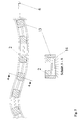
An fünf bevorzugten Ausführungsbeispielen wird der beste Weg zur Ausführung der beanspruchten Erfindung nachfolgend näher erläutert.
- Fig. 1
- zeigt die Darstellung einer Trocknung eines gesamten Raumes bzw. aller den Raum umgebenden Bauwerksteile.
- Fig. 2 und Fig. 3
- zeigen die Trocknung von Mauerwerksteilen.
- Fig. 4
- zeigt die Trocknung eines Flachdaches.
- Fig. 5
- zeigt die Trocknung von Fußböden mit einem flexiblen schlauchförmigen Geräteträger
- Fig. 1
- shows the representation of a drying of an entire room or all parts of the building surrounding the room.
- 2 and 3
- show the drying of masonry parts.
- Fig. 4
- shows the drying of a flat roof.
- Fig. 5
- shows the drying of floors with a flexible tubular device carrier
Zur Trocknung aller einen Raum umgebenden Wände 1 werden ein Resonator
4, der die Funktion der Schwingungsaussendung und -anregung bewirkt mit
einem Magnetron 2, welches die hochfrequenten elektromagnetischen Wellen
erzeugt, über einen Wellenleiter 3 verbunden und im Raum zentral aufgestellt.
Der Resonator 4 ist drehbar angeordnet, so daß die hochfrequente
Energiestrahlung alle Außen- und Innenwände 1 einschließlich Fußboden 1
und Decke 1 des Gebäudeteiles erreicht und in sie eindringt, wobei der
Angriffspunkt des Trocknungsverfahrens und seiner Anordnung nicht, wie
bisher außen an den Wandoberflächen, sondern in das Bauteilinnere gelegt
ist, d.h. die Wasserdampfdiffusion von innen nach außen bewirkt wird.
Die Durchdringtiefe wird durch die enthaltene Feuchtigkeit und das Material
des jeweiligen Bauteiles bestimmt. Diese Tiefe kann somit je
nach Bauteil sehr unterschiedlich sein, wodurch die Geschwindigkeit der
Austrocknung in den verschiedenen Bauteilen unterschiedlich sein wird.
In vorteilhafter Ausgestaltung der vorgeschlagenen Lehre kann es somit
auch zweckmäßig sein, eine unterschiedliche zeitliche Begrenzung kontinuierlicher
kombiniert mit impulsartiger gerichteter Bestrahlung bei der
Austrocknung eines Raumes vorzunehmen oder in Abhängigkeit von den jeweiligen
räumlichen Gegebenheiten mehrere Resonatoreelemente mit unterschiedlichem
Frequenzspektrum vorzusehen. Wenn ein Bauteil, z.B. eine
Innen wand 1 vor den anderen Bauteilen, z.B. den viel stärkeren Außenwänden
1 oder Decken 1 ausgetrocknet ist, wird dieses Bauwerksteil als
Wellenleiter wirksam und die Mikrowellenstrahlung dringt durch dieses
Bauwerksteil hindurch. Um beispielsweise Schädigungen der übrigen Umgebung,
so Nachbarräume oder Außenbereiche zu verhindern, ist es erforderlich,
daß Abschirmungen 5 in diesem Fall auch als Strahlungsreflektoren
8 in Form von z.B. metallischen Gittern oder Netzen den zu bestrahlenden
Raum umschließen. Dies wird gemäß der vorgeschlagenen erfinderischen
Lehre in diesem Ausführungsbeispiel durch bei der Bauerstellung unter
Putz eingearbeiteter Metallgitternetz erreicht. Die Energiezuführung zur
Trockenanordnung, die hier mehr als 25 kW beträgt, wird entweder über
einen Generator von außen oder mittels elektrischer Sicherheitseinrichtungen
vom Innenraum des Gebäudes realisiert. Die anfängliche Energieaufwendung
reduziert sich mit der Aufwandszeit um über 50 %. Im übrigen
werden die geltenden Sicherheitsvorschriften, so z.B. die DIN IEC 27(CO)
48 / VDE 0721 Teil 3011 anzuwenden sein, wodurch eine Sperrzone/Sicherheitszone
rund um den zu trocknenden Raum gelegt wird und die Leistungsdichte
des Strahles 14 so gestaltet ist, daß sie 50 W/m2 nicht überschreitet.To dry all the
Nasse Mauerwerksteile 1 werden mittels eines Magnetrons 2 mit Kühlsystem
2a und eines Generators (Netzteil) 6, die sich alle in einem
Gehäuse befinden, mit hochfrequenter Energiestrahlung beaufschlagt.
Mittels einer Zugeinrichtung 7 wird das Gehäuse mit den darin befindlichen
Magnetron 2, Kühlsystem 2a und Generator 6 sowie dem Reflektor
8, der aus einem Metallgitter, aus einer Metallplatte oder einem
Magneten mit vorgeschalteter Platte besteht und gegenüber des Magnetrons
2 positioniert ist, mit gleicher Geschwindigkeit am Mauerwerksteil 1
entlang bewegt.
Ein Magnetron (mit Kühlsystem) 2, das sich in einem Gehäuse befindet,
welches wiederum als Ziehschlitten 9 mit Rollrädern 10 ausgebildet und
mit einem Generator 6 verbunden ist, wird mittels Stahlseilen 7 an einem
Bauwerksteil 1, zum Beispiel einem Brückenpfeiler oder einer Staumauer,
mit definierter Geschwindigkeit von oben nach unten geführt. Damit wird
eine Trocknung an schwer zugänglichen Stellen ermöglicht.A magnetron (with cooling system) 2, which is located in a housing,
which in turn is designed as a
Zum Trocknen eines Flachdaches, großer Estrich- oder Fundamentflächen
oder auch Autobahnabschnitte 1 wird ebenfalls eine Anordnung in der Gestalt
eines Ziehschlittens 9 verwendet. Dieser Ziehschlitten 9 dient als
Geräteträger, der beliebig verlängerbar ist, die Magnetrone 2 mit Kühlsystem
enthält und an das Netzteil angeschlossen ist. Zur Durchführung
des Verfahrens wird dieser Ziehschlitten 9 auf einer Gleitbahn 11 über
die zu trocknende Fläche bewegt. Unter Ausnutzung der in die Bausubstanz
1 eingearbeiteten Bewehrung 12, die in diesem Falle als Reflektor und
Beschleuniger wirkt, wird die hier große Fläche in einem kurzen Zeitaufwand
getrocknet.For drying a flat roof, large screed or foundation areas
or also
In einem flexiblen Schlauchgebilde 13 sind eine bestimmte Anzahl verschiedener
Magnetrone 2, die mit dem Netzteil 6 verbunden sind, angeordnet.
Diese Magnetrone 2 können sowohl alle mit gleichem Frequenzspektrum
als auch jedes einzelne mit einem anderen Frequenzspektrum arbeiten.
An den betreffenden Bauwerksteilen oder -bereichen 1 können gegebenenfalls
Reflektoren am oder im auszutrocknenden Bereich angebracht
sein. Somit wird bewirkt, daß neben ebenen Bauwerksteilen, wie Fußböden,
wo die Anordnung wie ein Ziehschlitten benutzt wird, auch kompliziertere
Bauwerksbereiche, wie beispielsweise kompliziert gestaltete Fundamentteile,
Kanalisationen, Rohr- und Kabelschächte mit der vorgeschlagenen
technischen Lösung getrocknet werden können.In a
Claims (7)
- A device for drying out buildings, parts of buildings and/or fixed structures/components with the aid of high-frequency radiation, in particular, in the microwave range whereby the radiation generated by magnetrons is radiated by radiation emitters arranged directly at the magnetrons or linked with them via waveguides (3) and is reflected by appropriate shields,
characterised inthat the radiation emitters comprise oscillation-emitting resonator elements (4) in the form of antennas arranged centrally in the space, which fulfil the function of oscillation emitters to apply the electromagnetic waves to the structures/components or parts of buildings. - A device as claimed in Claim 1,
characterised inthat magnetrons (2) linked with their resonator elements (4) or these with the magnetrons (2) via waveguides (3) are arranged in flexible hose-style sliding (11) or rolling (10) racks (13) linked by one or several pull devices (7) designed partially as ropes. - A method for drying out buildings, parts of buildings and/or fixed structures/components with the aid of high-frequency radiation, in particular, in the microwave range, whereby the radiation generated by magnetrons is radiated by radiation emitters arranged directly at the magnetrons or linked with them via waveguides and is reflected by appropriate shielding elements,
characterised inthat magnetrons (2) acting as generators of high-frequency electromagnetic waves (14) are linked with resonator elements (4) via waveguides (3) and are installed in the building material (1) using shielding elements (5) and/or radiation reflectors (8),that the oscillation-emitting resonator elements (4) are incorporated into the building material (1) and the waveguides (3) are led to the surface of the building part or the building material (1) and end there in a joint,that the shielding elements (5), (8) in the form of metal foils or grid compounds are incorporated in the building material (1) already during their creation andthat the emission of the high-frequency radiation (14) is carried out limited in time, continuously or pulsed using resonator elements (4). - A method as claimed in Claim 3
characterised inthat metal objects or reinforcements used as resonator elements (4) are linked with the waveguides (3) of the magnetrons (2) already in the component/structure/part of building or building material (1) such that they can be removed. - A method as claimed in Claim 3
characterised inthat several resonator elements (4) are installed on or in a building (1) and each resonator element (4) emits the radiation at different frequency ranges. - A method as claimed in Claims 3 to 5
characterised inthat the frequency range of the resonator element (4) is changed depending on the radiation time. - A method as claimed in Claims 3 to 6
characterised inthat the radiation time is varied in steps or steplessly depending on material type and moisture in the building material to be dried out.
Applications Claiming Priority (3)
| Application Number | Priority Date | Filing Date | Title |
|---|---|---|---|
| DE19544889 | 1995-12-01 | ||
| DE19544889A DE19544889A1 (en) | 1995-12-01 | 1995-12-01 | Method and arrangement for drying buildings and / or stationary components |
| PCT/DE1996/002231 WO1997021060A1 (en) | 1995-12-01 | 1996-11-19 | Method and device for drying out buildings and/or fixed components |
Publications (2)
| Publication Number | Publication Date |
|---|---|
| EP0807235A1 EP0807235A1 (en) | 1997-11-19 |
| EP0807235B1 true EP0807235B1 (en) | 1999-09-22 |
Family
ID=7778959
Family Applications (1)
| Application Number | Title | Priority Date | Filing Date |
|---|---|---|---|
| EP96945890A Expired - Lifetime EP0807235B1 (en) | 1995-12-01 | 1996-11-19 | Method and device for drying out buildings and/or fixed components |
Country Status (9)
| Country | Link |
|---|---|
| EP (1) | EP0807235B1 (en) |
| AT (1) | ATE184984T1 (en) |
| CZ (1) | CZ223997A3 (en) |
| DE (2) | DE19544889A1 (en) |
| DK (1) | DK0807235T3 (en) |
| HU (1) | HUP9800815A3 (en) |
| NO (1) | NO973110L (en) |
| RU (1) | RU2170398C2 (en) |
| WO (1) | WO1997021060A1 (en) |
Cited By (1)
| Publication number | Priority date | Publication date | Assignee | Title |
|---|---|---|---|---|
| EP1374676A2 (en) | 2002-06-17 | 2004-01-02 | Silvia Hofmann | System and method for killing wood-destroying insects and mushrooms and for treating infected materials |
Families Citing this family (9)
| Publication number | Priority date | Publication date | Assignee | Title |
|---|---|---|---|---|
| SE517262C2 (en) | 1998-04-29 | 2002-05-14 | Leif Goesta Zettergren | Method for protection against microwave radiation when drying wet areas |
| DE19846611A1 (en) * | 1998-10-09 | 2000-04-13 | Prozesautomation Kohler Gmbh | Microwave drier with microwaves disconnected via surface radiator |
| DE19855555C2 (en) * | 1998-12-02 | 2001-03-15 | Linn High Therm Gmbh | Heating device |
| ITVI20020116A1 (en) * | 2002-06-03 | 2003-12-03 | Rf Systems Srl | DEVICE FOR HEATING AND / OR DRYING SURFACES |
| DE20209108U1 (en) | 2002-06-12 | 2002-09-05 | Kohler, Fritz, 35510 Butzbach | microwave dryers |
| DE10248666C1 (en) | 2002-10-16 | 2003-12-24 | Hartwig Pollinger | Process for drying boats made of wood and / or plastic materials |
| DE102006054355A1 (en) * | 2006-11-17 | 2008-06-05 | Büsch, Werner, Dipl.-Volksw. | Method and device for dehumidifying |
| DE202010001410U1 (en) * | 2010-01-25 | 2010-05-27 | Helmholtz-Zentrum Für Umweltforschung Gmbh - Ufz | Device for drying and decontamination of masonry, concrete, wood and other solids |
| DE102016107550B4 (en) * | 2016-04-22 | 2021-09-16 | Helmholtz-Zentrum Für Umweltforschung Gmbh - Ufz | Method and device for the thermal treatment of solids |
Family Cites Families (14)
| Publication number | Priority date | Publication date | Assignee | Title |
|---|---|---|---|---|
| DE276330C (en) * | ||||
| JPS5344065B2 (en) * | 1974-04-17 | 1978-11-25 | ||
| FR2571201B1 (en) * | 1984-10-02 | 1987-01-02 | Valeo | METHOD FOR HEATING IN THE MASS OF A SUBSTANCE FOR EXAMPLE FOR VULCANIZATION OR POLYMERIZATION |
| DE3644920A1 (en) * | 1986-03-07 | 1987-12-23 | Bosch Siemens Hausgeraete | Microwave oven |
| DE3623511A1 (en) * | 1986-07-11 | 1988-01-21 | Max Wagner | METHOD AND DEVICE FOR DRYING CERAMIC HOLLOW BODIES |
| US4765773A (en) * | 1987-02-27 | 1988-08-23 | Hopkins Harry C | Microwave highway paint drying apparatus |
| DK86888A (en) * | 1988-02-19 | 1989-08-20 | Winterthur Borgen A S | PROCEDURE FOR TREATING BUILDING CONSTRUCTIONS INFECTED WITH HARMFUL ORGANISMS TO DAMAGE THEM |
| DE4009691A1 (en) * | 1989-03-28 | 1990-10-04 | Gisip Inventor Ab | AIR DRYING BY MICROWAVE AND DEVICE THEREFOR |
| IT1245314B (en) * | 1990-06-21 | 1994-09-19 | Immobiliare Centro Nord Spa | PROCEDURE AND OVEN TO ACCELERATE THE SEASONING OF CEMENT CONGLOMERATES. |
| FR2664796A1 (en) * | 1990-07-18 | 1992-01-24 | Moreau Sa | Method for cleaning roots and tubers, especially beet, after they have been pulled out (lifted) |
| FI905484A (en) * | 1990-11-05 | 1992-05-06 | Rakennustoimisto Jukka Napari | TORKNINGSFOERFARANDE OCH -ANORDNING. |
| DE4200101A1 (en) * | 1992-01-03 | 1993-07-08 | Reinhard Schulze | Microwave application esp. for drying of stacked materials - provides simultaneous exposure of two or more loads having different coeffts. of absorption of microwaves |
| SE502580C2 (en) * | 1994-03-02 | 1995-11-13 | Leif Goesta Zettergren | Process and apparatus for mold remediation and drying of damp building parts |
| DE9413736U1 (en) * | 1994-06-14 | 1995-07-13 | AHRENS Bautechnologie Handelsgesellschaft mbH, 61118 Bad Vilbel | Microwave drying and pest control system |
-
1995
- 1995-12-01 DE DE19544889A patent/DE19544889A1/en not_active Ceased
-
1996
- 1996-11-19 RU RU97114448/06A patent/RU2170398C2/en active
- 1996-11-19 DK DK96945890T patent/DK0807235T3/en active
- 1996-11-19 EP EP96945890A patent/EP0807235B1/en not_active Expired - Lifetime
- 1996-11-19 CZ CZ972239A patent/CZ223997A3/en unknown
- 1996-11-19 WO PCT/DE1996/002231 patent/WO1997021060A1/en not_active Application Discontinuation
- 1996-11-19 AT AT96945890T patent/ATE184984T1/en not_active IP Right Cessation
- 1996-11-19 HU HU9800815A patent/HUP9800815A3/en unknown
- 1996-11-19 DE DE59603156T patent/DE59603156D1/en not_active Expired - Fee Related
-
1997
- 1997-07-04 NO NO973110A patent/NO973110L/en not_active Application Discontinuation
Cited By (1)
| Publication number | Priority date | Publication date | Assignee | Title |
|---|---|---|---|---|
| EP1374676A2 (en) | 2002-06-17 | 2004-01-02 | Silvia Hofmann | System and method for killing wood-destroying insects and mushrooms and for treating infected materials |
Also Published As
| Publication number | Publication date |
|---|---|
| WO1997021060A1 (en) | 1997-06-12 |
| DE19544889A1 (en) | 1997-06-05 |
| NO973110D0 (en) | 1997-07-04 |
| CZ223997A3 (en) | 1997-11-12 |
| DE59603156D1 (en) | 1999-10-28 |
| HUP9800815A3 (en) | 2002-07-29 |
| RU2170398C2 (en) | 2001-07-10 |
| HUP9800815A2 (en) | 1998-07-28 |
| EP0807235A1 (en) | 1997-11-19 |
| NO973110L (en) | 1997-09-26 |
| ATE184984T1 (en) | 1999-10-15 |
| DK0807235T3 (en) | 2000-03-27 |
Similar Documents
| Publication | Publication Date | Title |
|---|---|---|
| DE69110902T2 (en) | DRYING PROCEDURE. | |
| EP0807235B1 (en) | Method and device for drying out buildings and/or fixed components | |
| EP2225423B1 (en) | Composite cellulose element | |
| DE69108988T2 (en) | Device for hardening cement mixes. | |
| DE202010001410U1 (en) | Device for drying and decontamination of masonry, concrete, wood and other solids | |
| DE4319340C1 (en) | Process for producing mineral fibre insulation boards and an apparatus for carrying out the process | |
| DE4017057A1 (en) | CLAY PLATE AND METHOD FOR THEIR PRODUCTION | |
| DE69503610T2 (en) | MOBILE MICROWAVE DRYER | |
| DE4316901A1 (en) | Insulation material prodn. - by compacting mixt. of water glass and loose organic and/or inorganic particles followed by carbon di:oxide hardening | |
| WO2015132197A1 (en) | Drying device | |
| DE68908409T2 (en) | DEVICE AND METHOD FOR PRODUCING FIBER PANELS. | |
| DE3306044C2 (en) | ||
| DE102016107550B4 (en) | Method and device for the thermal treatment of solids | |
| WO1990001340A1 (en) | Process and heated conveyor for disinfecting contaminated, size-reduced hospital refuse | |
| DE69916447T2 (en) | SHIELDING AGENTS FOR MICROWAVES | |
| AT405845B (en) | METHOD FOR THE PRODUCTION OF A MINERAL FIBER LAMINATED SHEET AND DEVICE FOR IMPLEMENTING THE METHOD | |
| DE2502524A1 (en) | METHOD AND DEVICE FOR THERMAL TREATMENT OF OBJECTS USING HIGH FREQUENCY ELECTRIC FIELD | |
| DE3826273C2 (en) | ||
| DE19905186A1 (en) | Prefabricated interior insulating wall comprizes core plate of mineral insulation plus surface layers covered and bound to outer layers and installation channels within core plate. | |
| EP0563536A1 (en) | Insulating body and method for its production | |
| EP1390262B1 (en) | Method for producing a packaging and/or transport unit for plate-shaped insulating material consisting of mineral fibres, packaging and/or transport unit, and insulating plates | |
| DE19721795A1 (en) | Method for drying flat sections in buildings, such as walls, ceilings or similar | |
| DE2411743A1 (en) | COMPONENT AND PROCESS AND DEVICE FOR MANUFACTURING THESE TIES | |
| DE202010011832U1 (en) | Drying Device Using Microwave Energy to Reduce Moisture in Autoclaved Aerated Concrete Material (APB) | |
| DE29705222U1 (en) | Mobile ground defrosting device |
Legal Events
| Date | Code | Title | Description |
|---|---|---|---|
| PUAI | Public reference made under article 153(3) epc to a published international application that has entered the european phase |
Free format text: ORIGINAL CODE: 0009012 |
|
| 17P | Request for examination filed |
Effective date: 19970805 |
|
| AK | Designated contracting states |
Kind code of ref document: A1 Designated state(s): AT BE CH DE DK FI FR IT LI LU NL SE |
|
| 17Q | First examination report despatched |
Effective date: 19981026 |
|
| GRAG | Despatch of communication of intention to grant |
Free format text: ORIGINAL CODE: EPIDOS AGRA |
|
| GRAG | Despatch of communication of intention to grant |
Free format text: ORIGINAL CODE: EPIDOS AGRA |
|
| GRAH | Despatch of communication of intention to grant a patent |
Free format text: ORIGINAL CODE: EPIDOS IGRA |
|
| GRAH | Despatch of communication of intention to grant a patent |
Free format text: ORIGINAL CODE: EPIDOS IGRA |
|
| GRAA | (expected) grant |
Free format text: ORIGINAL CODE: 0009210 |
|
| AK | Designated contracting states |
Kind code of ref document: B1 Designated state(s): AT BE CH DE DK FI FR IT LI LU NL SE |
|
| REF | Corresponds to: |
Ref document number: 184984 Country of ref document: AT Date of ref document: 19991015 Kind code of ref document: T |
|
| REG | Reference to a national code |
Ref country code: CH Ref legal event code: EP |
|
| REF | Corresponds to: |
Ref document number: 59603156 Country of ref document: DE Date of ref document: 19991028 |
|
| ITF | It: translation for a ep patent filed | ||
| REG | Reference to a national code |
Ref country code: CH Ref legal event code: NV Representative=s name: BOVARD AG PATENTANWAELTE |
|
| ET | Fr: translation filed | ||
| REG | Reference to a national code |
Ref country code: DK Ref legal event code: T3 |
|
| PLBE | No opposition filed within time limit |
Free format text: ORIGINAL CODE: 0009261 |
|
| STAA | Information on the status of an ep patent application or granted ep patent |
Free format text: STATUS: NO OPPOSITION FILED WITHIN TIME LIMIT |
|
| 26N | No opposition filed | ||
| REG | Reference to a national code |
Ref country code: CH Ref legal event code: PUE Owner name: STEINBACH, DETLEF TRANSFER- ASTON AG |
|
| REG | Reference to a national code |
Ref country code: FR Ref legal event code: TP |
|
| NLS | Nl: assignments of ep-patents |
Owner name: ASTON AG |
|
| PGFP | Annual fee paid to national office [announced via postgrant information from national office to epo] |
Ref country code: FI Payment date: 20010927 Year of fee payment: 6 |
|
| PGFP | Annual fee paid to national office [announced via postgrant information from national office to epo] |
Ref country code: FR Payment date: 20010928 Year of fee payment: 6 |
|
| PGFP | Annual fee paid to national office [announced via postgrant information from national office to epo] |
Ref country code: DE Payment date: 20010929 Year of fee payment: 6 |
|
| PGFP | Annual fee paid to national office [announced via postgrant information from national office to epo] |
Ref country code: LU Payment date: 20011030 Year of fee payment: 6 Ref country code: AT Payment date: 20011030 Year of fee payment: 6 |
|
| PGFP | Annual fee paid to national office [announced via postgrant information from national office to epo] |
Ref country code: CH Payment date: 20011109 Year of fee payment: 6 |
|
| PGFP | Annual fee paid to national office [announced via postgrant information from national office to epo] |
Ref country code: BE Payment date: 20011121 Year of fee payment: 6 |
|
| PGFP | Annual fee paid to national office [announced via postgrant information from national office to epo] |
Ref country code: NL Payment date: 20011123 Year of fee payment: 6 |
|
| PGFP | Annual fee paid to national office [announced via postgrant information from national office to epo] |
Ref country code: DK Payment date: 20011127 Year of fee payment: 6 |
|
| PGFP | Annual fee paid to national office [announced via postgrant information from national office to epo] |
Ref country code: SE Payment date: 20011128 Year of fee payment: 6 |
|
| PG25 | Lapsed in a contracting state [announced via postgrant information from national office to epo] |
Ref country code: LU Free format text: LAPSE BECAUSE OF NON-PAYMENT OF DUE FEES Effective date: 20021119 Ref country code: FI Free format text: LAPSE BECAUSE OF NON-PAYMENT OF DUE FEES Effective date: 20021119 Ref country code: AT Free format text: LAPSE BECAUSE OF NON-PAYMENT OF DUE FEES Effective date: 20021119 |
|
| PG25 | Lapsed in a contracting state [announced via postgrant information from national office to epo] |
Ref country code: SE Free format text: LAPSE BECAUSE OF NON-PAYMENT OF DUE FEES Effective date: 20021120 |
|
| PG25 | Lapsed in a contracting state [announced via postgrant information from national office to epo] |
Ref country code: LI Free format text: LAPSE BECAUSE OF NON-PAYMENT OF DUE FEES Effective date: 20021130 Ref country code: CH Free format text: LAPSE BECAUSE OF NON-PAYMENT OF DUE FEES Effective date: 20021130 Ref country code: BE Free format text: LAPSE BECAUSE OF NON-PAYMENT OF DUE FEES Effective date: 20021130 |
|
| PG25 | Lapsed in a contracting state [announced via postgrant information from national office to epo] |
Ref country code: DK Free format text: LAPSE BECAUSE OF NON-PAYMENT OF DUE FEES Effective date: 20021231 |
|
| BERE | Be: lapsed |
Owner name: *STEINBACH DETLEF Effective date: 20021130 |
|
| PG25 | Lapsed in a contracting state [announced via postgrant information from national office to epo] |
Ref country code: NL Free format text: LAPSE BECAUSE OF NON-PAYMENT OF DUE FEES Effective date: 20030601 |
|
| PG25 | Lapsed in a contracting state [announced via postgrant information from national office to epo] |
Ref country code: DE Free format text: LAPSE BECAUSE OF NON-PAYMENT OF DUE FEES Effective date: 20030603 |
|
| EUG | Se: european patent has lapsed | ||
| REG | Reference to a national code |
Ref country code: DK Ref legal event code: EBP |
|
| REG | Reference to a national code |
Ref country code: CH Ref legal event code: PL |
|
| PG25 | Lapsed in a contracting state [announced via postgrant information from national office to epo] |
Ref country code: FR Free format text: LAPSE BECAUSE OF NON-PAYMENT OF DUE FEES Effective date: 20030731 |
|
| NLV4 | Nl: lapsed or anulled due to non-payment of the annual fee |
Effective date: 20030601 |
|
| REG | Reference to a national code |
Ref country code: FR Ref legal event code: ST |
|
| PG25 | Lapsed in a contracting state [announced via postgrant information from national office to epo] |
Ref country code: IT Free format text: LAPSE BECAUSE OF NON-PAYMENT OF DUE FEES Effective date: 20051119 |