EP0807204B1 - Seal arrangement for tubular tunnel segments - Google Patents
Seal arrangement for tubular tunnel segments Download PDFInfo
- Publication number
- EP0807204B1 EP0807204B1 EP96901220A EP96901220A EP0807204B1 EP 0807204 B1 EP0807204 B1 EP 0807204B1 EP 96901220 A EP96901220 A EP 96901220A EP 96901220 A EP96901220 A EP 96901220A EP 0807204 B1 EP0807204 B1 EP 0807204B1
- Authority
- EP
- European Patent Office
- Prior art keywords
- sealing
- groove
- profile
- sealing profile
- emergency seal
- Prior art date
- Legal status (The legal status is an assumption and is not a legal conclusion. Google has not performed a legal analysis and makes no representation as to the accuracy of the status listed.)
- Expired - Lifetime
Links
- 238000007789 sealing Methods 0.000 claims abstract description 113
- 239000003566 sealing material Substances 0.000 claims abstract description 11
- 230000015572 biosynthetic process Effects 0.000 claims abstract description 8
- 239000013536 elastomeric material Substances 0.000 claims abstract description 7
- 239000000463 material Substances 0.000 claims abstract description 6
- 229910001018 Cast iron Inorganic materials 0.000 claims abstract description 5
- 229910000831 Steel Inorganic materials 0.000 claims abstract description 5
- 239000004567 concrete Substances 0.000 claims abstract description 5
- 239000011150 reinforced concrete Substances 0.000 claims abstract description 5
- 239000010959 steel Substances 0.000 claims abstract description 5
- XLYOFNOQVPJJNP-UHFFFAOYSA-N water Substances O XLYOFNOQVPJJNP-UHFFFAOYSA-N 0.000 claims description 10
- 210000001331 nose Anatomy 0.000 claims 3
- 230000003247 decreasing effect Effects 0.000 claims 1
- 230000001747 exhibiting effect Effects 0.000 claims 1
- 238000000034 method Methods 0.000 abstract description 2
- 230000008961 swelling Effects 0.000 abstract description 2
- 230000013011 mating Effects 0.000 abstract 1
- 230000002093 peripheral effect Effects 0.000 abstract 1
- 230000000694 effects Effects 0.000 description 5
- 230000006835 compression Effects 0.000 description 2
- 238000007906 compression Methods 0.000 description 2
- 238000010276 construction Methods 0.000 description 2
- 238000002347 injection Methods 0.000 description 2
- 239000007924 injection Substances 0.000 description 2
- 230000003993 interaction Effects 0.000 description 2
- 230000004913 activation Effects 0.000 description 1
- 238000009435 building construction Methods 0.000 description 1
- 239000002131 composite material Substances 0.000 description 1
- 238000001746 injection moulding Methods 0.000 description 1
- 230000035515 penetration Effects 0.000 description 1
- 239000000243 solution Substances 0.000 description 1
- 229920003002 synthetic resin Polymers 0.000 description 1
- 239000000057 synthetic resin Substances 0.000 description 1
Images

Classifications
-
- E—FIXED CONSTRUCTIONS
- E21—EARTH OR ROCK DRILLING; MINING
- E21D—SHAFTS; TUNNELS; GALLERIES; LARGE UNDERGROUND CHAMBERS
- E21D11/00—Lining tunnels, galleries or other underground cavities, e.g. large underground chambers; Linings therefor; Making such linings in situ, e.g. by assembling
- E21D11/38—Waterproofing; Heat insulating; Soundproofing; Electric insulating
- E21D11/385—Sealing means positioned between adjacent lining members
Definitions
- the invention relates to a sealing arrangement consisting of two abutting components made of concrete, steel, reinforced concrete, cast iron or other materials (e.g. synthetic resins) and a sealing profile made of elastomeric material (i.e. rubber or rubber-like material), that seals the gap between the two components; being the components in particular are segments which are assembled into a tubular tunnel, and to form transverse and longitudinal joints, with each segment preferably with at least one circumferential recess encompassing all segment butt sides is provided, wherein in turn there is a strand-shaped sealing profile in each recess, the especially with strand-shaped groove grooves on the base side of the sealing profile are arranged, and / or is also provided with channels running in the form of a strand, and while forming a sealing frame with frame corners. Since the segments are mostly four Have butt sides, the sealing frame consists of four composite sealing profiles, whereby the frame corners are preferably produced by the injection molding process.
- a generic sealing arrangement is known for example from US-A-4 946 309.
- Such compression seals have been found in numerous Proven tunnel projects.
- EP-B-0 340 659 also presents a sealing arrangement in which the sealing profile is one Has cavity which is connected to an injection channel.
- the sealing profile is activated. In this way, one high sealing effect achieved without pressing the sealing profiles together during assembly would be required.
- the disadvantage here is the provision of an injection channel, which is frequent must also be guided through the segments, as well as additional device parts.
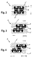
- the corners of the frame of the sealing frame are also at least are equipped with a groove that merges into the groove of the sealing profile, with regard to the advantageous design variants of the groove and the emergency seal according to the designs the numbers 1 to 3 is referred.
- FIG. 1 shows a tunnel 1 , consisting of segments 2 , namely with the formation of transverse and longitudinal joints 3 and 4 as well as a T-joint arrangement 5 .
- sealing arrangement 6 consisting of two abutting segments 2 ' and 2 " , each of which is provided with a recess 7, in each of which a sealing profile 8 made of elastomeric material is seated.
- the integrated emergency seal 9 comes in the optimal position ( compressed state of the two sealing profiles without misalignment) not to be carried in. The primary sealing effect is taken over by sealing profiles 8 (compression seals).
- the emergency seal consists in particular of a sealing material that can be activated with water, If there is humidity or water penetration, the additional Sealing effect to develop, due to a swelling process Volume increase of the emergency seal (activated seal).
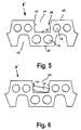
- Fig. 5 shows a sealing profile 8 '
- the back 10 is equipped with a single groove 11 which is located in the area of the profile center.
- the flanks 12 of this groove run conically, with the groove width narrowing towards the groove bottom 13 .
- the groove is provided with retaining lugs 14 which are arranged opposite one another within the flanks 12 , to be precise somewhat below the back 10 .
- FIG. 6 now shows the same sealing profile 8 ′ according to FIG. 5, but here the emergency seal 19 is seated in a strip shape, which has a trapezoidal shape when viewed in cross section and does not fill the entire groove, with the formation of a free space 20 .
- the retaining lugs 14 prevent the emergency seal 15 from falling out.
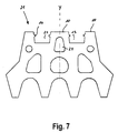
- the back 10 of the sealing profile 21 has two grooves 22 and 23 , which are arranged mirror-symmetrically (with respect to the vertical profile center plane Y) to one another, a channel 24 being located between these two grooves, in a total of three rows overall of grooves and channels.
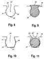
- FIG. 8 shows a groove 25 , the flanks 26 of which extend in an arc shape, and these also merge into the groove base 27 in an arc shape, to be precise with the formation of a groove with an essentially circular cross-sectional shape.
- the groove itself has an approximately funnel-shaped opening 28 .
- the groove according to FIG. 8 is now completely filled with the emergency seal 29 , the sealing surface 30 also having a flange-like widening, namely by encompassing the back 10 of the sealing profile.
- flank profile is shown, namely in the form of a concave flank 34 (dashed lines).
- FIG. 11 now shows a groove according to FIG. 10 with a double-conical flank profile, the emergency seal 35 seated in the groove being in the form of a cord, with an essentially circular cross-sectional shape.
- the sealing surface 36 of the emergency seal is located here to form a free space 37 somewhat below the back 10 of the sealing profile, and as a variant an aligned course of the sealing surface 36 ' with the back 10 is also possible (dashed lines).
Landscapes
- Engineering & Computer Science (AREA)
- Structural Engineering (AREA)
- Mining & Mineral Resources (AREA)
- General Life Sciences & Earth Sciences (AREA)
- Civil Engineering (AREA)
- Life Sciences & Earth Sciences (AREA)
- Architecture (AREA)
- Geochemistry & Mineralogy (AREA)
- Geology (AREA)
- Lining And Supports For Tunnels (AREA)
- Bridges Or Land Bridges (AREA)
- Shaping Of Tube Ends By Bending Or Straightening (AREA)
- Lining Or Joining Of Plastics Or The Like (AREA)
- Pipe Accessories (AREA)
- Road Paving Structures (AREA)
Abstract
Description
Die Erfindung betrifft eine Dichtanordnung, bestehend aus zwei aneinanderstoßenden Bauteilen aus Beton, Stahl, Stahlbeton, Gußeisen oder anderen Materialien (z.B. Kunstharze) sowie aus einem Dichtprofil aus elastomerem Werkstoff (d.h. aus Gummi oder gummiähnlichem Werkstoff), das den Spalt zwischen den beiden Bauteilen abdichtend überbrückt; wobei die Bauteile insbesondere Segmente sind, die zu einem rohrförmigen Tunnel zusammengesetzt sind, und zwar unter Bildung von Quer- und Längsfugen, wobei jedes Segment vorzugsweise mit wenigstens einer alle Segmentstoßseiten erfassenden umlaufenden Aussparung versehen ist, wobei sich wiederum in jeder Aussparung ein strangförmig verlaufendes Dichtprofil befindet, das insbesondere mit strangförmig verlaufenden Rillennuten, die an der Basisseite des Dichtprofiles angeordnet sind, und / oder mit ebenfalls strangförmig verlaufenden Kanälen versehen ist, und zwar unter Bildung eines Dichtrahmens mit Rahmenecken. Da die Segmente zumeist vier Stoßseiten besitzen, besteht der Dichtrahmen aus vier zusammengesetzten Dichtprofilen, wobei die Rahmenecken vorzugsweise nach dem Injection-Molding-Verfahren hergestellt werden.The invention relates to a sealing arrangement consisting of two abutting components made of concrete, steel, reinforced concrete, cast iron or other materials (e.g. synthetic resins) and a sealing profile made of elastomeric material (i.e. rubber or rubber-like material), that seals the gap between the two components; being the components in particular are segments which are assembled into a tubular tunnel, and to form transverse and longitudinal joints, with each segment preferably with at least one circumferential recess encompassing all segment butt sides is provided, wherein in turn there is a strand-shaped sealing profile in each recess, the especially with strand-shaped groove grooves on the base side of the sealing profile are arranged, and / or is also provided with channels running in the form of a strand, and while forming a sealing frame with frame corners. Since the segments are mostly four Have butt sides, the sealing frame consists of four composite sealing profiles, whereby the frame corners are preferably produced by the injection molding process.
Eine gattungsgemäße Dichtanordnung ist beispielsweise aus der US-A-4 946 309 bekannt. Infolge des Zusammenpressens der aneinanderstoßenden Bauteile bzw. Segmente unter Verringerung des Abstandes des Spaltes bzw. der Quer- und Längsfugen entfaltet dann das Dichtprofil aus elastomerem Werkstoff unter der Wechselwirkung von Kraft und Reaktionskraft seine Dichtleistung. Derartige Kompressionsdichtungen haben sich bei zahlreichen Tunnelprojekten bewährt.A generic sealing arrangement is known for example from US-A-4 946 309. As a result of the pressing together of the abutting components or segments Reducing the distance of the gap or the transverse and longitudinal joints then unfolds that Sealing profile made of elastomeric material under the interaction of force and reaction force its sealing performance. Such compression seals have been found in numerous Proven tunnel projects.
Zwecks zusätzlicher Druckaktivierung ist ferner vorgeschlagen worden, ein Dichtprofil zur Wasserseite hin mit einer seitlichen Bohrung zu versehen, die mit wenigstens einem der strangförmig verlaufenden Kanälen verbunden ist (US-A-5 044 823). Bei Eindringen von Wasser von der Segment-Außenseite herz wird der Kanal bzw. die Kanäle durch den Wasserdruck gestützt, was zu einer Erhöhung der Dichtleistung führt. Nachteilig ist jedoch, daß die Bohrung durch Verschmutzung geschlossen werden kann, was die Unwirksamkeit dieser druckaktivierenden Zusatzmaßnahme zur Folge hat.For the purpose of additional pressure activation, a sealing profile has also been proposed To provide water side with a side hole that with at least one of the strand-shaped channels is connected (US-A-5 044 823). When water penetrates from the outside of the segment, the canal (s) becomes water pressure supported, which leads to an increase in sealing performance. The disadvantage, however, is that the bore can be concluded by pollution, making the ineffectiveness of this pressure-activating additional measure.
In der EP-B-0 340 659 wird ferner eine Dichtanordnung vorgestellt, bei der das Dichtprofil einen Hohlraum aufweist, der mit einem Injektionskanal verbunden ist. Mittels eines injizierbaren, das Gesamtvolumen vergrößernden Mediums wird das Dichtprofil aktiviert. Auf diese Weise wird eine hohe Dichtwirkung erzielt, ohne daß ein Zusammenpressen der Dichtprofile bei der Montage erforderlich wäre. Nachteilig ist hier jedoch die Bereitstellung eines Injekfionskanales, der häufig zudem durch die Segmente geführt werden muß, sowie zusätzlicher Vorrichtungsteile.EP-B-0 340 659 also presents a sealing arrangement in which the sealing profile is one Has cavity which is connected to an injection channel. By means of an injectable, the Total volume increasing medium, the sealing profile is activated. In this way, one high sealing effect achieved without pressing the sealing profiles together during assembly would be required. However, the disadvantage here is the provision of an injection channel, which is frequent must also be guided through the segments, as well as additional device parts.
In den französischen Offenlegungsschriften 2 669 259, 2 678 680 und 2 712 655 werden
Dichtanordnungen vorgestellt, bei denen der Rücken des Dichtprofiles wenigstens eine
strangförmig verlaufende Nut aufweist, die für die Aufnahme einer Notdichtung, insbesondere
eines aktivierbaren, insbesondere wiederum eines mit Wasser aktivierbaren Dichtmaterials,
vorgesehen ist. Der Rücken des Dichtprofiles kann dabei eine einzige Nut aufweisen. Eine
weitere Möglichkeit besteht darin, den Rücken des Dichtprofiles mit zwei Nuten auszustatten,
die im wesentlichen spiegelssymmetrisch zueinander angeordnet sind, und zwar bezogen auf
die senkrechte Profilmittelebene (EP-A-0 522 912).In
Trotz zahlreicher Lösungsvorschläge beim Abdichten aneinanderstoßender Bauteile gibt es bislang ein unzureichend gelöstes Problem. Bauteile, insbesondere Tunnel-Segmente, können sich mit der Zeit (z.B. unter Einwirkung von geologischen Änderungsbedingungen) in ihrer Lage zueinander verändern, beispielsweise durch Ovalisierung, so daß sich Spalte auftun. Ferner können Bauteile bzw. Tunnel-Segmente bei Einbau unter Versatz verschoben sein. Derartige Konstellationen führen dann zwangsläufig zu einer negativen Beeinflussung der Dichtwirkung des Dichtprofiles.Despite numerous proposed solutions for sealing abutting components, there are an inadequately solved problem. Components, especially tunnel segments, can changes in position over time (e.g. under the influence of geological change conditions) change to each other, for example by ovalization, so that gaps open. Further components or tunnel segments can be displaced when installed under offset. Such Constellations then inevitably lead to a negative influence on the sealing effect of the sealing profile.
Aus diesem Grunde wird erfindungsgemäß eine Dichtanordnung vorgeschlagen, bei der der
Rücken des Dichtprofiles wenigstens eine strangförmig verlaufende Nut mit den
kennzeichnenden Merkmalen des Anspruches 1, 2 oder 3
aufweist.For this reason, a sealing arrangement is proposed according to the invention, in which the
Back of the sealing profile at least one strand-shaped groove with the
characterizing features of
Hinsichtlich der konstruktiven Gestaltung der Nut wie auch der in ihr einsitzenden Notdichtung
kommen folgende Varianten zum Einsatz.
Es ist ferner zweckmäßig, wenn die Rahmenecken des Dichtrahmens ebenfalls mit wenigstens
einer Nut ausgestattet sind, die fluchtend in die Nut des Dichtprofiles übergeht, wobei hinsichtlich
der vorteilhaften Gestaltungsvarianten der Nut und der Notdichtung auf die Ausführungen gemäß
der Ziffern 1 bis 3 verwiesen wird.It is also expedient if the corners of the frame of the sealing frame are also at least
are equipped with a groove that merges into the groove of the sealing profile, with regard to
the advantageous design variants of the groove and the emergency seal according to the designs
the
Es ist zudem zweckmäßig, wenn die Notdichtung erst unmittelbar vor dem Zusammenfügen der Bauteile bzw. der Segmente in die Nut eingesetzt wird. Dies ist insbesondere von Bedeutung bei einer Notdichtung, die aus mit Wasser aktivierbarem Dichtmaterial (z.B. Hydrotite®) besteht.It is also useful if the emergency seal only immediately before the assembly of the Components or the segments is inserted into the groove. This is particularly important for an emergency seal consisting of sealing material that can be activated with water (e.g. Hydrotite®).
Weitere konstruktive Gestaltungsvarianten des Dichtprofiles werden im Rahmen der Figurenbeschreibung vorgestellt.Further constructive design variants of the sealing profile are part of the Figure description presented.
Die Erfindung wird nun anhand von Ausführungsbeispielen unter Bezugnahme auf schematische
Zeichnungen erläutert. Es zeigen:
Die Fig. 2 bis 4 beinhalten dabei eine Querschnittsdarstellung der Längsfuge gemäß der Schnittlinie A-A (Fig. 1). Obwohl die Rillennuten und Kanäle im belasteten Zustand (d.h. unter Druckwirkung) ihre Form ändern, sind diese Profilteile im Rahmen der schematischen Zeichnungen in ihrer ursprünglichen Form dargestellt.2 to 4 include a cross-sectional view of the longitudinal joint according to the Section line A-A (Fig. 1). Although the groove and channels are under load (i.e. under Pressure effect) change their shape, these profile parts are part of the schematic Drawings shown in their original form.
Die Fig. 5 bis 11 stellen dagegen den unbelasteten Zustand dar. Das gleiche gilt auch für die in den Ansprüchen niedergelegten konstruktiven Beschreibungen des Dichtprofiles, der Nut und der Notdichtung.5 to 11, on the other hand, show the unloaded state. The same also applies to the in the claims laid down constructive descriptions of the sealing profile, the groove and the emergency seal.
In Verbindung mit diesen Figuren gilt folgende Bezugsziffernliste.
- 1
- Tunnel
- 2
- Segment
- 2'
- Segment
- 2"
- Segment
- 3
- Querfuge (Ringfuge)
- 4
- Längsfuge
- 5
- T-Stoßanordnung
- 6
- Dichtanordnung
- 7
- Aussparung
- 8
- Dichtprofil
- 8'
- Dichtprofil
- 9
- Notdichtung
- 10
- Rücken des Dichtprofiles
- 11
- Nut
- 12
- Flanke
- 13
- Nutboden
- 14
- Haltenase
- 15
- Basisseite des Dichtprofiles
- 16
- Kanal
- 17
- Rillennut
- 18
- Kanal
- 19
- Notdichtung in Streifenform
- 20
- Freiraum
- 21
- Dichtprofil
- 22
- Nut
- 23
- Nut
- 24
- Kanal
- 25
- Nut
- 26
- Flanke
- 27
- Nutboden
- 28
- trichterförmige Öffnung
- 29
- Notdichtung
- 30
- Dichtfläche mit flanschförmiger Verbreiterung
- 31
- Nut
- 32
- Flanke
- 32'
- Flanke
- 33
- Nutboden
- 34
- Flanke
- 35
- Notdichtung
- 36
- Dichtfläche
- 36'
- Dichtfläche
- 37
- Freiraum
- 1
- tunnel
- 2nd
- segment
- 2 '
- segment
- 2 "
- segment
- 3rd
- Transverse joint (ring joint)
- 4th
- Longitudinal joint
- 5
- T-joint arrangement
- 6
- Sealing arrangement
- 7
- Recess
- 8th
- Sealing profile
- 8th'
- Sealing profile
- 9
- Emergency seal
- 10th
- Back of the sealing profile
- 11
- Groove
- 12th
- Flank
- 13
- Groove bottom
- 14
- Holding nose
- 15
- Base side of the sealing profile
- 16
- channel
- 17th
- Groove groove
- 18th
- channel
- 19th
- Emergency seal in strip form
- 20th
- free space
- 21
- Sealing profile
- 22
- Groove
- 23
- Groove
- 24th
- channel
- 25th
- Groove
- 26
- Flank
- 27
- Groove bottom
- 28
- funnel-shaped opening
- 29
- Emergency seal
- 30th
- Sealing surface with flange-shaped widening
- 31
- Groove
- 32
- Flank
- 32 '
- Flank
- 33
- Groove bottom
- 34
- Flank
- 35
- Emergency seal
- 36
- Sealing surface
- 36 '
- Sealing surface
- 37
- free space
Fig. 1 zeigt einen Tunnel 1, bestehend aus Segmenten 2, und zwar unter Bildung von Quer- und
Längsfugen 3 bzw. 4 sowie einer T-Stoßanordnung 5.1 shows a
Fig. 2 zeigt eine Dichtanordnung 6, bestehend aus zwei aneinanderstoßenden Segmenten 2'
und 2", die jeweils mit einer Aussparung 7 versehen sind, in der wiederum jeweils ein
Dichtprofil 8 aus elastomerem Werkstoff einsitzt. Die integrierte Notdichtung 9 kommt in der
optimalen Position (zusammengepreßter Zustand der beiden Dichtprofile ohne Versatz) zunächst
nicht zum Tragen. Die primäre Dichtwirkung übernehmen hier die Dichtprofile 8
(Kompressionsdichtungen).2 shows a sealing
Die Notdichtung 9 kommt erfindungsgemäß dann zum Einsatz, wenn sich folgende
Konstellationen ergeben.
Da die Notdichtung insbesondere aus einem mit Wasser aktivierbaren Dichtmaterial besteht, kann bei vorhandener Luftfeuchtigkeit bzw. bei eindringendem Wasser die zusätzliche Dichtwirkung zur Enffaltung gelangen, und zwar infolge eines Quellvorganges unter Volumenvergrößerung der Notdichtung (aktivierte Dichtung).Since the emergency seal consists in particular of a sealing material that can be activated with water, If there is humidity or water penetration, the additional Sealing effect to develop, due to a swelling process Volume increase of the emergency seal (activated seal).
Fig. 5 zeigt ein Dichtprofil 8', dessen Rücken 10 mit einer einzigen Nut 11 ausgestattet ist, die
sich im Bereich der Profilmitte befindet. Die Flanken 12 dieser Nut verlaufen konisch, und zwar
unter Verkleinerung der Nutbreite zum Nutboden 13 hin. Die Nut ist dabei mit Haltenasen 14
versehen, die innerhalb der Flanken 12, und zwar etwas unterhalb des Rückens 10,
gegenüberliegend angeordnet sind. Fig. 5 shows a sealing profile 8 ' , the back 10 is equipped with a single groove 11 which is located in the area of the profile center. The
Zwischen dem im wesentlichen ebenflächigen Nutboden 13 und der Basisseite 15 des
Dichtprofiles sind zwei Kanäle 16 vorhanden, die von zwei Rillennuten 17 eingerahmt sind.
Außerdem sind beidseitig zur Nut 11 jeweils zwei weitere Kanäle 18 angeordnet.Between the essentially flat groove bottom 13 and the
Fig. 6 zeigt nun das gleiche Dichtprofil 8' gemäß Fig. 5, wobei hier jedoch die Notdichtung 19 in
Streifenform einsitzt, die im Querschnitt gesehen eine trapezförmige Gestalt aufweist und nicht
die gesamte Nut ausfüllt, und zwar unter Bildung eines Freiraumes 20. Die Haltenasen 14
verhindern dabei das Herausfallen der Notdichtung 15.FIG. 6 now shows the
Nach Fig. 7 weist der Rücken 10 des Dichtprofiles 21 zwei Nuten 22 und 23 auf, die
spiegelsymmetrisch (bezogen auf die senkrechte Profilmittelebene Y) zueinander angeordnet
sind, wobei sich zwischen diesen beiden Nuten ein Kanal 24 befindet, und zwar bei einer
insgesamt dreireihigen Gesamtanordnung von Rillen und Kanälen. Hinsichtlich des
Zusammenwirkens von Haltenasen 14 und Notdichtung wird auf die Fig. 6 verwiesen.7, the back 10 of the sealing
Fig. 8 zeigt eine Nut 25, deren Flanken 26 bogenförmig verlaufen, wobei diese zudem
bogenförmig in den Nutboden 27 übergehen, und zwar unter Bildung einer Nut mit einer im
wesentlichen kreisförmigen Querschnittsgestalt. Die Nut selbst besitzt eine etwa trichterförmige
Öffnung 28.FIG. 8 shows a
Nach Fig. 9 ist nun die Nut gemäß Fig. 8 vollständig mit der Notdichtung 29 ausgefüllt, wobei die
Dichtfläche 30 zudem eine flanschförmige Verbreiterung aufweist, und zwar unter Umgreifung
des Rückens 10 des Dichtprofiles.According to FIG. 9, the groove according to FIG. 8 is now completely filled with the
Fig. 10 zeigt nun eine Nut 31, deren Flanken 32 bzw. 32' doppelkonisch verlaufen, wobei die
Nutbreite im Bereich der halben Nuttiefe am größten ist, und zwar bei einem im wesentlichen
ebenflächigen Nutboden 33.10 now shows a
Im Rahmen dieser Figuren ist eine weitere Alternative des Flankenverlaufes dargestellt, und zwar in Form einer konkav verlaufenden Flanke 34 (gestrichelte Linienführung).In the context of these figures, a further alternative of the flank profile is shown, namely in the form of a concave flank 34 (dashed lines).
Fig. 11 zeigt nun eine Nut gemäß Fig. 10 mit doppelkonischem Flankenverlauf, wobei die in der
Nut einsitzende Notdichtung 35 in Schnurform vorliegt, und zwar mit im wesentlichen
kreisförmiger Querschnittsgestalt. Die Dichtfläche 36 der Notdichtung befindet sich hier unter
Bildung eines Freiraumes 37 etwas unterhalb des Rückens 10 des Dichtprofiles, wobei als
Variante auch ein fluchtender Verlauf der Dichtfläche 36' mit dem Rücken 10 möglich ist
(gestrichelte Linienführung).11 now shows a groove according to FIG. 10 with a double-conical flank profile, the
Auch wenn der erfindungsgemäßen Dichtanordnung im Rahmen des Tunnelbaues eine herausragende Bedeutung zukommt, so läßt sich dieses Prinzip auch auf andere Baukonstruktionen anwenden, beispielsweise beim Abdichten von Muffenrohren beim Kanalbau (EP-B-0 449 082).Even if the sealing arrangement according to the invention in the context of tunnel construction this principle can also be applied to others Use building constructions, for example when sealing socket pipes in sewer construction (EP-B-0 449 082).
Claims (12)
- A sealing arrangement (6) which consists ofcharacterized in thattwo abutting components of concrete, steel, reinforced concrete, cast iron or other materials as well as of a sealing profile of elastomeric material bridging over the gap between the two components;where the components are in particular segments (2,2',2") assembled into a tubular tunnel (1), that is, with the formation of transverse and longitudinal joints (3) resp. (4), each segment being preferably provided at its abutting edge with at least one recess (7) running round to take in all of the abutting edges of the segment, and where there is again in each recess a continuous sealing profile (8,8',21) provided in particular with continuous grooves arranged at the side of the sealing profile at the base and/or with likewise continuous channels, that is, to form a sealing frame with frame corners;where again the back (10) of the sealing profile (8,8',21) exhibits at least one continuous groove (11,22,23,25,31) which is designed to receive an emergency seal (9,19,29,35), especially one of sealing material which may be activated, again especially of sealing material which activates in water;the flanks (26) of the groove (25) run in an arc and in addition continue into the bottom (27) of the groove in an arc, thus forming a groove with an essentially circular cross-sectional shape, the groove being provided in particular with a roughly funnel-shaped opening (28).
- A sealing arrangement (6) which consists ofcharacterized in thattwo abutting components of concrete, steel, reinforced concrete, cast iron or other materials as well as of a sealing profile of elastomeric material bridging over the gap between the two components;where the components are in particular segments (2,2',2") assembled into a tubular tunnel (1), that is, with the formation of transverse and longitudinal joints (3) resp. (4), each segment being preferably provided at its abutting edge with at least one recess (7) running round to take in all of the abutting edges of the segment, and where there is again in each recess a continuous sealing profile (8,8',21) provided in particular with continuous grooves arranged at the side of the sealing profile at the base and/or with likewise continuous channels, that is, to form a sealing frame with frame corners;where again the back (10) of the sealing profile (8,8',21) exhibits at least one continuous groove (11,22,23,25,31) which is designed to receive an emergency seal (9,19,29,35), especially one of sealing material which may be activated, again especially of sealing material which activates in water;the flanks (32,32',34) of the groove (31) run in a double cone or are concave with the width of the groove greatest in the region of half the depth of the groove, and there is an essentially plane bottom (33) to the groove.
- A sealing arrangement (6) which consists ofcharacterized in thattwo abutting components of concrete, steel, reinforced concrete, cast iron or other materials as well as of a sealing profile of elastomeric material bridging over the gap between the two components;where the components are in particular segments (2,2',2") assembled into a tubular tunnel (1), that is, with the formation of transverse and longitudinal joints (3) resp. (4), each segment being preferably provided at its abutting edge with at least one recess (7) running round to take in all of the abutting edges of the segment, and where there is again in each recess a continuous sealing profile (8,8',21) provided in particular with continuous grooves arranged at the side of the sealing profile at the base and/or with likewise continuous channels, that is, to form a sealing frame with frame corners;where again the back (10) of the sealing profile (8,8',21) exhibits at least one continuous groove (11,22,23,25,31) which is designed to receive an emergency seal (9,19,29,35), especially one of sealing material which may be activated, again especially of sealing material which activates in water;the flanks (12) of the groove (11,22,23) run in a cone, that is, with the width of the groove decreasing towards the bottom of the groove and there is an essentially plane bottom (13) to the groove, whilst the groove is equipped with continuous retainer noses (14) which prevent the emergency seal (19) from dropping out, that is, because there is one single retainer nose (14) inside each flank (12) of the groove (11,22,23) and the two opposing retainer noses are arranged a little below the back (10) of the sealing profile (8',21).
- A sealing arrangement as in Claim 1, 2 or 3, characterized in that the back (10) of the sealing profile (8,8') exhibits one single groove (11) which lies in the region of the centre of the profile.
- A sealing arrangement as in Claim 1, 2 or 3, characterized in that the back (10) of the sealing profile (21) exhibits two grooves (22, 23) arranged essentially with mirror symmetry with respect to one another about the vertical central plane Y of the profile, and at least one channel (24) is arranged between the pair of grooves (22,23).
- A sealing arrangement as in one of the Claims 1 to 5, especially in combination with Claim 3, characterized in that the emergency seal (19) is in the form of a strip, that is, with an essentially rectangular or trapezoidal cross-sectional shape.
- A sealing arrangement as in one of the Claims 1 to 5, especially in combination with Claims 1 or 2, characterized in that the emergency seal (35) is in the form of a cord, that is, with an essentially circular cross-sectional shape.
- A sealing arrangement as in one of the Claims 1 to 7, characterized in that the emergency seal (19,35) does not occupy the whole groove, so a free space (20,37) is formed between the back (10) of the sealing profile and the emergency seal.
- A sealing arrangement as in one of the Claims 1 to 7, characterized in that the emergency seal (35) essentially fills the groove fully, with the upper sealing face (36') of the emergency seal running about flush with the back (10) of the sealing profile.
- A sealing arrangement as in one of the Claims 1 to 7, characterized in that the emergency seal (29) essentially fills the groove fully, with the upper sealing face (30) exhibiting a widening in the form of a flange, that is, so as to embrace the the back (10) of the sealing profile.
- A sealing arrangement as in one of the Claims 1 to 10, characterized in that the frame corners of the sealing frame are likewise equipped with at least one groove which continues straight into the groove in the sealing profile.
- A sealing arrangement as in one of the Claims 1 to 11, characterized in that the emergency seal is inserted in the groove directly before the components or segments are joined together.
Applications Claiming Priority (3)
| Application Number | Priority Date | Filing Date | Title |
|---|---|---|---|
| DE19502991 | 1995-02-01 | ||
| DE19502991 | 1995-02-01 | ||
| PCT/DE1996/000123 WO1996023958A1 (en) | 1995-02-01 | 1996-01-30 | Seal arrangement for tubular tunnel segments |
Publications (2)
| Publication Number | Publication Date |
|---|---|
| EP0807204A1 EP0807204A1 (en) | 1997-11-19 |
| EP0807204B1 true EP0807204B1 (en) | 1999-04-07 |
Family
ID=7752736
Family Applications (1)
| Application Number | Title | Priority Date | Filing Date |
|---|---|---|---|
| EP96901220A Expired - Lifetime EP0807204B1 (en) | 1995-02-01 | 1996-01-30 | Seal arrangement for tubular tunnel segments |
Country Status (8)
| Country | Link |
|---|---|
| US (1) | US5888023A (en) |
| EP (1) | EP0807204B1 (en) |
| JP (1) | JP2796437B2 (en) |
| AT (1) | ATE178691T1 (en) |
| AU (1) | AU734698B2 (en) |
| DE (2) | DE19603188A1 (en) |
| ES (1) | ES2132879T3 (en) |
| WO (1) | WO1996023958A1 (en) |
Cited By (1)
| Publication number | Priority date | Publication date | Assignee | Title |
|---|---|---|---|---|
| US6575664B1 (en) | 1999-09-14 | 2003-06-10 | Phoenix Ag | Sealing arrangement |
Families Citing this family (23)
| Publication number | Priority date | Publication date | Assignee | Title |
|---|---|---|---|---|
| ES2122802T3 (en) * | 1995-03-01 | 1998-12-16 | Phoenix Ag | SEALING BOARD AND ITS PROCEDURE FOR CARRYING OUT IT. |
| DE19826482A1 (en) * | 1997-07-08 | 1999-01-14 | Phoenix Ag | Seal for two abutting elements used in tunnel building |
| US6592296B2 (en) * | 2000-03-30 | 2003-07-15 | Phoenix | Sealing assembly for tunnel construction sections |
| ES2254581T3 (en) | 2001-10-11 | 2006-06-16 | Datwyler Ag Schweizerische Kabel-, Gummi- Und Kunststoffwerke | SHUTTER PROFILE FOR TUNNEL SEGMENTS. |
| US6692039B2 (en) | 2002-02-08 | 2004-02-17 | Hunting Hti Rehab, Inc., Llc | Internal conduit sealing installation |
| US20060186662A1 (en) * | 2005-02-23 | 2006-08-24 | Vertex, Inc. | Cast-in-place gasket for pipe joints |
| ES2340300T3 (en) * | 2005-08-18 | 2010-06-01 | Phoenix Dichtungstechnik Gmbh | TOBACCO ASSEMBLY COMPOSED BY DIFFERENT TYPES OF POLYMER MATERIALS. |
| US7922179B2 (en) * | 2006-02-21 | 2011-04-12 | Vertex, Inc. | Cast-in-place gasket for pipe joints |
| US20080106044A1 (en) * | 2006-11-07 | 2008-05-08 | Ngoc Minh Luong | Sealing system and gasket with spaces |
| US7722293B2 (en) * | 2008-01-28 | 2010-05-25 | Darin R. Kruse | Methods for constructing underground structures |
| DE102009056063A1 (en) * | 2009-11-30 | 2011-07-14 | Phoenix Dichtungstechnik GmbH, 99880 | Sealing arrangement for shaft and tunnel constructions |
| DE102009057521B4 (en) * | 2009-12-10 | 2011-07-21 | Bochumer Eisenhütte Heintzmann GmbH & Co. KG, 44793 | Tubbing extension with integrated compliance element |
| CA2837863C (en) | 2011-06-03 | 2020-07-28 | Darin R. Kruse | Lubricated soil mixing systems and methods |
| DE102012106462A1 (en) | 2012-07-18 | 2014-01-23 | Dätwyler Sealing Technologies Deutschland Gmbh | Formwork mold assembly used for producing molded article from thermosetting material, has sealing strip that is attached on wall of support contacting back side of recess and/or projection, opposite to base side of anchoring foot |
| DE202012102753U1 (en) | 2012-07-23 | 2013-07-24 | Dätwyler Sealing Technologies Deutschland Gmbh | Puller |
| US9556734B2 (en) | 2014-01-08 | 2017-01-31 | Csi Tunnel Systems | Tunnel segment cross gasket |
| NL2012765B1 (en) * | 2014-05-06 | 2016-02-23 | Trelleborg Ridderkerk B V | Method for producing a construction element, in particular a tunnel element, having a watertight seal. |
| WO2017201289A1 (en) * | 2016-05-18 | 2017-11-23 | Vintech Industriesa, Inc. | Seals and method for making same |
| DE102017006656A1 (en) * | 2017-07-13 | 2019-01-17 | Lars Hiob | PCR Cuff (Perfect Connect Removable Cuff) |
| US11401810B2 (en) * | 2018-01-19 | 2022-08-02 | Vertex, Inc. | Removable and replaceable anchored tunnel gasket |
| CN109469495A (en) * | 2018-12-26 | 2019-03-15 | 天津大学 | A shield tunnel segment seam gasket with concave-convex section |
| CN110159318B (en) * | 2019-05-30 | 2020-10-23 | 东北大学 | A shield tunnel composite waterproof structure |
| CN112227581B (en) * | 2020-10-09 | 2022-05-17 | 中建科工集团有限公司 | A board seam leak-proof structure, fabricated roof panel and fabricated roof panel system |
Family Cites Families (20)
| Publication number | Priority date | Publication date | Assignee | Title |
|---|---|---|---|---|
| US3046028A (en) * | 1959-12-01 | 1962-07-24 | Hamilton Kent Mfg Company | Gasket and use thereof |
| US3052196A (en) * | 1961-09-22 | 1962-09-04 | Chace D Gilmore | Seal bearing rings for doughnut cutters |
| US3695044A (en) * | 1969-04-12 | 1972-10-03 | Masahiro Hoshino | Sealing method of sealed segments of a tunnel |
| NL164945C (en) * | 1977-11-23 | 1981-02-16 | Vredestein Nv | SEALING PROFILE FOR A SUN-TUNNEL. |
| CH629869A5 (en) * | 1978-03-23 | 1982-05-14 | Daetwyler Ag | JOINT GASKET WITH SEALING STRIPS FOR BUTT JOINTS BETWEEN INDIVIDUAL COMPONENTS. |
| DE3472132D1 (en) * | 1983-12-16 | 1988-07-21 | Kasei Co C I | Joint sealing member |
| DE3502620A1 (en) * | 1985-01-26 | 1986-08-07 | Phoenix Ag, 2100 Hamburg | SEALING PROFILE FOR CONCRETE SEGMENTS OF TUNNEL TUBES |
| DE3526063A1 (en) * | 1985-07-20 | 1987-01-22 | Phoenix Ag | SEALING PROFILE FOR CONCRETE SEGMENTS OF TUNNEL TUBES |
| DE3720919A1 (en) * | 1986-08-08 | 1988-02-11 | Phoenix Ag | Sealing profile for segments of tunnel tubes |
| GB2209568B (en) * | 1987-09-05 | 1991-10-23 | Phoenix Ag | Sealing profile for tunnel segments |
| GB2214994A (en) * | 1988-02-16 | 1989-09-13 | Charcon Tunnels Ltd | Caulking materials |
| DE3815142A1 (en) * | 1988-05-04 | 1989-11-16 | Phoenix Ag | ACTIVE SEAL, IN PARTICULAR TUEBBING SEAL |
| GB8830022D0 (en) * | 1988-12-22 | 1989-02-15 | Heinke C E & Co Ltd | Improvements in and relating to seals |
| US5172919A (en) * | 1990-02-22 | 1992-12-22 | C. I. Kasei Co., Ltd. | Appliance for preventing water from leaking through joint |
| DE9116780U1 (en) * | 1990-03-24 | 1993-10-14 | Albert Steinhoff GmbH, 48301 Nottuln | Push-in socket connection |
| FR2669259A1 (en) * | 1990-11-21 | 1992-05-22 | Tuyaux Bonna | Process for the manufacture of prefabricated arch units |
| FR2678680B1 (en) * | 1991-07-05 | 1998-01-02 | Gtm Batimen Travaux Publ | WATERPROOFING COATING COMPOSED OF PREFABRICATED CONCRETE ELEMENTS, ESPECIALLY FOR TUNNELS. |
| FR2678982B1 (en) * | 1991-07-12 | 1993-11-05 | Joint Francais | PROFILED ELASTOMERIC GASKET FOR TUNNEL SEAT. |
| ATE171758T1 (en) * | 1993-01-14 | 1998-10-15 | Phoenix Ag | SEALING PROFILE FOR TUNNEL TUBE SEGMENTS, ESPECIALLY FOR FLOAT-IN ELEMENTS |
| FR2712655B1 (en) * | 1993-11-19 | 1996-02-02 | Tuyaux Bonna | Seal. |
-
1996
- 1996-01-30 JP JP8523164A patent/JP2796437B2/en not_active Expired - Lifetime
- 1996-01-30 DE DE19603188A patent/DE19603188A1/en not_active Withdrawn
- 1996-01-30 AU AU45340/96A patent/AU734698B2/en not_active Ceased
- 1996-01-30 EP EP96901220A patent/EP0807204B1/en not_active Expired - Lifetime
- 1996-01-30 WO PCT/DE1996/000123 patent/WO1996023958A1/en not_active Ceased
- 1996-01-30 AT AT96901220T patent/ATE178691T1/en not_active IP Right Cessation
- 1996-01-30 DE DE59601607T patent/DE59601607D1/en not_active Expired - Lifetime
- 1996-01-30 US US08/875,642 patent/US5888023A/en not_active Expired - Fee Related
- 1996-01-30 ES ES96901220T patent/ES2132879T3/en not_active Expired - Lifetime
Cited By (1)
| Publication number | Priority date | Publication date | Assignee | Title |
|---|---|---|---|---|
| US6575664B1 (en) | 1999-09-14 | 2003-06-10 | Phoenix Ag | Sealing arrangement |
Also Published As
| Publication number | Publication date |
|---|---|
| EP0807204A1 (en) | 1997-11-19 |
| WO1996023958A1 (en) | 1996-08-08 |
| AU4534096A (en) | 1996-08-21 |
| ATE178691T1 (en) | 1999-04-15 |
| DE19603188A1 (en) | 1996-08-08 |
| DE59601607D1 (en) | 1999-05-12 |
| ES2132879T3 (en) | 1999-08-16 |
| JP2796437B2 (en) | 1998-09-10 |
| AU734698B2 (en) | 2001-06-21 |
| JPH10502983A (en) | 1998-03-17 |
| US5888023A (en) | 1999-03-30 |
Similar Documents
| Publication | Publication Date | Title |
|---|---|---|
| EP0807204B1 (en) | Seal arrangement for tubular tunnel segments | |
| DE69600492T2 (en) | GASKET AND THEIR PRODUCTION PROCESS | |
| EP0306796B1 (en) | Sealing profile for tunnel segments | |
| DE2910090A1 (en) | SEALING STRIPS FOR SEALING BUTT JOINTS AND JUNCTIONS BETWEEN COMPONENTS | |
| DE102009056063A1 (en) | Sealing arrangement for shaft and tunnel constructions | |
| EP2414633B1 (en) | Sealing arrangement for shaft and tunnel construction | |
| EP0340659B1 (en) | Activatable sealing, in particular a sealing for tubbings | |
| EP1095206A1 (en) | Sealing device | |
| DE2121981A1 (en) | Reinforced elastomeric joint sealant for bridges and other structures | |
| EP1181436A1 (en) | Sealing assembly for tunnel construction sections | |
| EP1165937B1 (en) | Sealing arrangement | |
| DE19826482A1 (en) | Seal for two abutting elements used in tunnel building | |
| DE2345007A1 (en) | FLEXIBLE ELASTOMER JOINT SEAL | |
| DE4026076A1 (en) | Profiled natural or synthetic rubber sealing strip - fits in groove around tunnel segments even where large cracks and packing occur | |
| EP0348870B1 (en) | Constructions composed of several precast reinforced-concrete elements for use in the prestressed concrete construction method | |
| DE3543808A1 (en) | Method of sealing tubbing segments and sealing frames for carrying out the method | |
| DE4103089A1 (en) | Arches for supporting tunnel roof - have end faces with grooves to receive elastomeric sealing strips | |
| DE202011000596U1 (en) | Joint sealing profile for concrete coverings | |
| EP0368174B1 (en) | Sealing strip for tunnel segments | |
| EP0859183B1 (en) | Sealing ring for manhole-shaft rings | |
| CH686383A5 (en) | Process for preventing profile sealing strip moving relatively to tunnel structural element | |
| DE69004381T2 (en) | Profile seal made of elastomer for tunnel vaults. | |
| DE10037097B4 (en) | Wall composed of several parts | |
| DE3506974C2 (en) | ||
| DE69005602T2 (en) | Sealing profile for tunnel expansion segments. |
Legal Events
| Date | Code | Title | Description |
|---|---|---|---|
| PUAI | Public reference made under article 153(3) epc to a published international application that has entered the european phase |
Free format text: ORIGINAL CODE: 0009012 |
|
| 17P | Request for examination filed |
Effective date: 19970704 |
|
| AK | Designated contracting states |
Kind code of ref document: A1 Designated state(s): AT BE CH DE DK ES FR GB GR IE IT LI LU NL PT SE |
|
| GBC | Gb: translation of claims filed (gb section 78(7)/1977) | ||
| GRAG | Despatch of communication of intention to grant |
Free format text: ORIGINAL CODE: EPIDOS AGRA |
|
| GRAG | Despatch of communication of intention to grant |
Free format text: ORIGINAL CODE: EPIDOS AGRA |
|
| GRAH | Despatch of communication of intention to grant a patent |
Free format text: ORIGINAL CODE: EPIDOS IGRA |
|
| RBV | Designated contracting states (corrected) |
Designated state(s): AT BE CH DE DK ES FR GB GR IE IT LI LU NL PT SE |
|
| 17Q | First examination report despatched |
Effective date: 19980826 |
|
| GRAH | Despatch of communication of intention to grant a patent |
Free format text: ORIGINAL CODE: EPIDOS IGRA |
|
| GRAA | (expected) grant |
Free format text: ORIGINAL CODE: 0009210 |
|
| AK | Designated contracting states |
Kind code of ref document: B1 Designated state(s): AT BE CH DE DK ES FR GB GR IE IT LI LU NL PT SE |
|
| PG25 | Lapsed in a contracting state [announced via postgrant information from national office to epo] |
Ref country code: GR Free format text: LAPSE BECAUSE OF NON-PAYMENT OF DUE FEES Effective date: 19990407 |
|
| REF | Corresponds to: |
Ref document number: 178691 Country of ref document: AT Date of ref document: 19990415 Kind code of ref document: T |
|
| REG | Reference to a national code |
Ref country code: CH Ref legal event code: EP |
|
| REG | Reference to a national code |
Ref country code: IE Ref legal event code: FG4D Free format text: GERMAN |
|
| REF | Corresponds to: |
Ref document number: 59601607 Country of ref document: DE Date of ref document: 19990512 |
|
| REG | Reference to a national code |
Ref country code: CH Ref legal event code: NV Representative=s name: E. BLUM & CO. PATENTANWAELTE |
|
| ITF | It: translation for a ep patent filed | ||
| PG25 | Lapsed in a contracting state [announced via postgrant information from national office to epo] |
Ref country code: PT Free format text: LAPSE BECAUSE OF FAILURE TO SUBMIT A TRANSLATION OF THE DESCRIPTION OR TO PAY THE FEE WITHIN THE PRESCRIBED TIME-LIMIT Effective date: 19990707 Ref country code: DK Free format text: LAPSE BECAUSE OF FAILURE TO SUBMIT A TRANSLATION OF THE DESCRIPTION OR TO PAY THE FEE WITHIN THE PRESCRIBED TIME-LIMIT Effective date: 19990707 |
|
| ET | Fr: translation filed | ||
| GBT | Gb: translation of ep patent filed (gb section 77(6)(a)/1977) |
Effective date: 19990706 |
|
| REG | Reference to a national code |
Ref country code: ES Ref legal event code: FG2A Ref document number: 2132879 Country of ref document: ES Kind code of ref document: T3 |
|
| PG25 | Lapsed in a contracting state [announced via postgrant information from national office to epo] |
Ref country code: IE Free format text: LAPSE BECAUSE OF NON-PAYMENT OF DUE FEES Effective date: 19991206 |
|
| REG | Reference to a national code |
Ref country code: IE Ref legal event code: FD4D |
|
| PG25 | Lapsed in a contracting state [announced via postgrant information from national office to epo] |
Ref country code: LU Free format text: LAPSE BECAUSE OF NON-PAYMENT OF DUE FEES Effective date: 20000130 |
|
| PLBE | No opposition filed within time limit |
Free format text: ORIGINAL CODE: 0009261 |
|
| STAA | Information on the status of an ep patent application or granted ep patent |
Free format text: STATUS: NO OPPOSITION FILED WITHIN TIME LIMIT |
|
| 26N | No opposition filed | ||
| REG | Reference to a national code |
Ref country code: GB Ref legal event code: IF02 |
|
| PGFP | Annual fee paid to national office [announced via postgrant information from national office to epo] |
Ref country code: AT Payment date: 20060103 Year of fee payment: 11 |
|
| PGFP | Annual fee paid to national office [announced via postgrant information from national office to epo] |
Ref country code: BE Payment date: 20060118 Year of fee payment: 11 |
|
| PGFP | Annual fee paid to national office [announced via postgrant information from national office to epo] |
Ref country code: ES Payment date: 20060120 Year of fee payment: 11 |
|
| REG | Reference to a national code |
Ref country code: CH Ref legal event code: PFA Owner name: PHOENIX AKTIENGESELLSCHAFT Free format text: PHOENIX AKTIENGESELLSCHAFT#HANNOVERSCHE STRASSE 88#21079 HAMBURG (DE) -TRANSFER TO- PHOENIX AKTIENGESELLSCHAFT#HANNOVERSCHE STRASSE 88#21079 HAMBURG (DE) |
|
| PG25 | Lapsed in a contracting state [announced via postgrant information from national office to epo] |
Ref country code: AT Free format text: LAPSE BECAUSE OF NON-PAYMENT OF DUE FEES Effective date: 20070130 |
|
| BERE | Be: lapsed |
Owner name: *PHOENIX A.G. Effective date: 20070131 |
|
| PG25 | Lapsed in a contracting state [announced via postgrant information from national office to epo] |
Ref country code: BE Free format text: LAPSE BECAUSE OF NON-PAYMENT OF DUE FEES Effective date: 20070131 |
|
| REG | Reference to a national code |
Ref country code: ES Ref legal event code: FD2A Effective date: 20070131 |
|
| PG25 | Lapsed in a contracting state [announced via postgrant information from national office to epo] |
Ref country code: ES Free format text: LAPSE BECAUSE OF NON-PAYMENT OF DUE FEES Effective date: 20070131 |
|
| PGFP | Annual fee paid to national office [announced via postgrant information from national office to epo] |
Ref country code: SE Payment date: 20130122 Year of fee payment: 18 Ref country code: CH Payment date: 20130123 Year of fee payment: 18 |
|
| REG | Reference to a national code |
Ref country code: CH Ref legal event code: PL |
|
| REG | Reference to a national code |
Ref country code: SE Ref legal event code: EUG |
|
| PG25 | Lapsed in a contracting state [announced via postgrant information from national office to epo] |
Ref country code: LI Free format text: LAPSE BECAUSE OF NON-PAYMENT OF DUE FEES Effective date: 20140131 Ref country code: CH Free format text: LAPSE BECAUSE OF NON-PAYMENT OF DUE FEES Effective date: 20140131 |
|
| PG25 | Lapsed in a contracting state [announced via postgrant information from national office to epo] |
Ref country code: SE Free format text: LAPSE BECAUSE OF NON-PAYMENT OF DUE FEES Effective date: 20140131 |
|
| REG | Reference to a national code |
Ref country code: FR Ref legal event code: PLFP Year of fee payment: 20 |
|
| PGFP | Annual fee paid to national office [announced via postgrant information from national office to epo] |
Ref country code: NL Payment date: 20150129 Year of fee payment: 20 |
|
| PGFP | Annual fee paid to national office [announced via postgrant information from national office to epo] |
Ref country code: DE Payment date: 20150131 Year of fee payment: 20 Ref country code: IT Payment date: 20150128 Year of fee payment: 20 |
|
| PGFP | Annual fee paid to national office [announced via postgrant information from national office to epo] |
Ref country code: GB Payment date: 20150121 Year of fee payment: 20 Ref country code: FR Payment date: 20150122 Year of fee payment: 20 |
|
| REG | Reference to a national code |
Ref country code: DE Ref legal event code: R082 Ref document number: 59601607 Country of ref document: DE Representative=s name: POHL & PARTNER PATENTANWAELTE, DE Ref country code: DE Ref legal event code: R081 Ref document number: 59601607 Country of ref document: DE Owner name: DAETWYLER SEALING TECHNOLOGIES DEUTSCHLAND GMB, DE Free format text: FORMER OWNER: PHOENIX DICHTUNGSTECHNIK GMBH, 99880 WALTERSHAUSEN, DE |
|
| REG | Reference to a national code |
Ref country code: DE Ref legal event code: R071 Ref document number: 59601607 Country of ref document: DE |
|
| REG | Reference to a national code |
Ref country code: NL Ref legal event code: MK Effective date: 20160129 |
|
| REG | Reference to a national code |
Ref country code: GB Ref legal event code: PE20 Expiry date: 20160129 |
|
| PG25 | Lapsed in a contracting state [announced via postgrant information from national office to epo] |
Ref country code: GB Free format text: LAPSE BECAUSE OF EXPIRATION OF PROTECTION Effective date: 20160129 |