EP0806648A1 - Device for taking a sample from a conduit - Google Patents
Device for taking a sample from a conduit Download PDFInfo
- Publication number
- EP0806648A1 EP0806648A1 EP97420069A EP97420069A EP0806648A1 EP 0806648 A1 EP0806648 A1 EP 0806648A1 EP 97420069 A EP97420069 A EP 97420069A EP 97420069 A EP97420069 A EP 97420069A EP 0806648 A1 EP0806648 A1 EP 0806648A1
- Authority
- EP
- European Patent Office
- Prior art keywords
- sphere
- fluid
- seal
- pipe
- taking
- Prior art date
- Legal status (The legal status is an assumption and is not a legal conclusion. Google has not performed a legal analysis and makes no representation as to the accuracy of the status listed.)
- Withdrawn
Links
Images


Classifications
-
- F—MECHANICAL ENGINEERING; LIGHTING; HEATING; WEAPONS; BLASTING
- F16—ENGINEERING ELEMENTS AND UNITS; GENERAL MEASURES FOR PRODUCING AND MAINTAINING EFFECTIVE FUNCTIONING OF MACHINES OR INSTALLATIONS; THERMAL INSULATION IN GENERAL
- F16K—VALVES; TAPS; COCKS; ACTUATING-FLOATS; DEVICES FOR VENTING OR AERATING
- F16K5/00—Plug valves; Taps or cocks comprising only cut-off apparatus having at least one of the sealing faces shaped as a more or less complete surface of a solid of revolution, the opening and closing movement being predominantly rotary
- F16K5/06—Plug valves; Taps or cocks comprising only cut-off apparatus having at least one of the sealing faces shaped as a more or less complete surface of a solid of revolution, the opening and closing movement being predominantly rotary with plugs having spherical surfaces; Packings therefor
- F16K5/0605—Plug valves; Taps or cocks comprising only cut-off apparatus having at least one of the sealing faces shaped as a more or less complete surface of a solid of revolution, the opening and closing movement being predominantly rotary with plugs having spherical surfaces; Packings therefor with particular plug arrangements, e.g. particular shape or built-in means
-
- G—PHYSICS
- G01—MEASURING; TESTING
- G01N—INVESTIGATING OR ANALYSING MATERIALS BY DETERMINING THEIR CHEMICAL OR PHYSICAL PROPERTIES
- G01N1/00—Sampling; Preparing specimens for investigation
- G01N1/02—Devices for withdrawing samples
- G01N1/10—Devices for withdrawing samples in the liquid or fluent state
- G01N1/20—Devices for withdrawing samples in the liquid or fluent state for flowing or falling materials
- G01N1/2035—Devices for withdrawing samples in the liquid or fluent state for flowing or falling materials by deviating part of a fluid stream, e.g. by drawing-off or tapping
- G01N2001/205—Devices for withdrawing samples in the liquid or fluent state for flowing or falling materials by deviating part of a fluid stream, e.g. by drawing-off or tapping using a valve
- G01N2001/2057—Sample chamber in a valve/piston
-
- G—PHYSICS
- G01—MEASURING; TESTING
- G01N—INVESTIGATING OR ANALYSING MATERIALS BY DETERMINING THEIR CHEMICAL OR PHYSICAL PROPERTIES
- G01N1/00—Sampling; Preparing specimens for investigation
- G01N1/02—Devices for withdrawing samples
- G01N1/10—Devices for withdrawing samples in the liquid or fluent state
- G01N1/20—Devices for withdrawing samples in the liquid or fluent state for flowing or falling materials
- G01N1/2035—Devices for withdrawing samples in the liquid or fluent state for flowing or falling materials by deviating part of a fluid stream, e.g. by drawing-off or tapping
- G01N2001/2071—Removable sample bottle
Definitions
- the invention relates to a new device for taking samples, in particular fluid and more particularly liquid on a pipe.
- valve or needle sampling systems mounted on a bypass with respect to the main pipe, which then allow the filling of a bottle.
- the sealing member of the tap consists of a valve, a needle or a cylinder; the opening is carried out either directly in the fluid stream, or in the body of the tap, via a flywheel which releases the sealing member from its seat, and lets the liquid flow into the bottle.
- a device which implements a system of needles, consisting of a valve, a fixing of needles and a protective sleeve. Two needles ensure, one the sampling, and the other the exhaust. Such a system is mounted on the pipe by the valve connections.
- this device allows a sample of a determined quantity of product to be sampled, on the other hand, said product can only be excessively clean and of very low viscosity, taking into account the use of needles, the flow hole is very narrow, drastically reducing its applications.
- the present invention provides a sample collection device on a pipe which is both reliable, simple to implement, which allows to sample calibrated quantities of the product.
- this device is designed according to the "fire safety" type.
- the invention consists in putting in place in addition to a ball valve, the sphere of which is hollowed out but blind, so as to define a calibrated volume, also seats of appropriate shape and constituent elements of the body. of the tap made in such a way that in the event of a fire liable to destroy said seats, an intimate contact is created between the sphere and said elements, sufficient to ensure fire-tightness at the level of the rest of the installation, in other words to confer "fire safety", as will also appear in more detail later, which it was not possible to obtain with the devices available until then.
- the body of the ball valve receives two complementary inserts in the form of an annular crown, intended to fill the body cavity around the sphere and thus minimize the possibility of introduction of the fluid around said sphere, during the sampling maneuver.
- the seats, inserts and the annular seal mentioned above are generally made of polytetrafluoroethylene - PTFE (TEFLON - registered trademark). However, other materials can be used depending on the fluid to be sampled.
- the valve operating lever is integral with a rod. It is shouldered and mounted by the inside of the valve body, in order to avoid its accidental ejection.
- the sample collection bottle is generally screwed to an adapter for the bottle, itself secured to the body of the ball valve, also receiving a collection ring.
- the assembly is thus positioned opposite to the opening communicating with the interior of the body in line.
- the bottle can be secured to the body of the tap by thread or any other quick coupling means, such as cam or flange connection, or a system well known under the expression in English "clamps”.
- Figure 1 is a schematic perspective representation of the device according to the invention
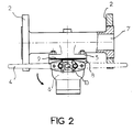
- Figure 2 is a top view.
- Figure 3 is a schematic representation in cross section of the device according to the invention.
- Figure 4 is a detail view of the method of fixing the actuating rod of the sphere.
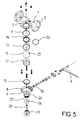
- Figure 5 is a schematic exploded view of the device according to the invention.
- FIG. 1 a schematic perspective view of the sample taking device according to the invention.
- This device consists first of all of an in-line body (1), typically consisting of a piece of pipe, capable of being fixed to such a pipe by means of flanges (2) pierced with through orifices (3 ) to allow bolting.
- the diameter of the internal pipe (7) defined by the body in line (1), is identical to that of the pipe to which it is connected.
- This in-line body (1) has an opening, communicating the inside of the pipe (7) with the outside, at a fixing zone (5) substantially formed in the middle of said body, and intended to constitute the first part of the body of a tap described in detail below.
- the whole body in line (1) / fixing area (5) comes directly from foundry and therefore constitutes a single piece.
- a fixing piece (5) To this fixing piece (5), is intended to be fixed an additional piece (6) by means of a fixing flange (8), said piece (6) constituting in fact the second part of the valve body. in question.
- a polytetrafluoroethylene (PTFE) annular seal (9) Before placing this second part on the fixing part (5), a polytetrafluoroethylene (PTFE) annular seal (9), as can best be seen in FIG. 3 or FIG. 5. In known manner, this seal is intended to impart sealing to this junction zone.
- the seal (9) can however be made of another material, such as for example graphite for an assembly of the "fire safety" type.
- the tap associated with this in-line body is a tap of the spherical ball type, the sphere (11) of which is operated by means of a lever (4) and a rod (10), is hollowed out in order to define an internal volume (12) calibrated, said sphere (11) being open at its periphery in order to define an inlet (13) capable of coming opposite the opening made at the junction zone (5), c 'that is to say with regard to the pipeline (7).
- This sphere can be made of any material, in particular sintered ceramic or metal. It is capable of operating a 180 ° rotation on itself under the combined effect of the rod (10) and the lever (4), in order to allow the contents of the volume (12) to be placed in communication. defined with a collection device (18,19,20) and a recovery bottle (21), as will be described in more detail later.
- the sphere (11) is perfectly guided within the body (5, 6) by the presence of a part of annular seats (14) and (15) reported respectively at the level of the first part (5) and second part ( 6) of the valve body, in substantially diametrical positions, and also by the installation of inserts (16) and (17), in the form of crown sectors, also received at the two constituent parts of the body, allowing in in addition to limiting the dead zone between the sphere (11) and the body of the ball valve.
- the seats and other inserts are generally made of PTFE. However, other materials can be used depending on the nature of the fluid flowing in the pipe (7).
- the downstream seat (15) is received at a shoulder (22) from foundry or machining, formed within the second part (6) constituting the body.
- this shoulder has a diameter less than the outer diameter of the sphere (11), and is likely to come into contact with said sphere (11) in the event of deterioration of the seat (15), in particular in the event of destruction by fire.
- the upstream seat (14) can be of the piston type. It has a groove intended to receive an O-ring (30) made of elastomer resistant to the fluids to be sampled.
- the assembly thus produced constitutes a piston which is permanently pressed against the sphere (11) by the pressure of the fluid.
- This system thus makes it possible to significantly reduce the operating torque by very significantly reducing the friction forces of the sphere (11) on the upstream seat (14), while ensuring total sealing between the seats (14) and (15) and the sphere (11) throughout the duration of the sample collection maneuver (rotation of the sphere by 180 degrees).
- the device comprises a receptacle for collecting the liquid thus withdrawn.
- This receptacle or bottle (21) is removably attached to an adapter endpiece (19) having a thread corresponding to the external thread formed on the neck of said receptacle (21).
- This same adapter end piece (19) tightens an outlet tube (20) and a collection ring (18), the assembly being held at the level of the second part (6) constituting the body. of the tap by screwing said adapter end piece on an internal thread (27) formed for this purpose on the part (26) that this said second part comprises, as can be seen in FIG. 5.
- these are generally made of PTFE loaded with glass fibers. Other materials can be used depending on the nature of the fluid to be sampled.
- the seal, and more particularly the "security - fire” system developed by the device is also imparted at the level of the rod (10) and of the lever (4) actuating the sphere (11). .
- this rod (10) drives the sphere (11) by means of a groove (25) formed on its periphery, by means of a tenon (24) coming to be housed in said groove, said rod being mounted at the part (6) constituting the valve body with a seal, consisting of a stack of several rings (23) machined in the form of chevrons, thus allowing a deformation of the lining, by tightening the cable gland (29).
- This lining is generally made of PTFE.
- the packing (23) consists of rings made of graphite as well as the seal between the two parts of the body (9).
- the assembly is given a total seal with respect to the outside throughout the duration of the maneuver, this which is essential in all processes, especially in the chemical and petrochemical industry.
Abstract
Description
L'invention concerne un nouveau dispositif de prise d'échantillon, notamment fluide et plus particulièrement liquide sur une canalisation.The invention relates to a new device for taking samples, in particular fluid and more particularly liquid on a pipe.
Lors de nombreux procédés de fabrication ou de synthèse dans différentes industries, notamment la chimie, la pétrochimie, la pharmacie, l'agro-alimentaire, il s'avère nécessaire de procéder à un ou plusieurs contrôles de la qualité du produit en cours de fabrication ou d'élaboration lors des différentes étapes du procédé en cause et ce, afin notamment d'aboutir à un produit répondant aux normes qualitatives requises, et ainsi d'éviter les rebuts en influant, en fonction des analyses effectuées, sur les paramètres et les conditions mis en oeuvre lors dudit procédé.During many manufacturing or synthesis processes in different industries, notably chemistry, petrochemistry, pharmacy, food industry, it is necessary to carry out one or more quality controls of the product during manufacture or developed during the various stages of the process in question, in particular in order to achieve a product that meets the required quality standards, and thus avoid waste by influencing, depending on the analyzes carried out, the parameters and conditions implemented during said process.
Pour ce faire, il est généralement installé au niveau des canalisations de transfert des produits des robinets classiques permettant manuellement de collecter lesdits produits afin de procéder à leur analyse. Outre le fait qu'avec un tel robinet, l'opérateur entre en contact direct avec le fluide à analyser ou ses émanations, qui peuvent être toxiques, la quantité de liquide prélevé est totalement aléatoire, et de plus, l'étanchéité de ce type de robinet est souvent insuffisante pour un grand nombre d'applications.To do this, it is generally installed at the level of the product transfer pipes of conventional taps allowing manual collection of said products in order to carry out their analysis. Besides the fact that with such a tap, the operator comes into direct contact with the fluid to be analyzed or its fumes, which can be toxic, the quantity of liquid sampled is completely random, and moreover, this type of tightness is often insufficient for a large number of applications.
Il existe des systèmes de prélèvement d'échantillons à clapet ou pointeau, montés sur une dérivation par rapport à la canalisation principale, qui permettent alors le remplissage d'un flacon. L'organe d'étanchéité du robinet est constitué d'un clapet, d'un pointeau ou d'un cylindre ; l'ouverture s'effectue soit directement dans la veine fluide, soit dans le corps du robinet, par l'intermédiaire d'un volant qui dégage l'organe d'étanchéité de son siège, et laisse écouler le liquide dans le flacon.There are valve or needle sampling systems, mounted on a bypass with respect to the main pipe, which then allow the filling of a bottle. The sealing member of the tap consists of a valve, a needle or a cylinder; the opening is carried out either directly in the fluid stream, or in the body of the tap, via a flywheel which releases the sealing member from its seat, and lets the liquid flow into the bottle.
Ce système présente certains inconvénients. Il est en effet nécessaire d'avoir une bonne étanchéité au passage de la tige de commande (presse-étoupe) et du siège. Or cette étanchéité est relativement difficile à obtenir avec des fluides agressifs chimiquement et/ou chargés. En outre, elle s'altère de plus en plus au fur et à mesure de l'augmentation du nombre de manoeuvres. Enfin, le flacon est soumis à la même pression que celle de la conduite principale.This system has certain drawbacks. It is indeed necessary to have a good seal at the passage of the control rod (cable gland) and the seat. However, this seal is relatively difficult to obtain with chemically aggressive and / or charged fluids. In addition, it deteriorates more and more as the number of operations increases. Finally, the bottle is subjected to the same pressure as that of the main line.
Enfin, il est également proposé un dispositif mettant en oeuvre un système d'aiguilles, constitué d'une vanne, d'une fixation d'aiguilles et d'une manchette de protection. Deux aiguilles assurent, l'une le prélèvement, et l'autre l'échappement. Un tel système est monté sur la conduite par les raccordements de la vanne. Cependant, si ce dispositif permet un prélèvement d'une quantité déterminée de produit à analyser, en revanche, ledit produit ne peut être qu'excessivement propre et de très faible viscosité, compte tenu de la mise en oeuvre d'aiguilles, dont l'orifice d'écoulement est très étroit, réduisant de fait drastiquement ses applications. De plus, il est nécessaire d'utiliser un flacon pourvu d'un diaphragme adapté à chaque produit, pour garantir une bonne étanchéité.Finally, a device is also proposed which implements a system of needles, consisting of a valve, a fixing of needles and a protective sleeve. Two needles ensure, one the sampling, and the other the exhaust. Such a system is mounted on the pipe by the valve connections. However, if this device allows a sample of a determined quantity of product to be sampled, on the other hand, said product can only be excessively clean and of very low viscosity, taking into account the use of needles, the flow hole is very narrow, drastically reducing its applications. In addition, it is necessary to use a bottle provided with a diaphragm adapted to each product, to guarantee a good seal.
La présente invention propose un dispositif de prélèvement d'échantillon sur une canalisation qui soit à la fois fiable, simple à mettre en oeuvre, qui permette de prélever des quantités calibrées du produit. Afin de conférer à l'installation générale au niveau de laquelle il est mis en place, ce dispositif est conçu selon le type "sécurité feu".The present invention provides a sample collection device on a pipe which is both reliable, simple to implement, which allows to sample calibrated quantities of the product. In order to give the general installation at the level of which it is set up, this device is designed according to the "fire safety" type.
Ce dispositif comprend :
- un corps en ligne, susceptible d'être installé sur la canalisation dans laquelle doit être prélevé l'échantillon de produit, et d'être fixé à celle-ci au moyen de brides normalisées (vissées ou monobloc), le diamètre interne du corps étant identique au diamètre interne de ladite canalisation, le corps présentant en outre une ouverture latérale, permettant la fixation d'un robinet à tournant sphérique ;
- un robinet de type à tournant sphérique, débouchant au niveau du corps en ligne par le biais de ladite ouverture latérale, constituant l'une des deux parties du corps constituant le robinet, dont l'autre partie est solidarisée à la première après mise en place d'un joint annulaire, ledit robinet comprenant une sphère évidée munie d'un trou borgne, accessible par une seule entrée, définissant ainsi un volume calibré, ladite sphère étant susceptible de pivoter de 180 degrés entre deux joints annulaires, respectivement positionnés à la jonction entre le corps en ligne et la partie amont du robinet à tournant sphérique, et au sein du corps dudit robinet à tournant sphérique, ladite sphère étant ainsi susceptible de communiquer d'une part avec le corps en ligne, au niveau de l'ouverture latérale, et d'autre part avec la partie aval du robinet, ladite partie aval comportant un canal d'écoulement vers un flacon rapporté de manière amovible sur le corps du robinet, chacune des deux parties recevant un siège de forme sensiblement annulaire, destinés à assurer l'étanchéité du robinet vis à vis de la canalisation au niveau de laquelle est effectué le prélèvement, le profil interne de la seconde partie présentant un épaulement destiné à recevoir l'un des deux sièges, dont le diamètre est inférieur au diamètre externe de la sphère, de sorte qu'en cas de destruction des sièges, un contact métal/métal ou céramique/métal est assuré afin de conférer à l'ensemble une étanchéité.
- an in-line body, capable of being installed on the pipe from which the product sample is to be taken, and of being fixed to the latter by means of standardized flanges (screwed or monobloc), the internal diameter of the body being identical to the internal diameter of said pipe, the body further having a lateral opening, allowing the fixing of a ball valve;
- a ball-type valve, opening at the level of the body in line through said lateral opening, constituting one of the two parts of the body constituting the valve, the other part of which is secured to the first after installation an annular seal, said valve comprising a hollowed-out sphere provided with a blind hole, accessible by a single entry, thus defining a calibrated volume, said sphere being capable of pivoting 180 degrees between two annular seals, respectively positioned at the junction between the body in line and the upstream part of the ball valve, and within the body of said ball valve, said sphere being thus capable of communicating on the one hand with the body in line, at the lateral opening , and on the other hand with the downstream part of the tap, said downstream part comprising a flow channel towards a bottle removably attached to the body of the tap, each of the two parts receiving a seat of substantially annular shape, intended to seal the valve opposite of the pipe at the level of which the sampling is carried out, the internal profile of the second part having a shoulder intended to receive one of the two seats, the diameter of which is less than the external diameter of the sphere, so that in the event destruction of the seats, a metal / metal or ceramic / metal contact is ensured in order to give the assembly a seal.
En d'autres termes, l'invention consiste à mettre en place outre un robinet à tournant sphérique, dont la sphère est évidée mais borgne, de telle sorte à définir un volume calibré, également des siège de forme appropriée et des éléments constitutifs du corps du robinet réalisés de façon telle, qu'en cas de feu susceptible d'entraîner la destruction desdits sièges, il se crée un contact intime entre la sphère et lesdits éléments, suffisant pour assurer l'étanchéité au feu au niveau du reste de l'installation, en d'autres termes de conférer la "sécurité - feu", ainsi que cela apparaîtra par ailleurs plus en détail ultérieurement, ce qu'il n'était pas possible d'obtenir avec les dispositifs disponibles jusqu'alors.In other words, the invention consists in putting in place in addition to a ball valve, the sphere of which is hollowed out but blind, so as to define a calibrated volume, also seats of appropriate shape and constituent elements of the body. of the tap made in such a way that in the event of a fire liable to destroy said seats, an intimate contact is created between the sphere and said elements, sufficient to ensure fire-tightness at the level of the rest of the installation, in other words to confer "fire safety", as will also appear in more detail later, which it was not possible to obtain with the devices available until then.
Selon l'invention, le corps du robinet à tournant sphérique reçoit deux inserts complémentaires en forme de couronne annulaire, destinés à remplir la cavité du corps autour de la sphère et réduire ainsi au maximum la possibilité d'introduction du fluide autour de ladite sphère, lors de la manoeuvre d'échantillonnage.According to the invention, the body of the ball valve receives two complementary inserts in the form of an annular crown, intended to fill the body cavity around the sphere and thus minimize the possibility of introduction of the fluid around said sphere, during the sampling maneuver.
Les sièges, les inserts et le joint annulaire mentionnés précédemment, sont généralement réalisés en polytétrafluoroéthylène - PTFE (TEFLON - marque déposée). Cependant, d'autres matériaux peuvent être utilisés en fonction du fluide à échantillonner.The seats, inserts and the annular seal mentioned above are generally made of polytetrafluoroethylene - PTFE (TEFLON - registered trademark). However, other materials can be used depending on the fluid to be sampled.
Selon l'invention, le levier de manoeuvre du robinet est solidaire d'une tige. Celle-ci est épaulée et montée par l'intérieur du corps du robinet, afin d'éviter son éjection accidentelle.According to the invention, the valve operating lever is integral with a rod. It is shouldered and mounted by the inside of the valve body, in order to avoid its accidental ejection.
Le flacon de collecte des prélèvements est généralement vissé à un embout d'adaptation du flacon, lui-même solidarisé au corps du robinet à tournant sphérique, recevant en outre une bague de collecte. L'ensemble étant ainsi positionné de manière opposée par rapport à l'ouverture communiquant avec l'intérieur du corps en ligne.The sample collection bottle is generally screwed to an adapter for the bottle, itself secured to the body of the ball valve, also receiving a collection ring. The assembly is thus positioned opposite to the opening communicating with the interior of the body in line.
Le flacon peut être solidarisé au corps du robinet par filetage ou tout autre moyen d'accouplement rapide, tel que raccord à cames, à brides, ou un système bien connu sous l'expression en langue anglaise "clamps".The bottle can be secured to the body of the tap by thread or any other quick coupling means, such as cam or flange connection, or a system well known under the expression in English "clamps".
La manière dont l'invention peut être réalisée et les avantages qui en découlent, ressortiront mieux de l'exemple de réalisation qui suit donné à titre indicatif mais non limitatif, à l'appui des figures annexées.The manner in which the invention can be implemented and the advantages which ensue therefrom will emerge more clearly from the example of embodiment which follows, given by way of indication but not limitation, in support of the appended figures.
La figure 1 est une représentation schématique en perspective du dispositif conforme à l'invention, dont la figure 2 est une vue de dessus.Figure 1 is a schematic perspective representation of the device according to the invention, Figure 2 is a top view.
La figure 3 est une représentation schématique en section transversale du dispositif conforme à l'invention.Figure 3 is a schematic representation in cross section of the device according to the invention.
La figure 4 est une vue de détail du mode de fixation de la tige d'actionnement de la sphère.Figure 4 is a detail view of the method of fixing the actuating rod of the sphere.
La figure 5 est une représentation schématique en éclaté du dispositif conforme à l'invention.Figure 5 is a schematic exploded view of the device according to the invention.
On a représenté sur la figure 1 une vue schématique en perspective du dispositif de prise d'échantillon conforme à l'invention. Ce dispositif est tout d'abord constitué d'un corps en ligne (1), typiquement constitué d'un morceau de canalisation, susceptible d'être fixé à une telle canalisation au moyen de brides (2) percées d'orifices traversants (3) afin de permettre le boulonnage. Le diamètre de la canalisation interne (7) que définit le corps en ligne (1), est identique à celui de la canalisation à laquelle il est relié.There is shown in Figure 1 a schematic perspective view of the sample taking device according to the invention. This device consists first of all of an in-line body (1), typically consisting of a piece of pipe, capable of being fixed to such a pipe by means of flanges (2) pierced with through orifices (3 ) to allow bolting. The diameter of the internal pipe (7) defined by the body in line (1), is identical to that of the pipe to which it is connected.
Ce corps en ligne (1) comporte une ouverture, faisant communiquer l'intérieur de la canalisation (7) avec l'extérieur, au niveau d'une zone de fixation (5) sensiblement ménagée au milieu dudit corps, et destinée à constituer la première partie du corps d'un robinet décrit en détail ci-après. L'ensemble corps en ligne (1)/ zone de fixation (5) est directement issu de fonderie et donc constitue une pièce monobloc.This in-line body (1) has an opening, communicating the inside of the pipe (7) with the outside, at a fixing zone (5) substantially formed in the middle of said body, and intended to constitute the first part of the body of a tap described in detail below. The whole body in line (1) / fixing area (5) comes directly from foundry and therefore constitutes a single piece.
A cette pièce de fixation (5), est destinée à venir se fixer une pièce complémentaire (6) par l'intermédiaire d'une bride de fixation (8), ladite pièce (6) constituant de fait la seconde partie du corps du robinet en question. Préalablement, à la mise en place de cette seconde partie sur la partie de fixation (5), on intercale un joint annulaire en polytétrafluoroéthylène (PTFE) (9), tel qu'on peut mieux l'observer sur la figure 3 ou la figure 5. De manière connue, ce joint est destiné à conférer l'étanchéité à cette zone de jonction. Le joint (9) peut cependant être réalisé en un autre matériau, tel que par exemple en graphite pour un ensemble de type "sécurité-feu".To this fixing piece (5), is intended to be fixed an additional piece (6) by means of a fixing flange (8), said piece (6) constituting in fact the second part of the valve body. in question. Before placing this second part on the fixing part (5), a polytetrafluoroethylene (PTFE) annular seal (9), as can best be seen in FIG. 3 or FIG. 5. In known manner, this seal is intended to impart sealing to this junction zone. The seal (9) can however be made of another material, such as for example graphite for an assembly of the "fire safety" type.
Le robinet associé à ce corps en ligne est un robinet du type à tournant sphérique, dont la sphère (11), manoeuvrée par l'intermédiaire d'un levier (4) et d'une tige (10), est évidée afin de définir un volume interne (12) calibré, ladite sphère (11) étant ouverte au niveau de sa périphérie afin de définir une entrée (13) susceptible de venir en regard de l'ouverture pratiquée au niveau de la zone de jonction (5), c'est-à-dire au regard de la canalisation (7). Cette sphère peut être réalisée en tout matériau, notamment en céramique frittée ou en métal. Elle est susceptible d'opérer une rotation sur elle-même de 180° sous l'effet combiné de la tige (10) et du levier (4), afin de permettre la mise en communication du contenu du volume (12) qu'elle définit avec un dispositif de collecte (18,19,20) et un flacon de récupération (21), tel qu'il sera décrit plus en détail ultérieurement.The tap associated with this in-line body is a tap of the spherical ball type, the sphere (11) of which is operated by means of a lever (4) and a rod (10), is hollowed out in order to define an internal volume (12) calibrated, said sphere (11) being open at its periphery in order to define an inlet (13) capable of coming opposite the opening made at the junction zone (5), c 'that is to say with regard to the pipeline (7). This sphere can be made of any material, in particular sintered ceramic or metal. It is capable of operating a 180 ° rotation on itself under the combined effect of the rod (10) and the lever (4), in order to allow the contents of the volume (12) to be placed in communication. defined with a collection device (18,19,20) and a recovery bottle (21), as will be described in more detail later.
La sphère (11) est parfaitement guidée au sein du corps (5, 6) de par la présence d'une part de sièges annulaires (14) et (15) rapportés respectivement au niveau de la première partie (5) et seconde partie (6) du corps du robinet, en positions sensiblement diamétrales, et également par la mise en place d'inserts (16) et (17), en forme de secteurs de couronne, également reçus au niveau des deux parties constitutives du corps, permettant en outre de limiter la zone morte comprise entre la sphère (11) et le corps du robinet à tournant sphérique.The sphere (11) is perfectly guided within the body (5, 6) by the presence of a part of annular seats (14) and (15) reported respectively at the level of the first part (5) and second part ( 6) of the valve body, in substantially diametrical positions, and also by the installation of inserts (16) and (17), in the form of crown sectors, also received at the two constituent parts of the body, allowing in in addition to limiting the dead zone between the sphere (11) and the body of the ball valve.
Les sièges et autres inserts sont généralement réalisés en PTFE. Cependant, d'autres matériaux peuvent être utilisés selon la nature du fluide s'écoulant dans la canalisation (7).The seats and other inserts are generally made of PTFE. However, other materials can be used depending on the nature of the fluid flowing in the pipe (7).
Selon l'invention, le siège aval (15) est reçu au niveau d'un épaulement (22) issu de fonderie ou d'usinage, ménagé au sein de la seconde partie (6) constitutive du corps. Ainsi qu'on peut bien l'observer sur la figure 3, cet épaulement est de diamètre inférieur au diamètre externe de la sphère (11), et est susceptible d'entrer en contact avec ladite sphère (11) en cas de détérioration du siège (15), notamment en cas de destruction par le feu. On aboutit ainsi à un contact métal/métal ou métal/céramique si la sphère (11) est réalisée en céramique, présentant une certaine étanchéité compte tenu de la pression exercée en tout état de cause sur la sphère par le fluide circulant dans la canalisation (7), cette pression s'exerçant en direction du récipient (21). De la sorte, on aboutit à un dispositif de prélèvement d'échantillon dit "sécurité - feu".According to the invention, the downstream seat (15) is received at a shoulder (22) from foundry or machining, formed within the second part (6) constituting the body. As can be seen in Figure 3, this shoulder has a diameter less than the outer diameter of the sphere (11), and is likely to come into contact with said sphere (11) in the event of deterioration of the seat (15), in particular in the event of destruction by fire. This results in a metal / metal or metal / ceramic contact if the sphere (11) is made of ceramic, having a certain tightness taking into account the pressure exerted in any event on the sphere by the fluid circulating in the pipe (7), this pressure being exerted in the direction of the container ( 21). In this way, we end up with a sample collection device called "fire safety".
Le siège amont (14) peut être du type piston. Il comporte une gorge destinée à recevoir un joint torique (30) en élastomère résistant aux fluides à prélever. L'ensemble ainsi réalisé constitue un piston qui est appuyé en permanence contre la sphère (11) par la pression du fluide.The upstream seat (14) can be of the piston type. It has a groove intended to receive an O-ring (30) made of elastomer resistant to the fluids to be sampled. The assembly thus produced constitutes a piston which is permanently pressed against the sphere (11) by the pressure of the fluid.
Ce système permet ainsi de réduire notablement le couple de manoeuvre en diminuant très sensiblement les forces de frottement de la sphère (11) sur le siège amont (14), tout en assurant l'étanchéité totale entre les sièges (14) et (15) et la sphère (11) pendant toute la durée de la manoeuvre de prélèvement des échantillons (rotation de la sphère de 180 degrés).This system thus makes it possible to significantly reduce the operating torque by very significantly reducing the friction forces of the sphere (11) on the upstream seat (14), while ensuring total sealing between the seats (14) and (15) and the sphere (11) throughout the duration of the sample collection maneuver (rotation of the sphere by 180 degrees).
Selon l'invention, le dispositif comporte un réceptacle de collecte du liquide ainsi prélevé. Ce réceptacle ou flacon (21) est fixé de manière amovible sur un embout d'adaptation (19) présentant un taraudage correspondant au filetage externe ménagé sur le col dudit réceptacle (21). Ce même embout d'adaptation (19) assure le serrage d'un tube de sortie (20), et d'une bague de collecte (18), l'ensemble étant maintenu au niveau de la seconde partie (6) constitutive du corps du robinet par vissage dudit embout d'adaptation sur un filetage interne (27) ménagé à cet effet sur la partie (26) que comporte cette dite seconde partie ainsi qu'on peut bien l'observer sur la figure 5.According to the invention, the device comprises a receptacle for collecting the liquid thus withdrawn. This receptacle or bottle (21) is removably attached to an adapter endpiece (19) having a thread corresponding to the external thread formed on the neck of said receptacle (21). This same adapter end piece (19) tightens an outlet tube (20) and a collection ring (18), the assembly being held at the level of the second part (6) constituting the body. of the tap by screwing said adapter end piece on an internal thread (27) formed for this purpose on the part (26) that this said second part comprises, as can be seen in FIG. 5.
Afin de conférer une certaine résistance mécanique tant à la bague de collecte (18) qu'à l'embout d'adaptation (19), ceux-ci sont généralement réalisés en PTFE chargé en fibres de verre. D'autres matériaux peuvent être utilisés selon la nature du fluide à prélever.In order to give a certain mechanical resistance to both the collection ring (18) and the adapter end piece (19), these are generally made of PTFE loaded with glass fibers. Other materials can be used depending on the nature of the fluid to be sampled.
Selon une autre caractéristique de l'invention, l'étanchéité, et plus particulièrement le système "sécurité - feu" développé par le dispositif est également conférée au niveau de la tige (10) et du levier (4) actionnant la sphère (11). Ainsi qu'on peut l'observer sur les figures 3 et 4, cette tige (10) entraîne la sphère (11) au moyen d'une rainure (25) ménagée sur sa périphérie, au moyen d'un tenon (24) venant se loger dans ladite rainure, ladite tige étant montée au niveau de la partie (6) constitutive du corps du robinet avec une garniture d'étanchéité, constituée d'un empilage de plusieurs bagues (23) usinées en forme de chevrons, permettant ainsi une déformation de la garniture, par serrage du presse-étoupe (29). Cette garniture est généralement réalisée en PTFE. Dans le cas de robinet "sécurité-feu", la garniture (23) est constituée de bagues réalisées en graphite ainsi que le joint entre les deux parties du corps (9).According to another characteristic of the invention, the seal, and more particularly the "security - fire" system developed by the device is also imparted at the level of the rod (10) and of the lever (4) actuating the sphere (11). . As can be seen in Figures 3 and 4, this rod (10) drives the sphere (11) by means of a groove (25) formed on its periphery, by means of a tenon (24) coming to be housed in said groove, said rod being mounted at the part (6) constituting the valve body with a seal, consisting of a stack of several rings (23) machined in the form of chevrons, thus allowing a deformation of the lining, by tightening the cable gland (29). This lining is generally made of PTFE. In the case of a "fire safety" tap, the packing (23) consists of rings made of graphite as well as the seal between the two parts of the body (9).
Compte tenu de la structure du dispositif conforme à l'invention, on conçoit les avantages qu'il procure. Parmi ceux-ci, on peut tout d'abord citer la possibilité de disposer à volonté d'un volume calibré de fluide. Pour ce faire, une fois le prélèvement effectué, il suffit de dévisser le flacon (21) hors de l'embout (19) et de procéder à l'analyse de son contenu, et ce, en l'absence de tout contact avec l'opérateur.Given the structure of the device according to the invention, we can see the advantages it provides. Among these, we can first cite the possibility of having at will a calibrated volume of fluid. To do this, once the sample has been taken, it suffices to unscrew the bottle (21) from the end piece (19) and to analyze its content, in the absence of any contact with the 'operator.
Par ailleurs, de par le positionnement des sièges et autres inserts assurant une rotation déterminée de la sphère du robinet à tournant sphérique, on confère à l'ensemble une étanchéité totale vis à vis de l'extérieur pendant toute la durée de la manoeuvre, ce qui s'avère indispensable dans tous les procédés, notamment dans l'industrie chimique, et pétrochimique.Furthermore, by the positioning of the seats and other inserts ensuring a determined rotation of the sphere of the ball valve, the assembly is given a total seal with respect to the outside throughout the duration of the maneuver, this which is essential in all processes, especially in the chemical and petrochemical industry.
Claims (6)
Applications Claiming Priority (2)
| Application Number | Priority Date | Filing Date | Title |
|---|---|---|---|
| FR9606175A FR2748566B1 (en) | 1996-05-10 | 1996-05-10 | SAMPLE TAKING DEVICE ON A PIPELINE |
| FR9606175 | 1996-05-10 |
Publications (1)
| Publication Number | Publication Date |
|---|---|
| EP0806648A1 true EP0806648A1 (en) | 1997-11-12 |
Family
ID=9492240
Family Applications (1)
| Application Number | Title | Priority Date | Filing Date |
|---|---|---|---|
| EP97420069A Withdrawn EP0806648A1 (en) | 1996-05-10 | 1997-04-29 | Device for taking a sample from a conduit |
Country Status (3)
| Country | Link |
|---|---|
| US (1) | US5922972A (en) |
| EP (1) | EP0806648A1 (en) |
| FR (1) | FR2748566B1 (en) |
Cited By (4)
| Publication number | Priority date | Publication date | Assignee | Title |
|---|---|---|---|---|
| DE29800967U1 (en) * | 1998-01-22 | 1998-04-16 | Westhydraulik Becker Behaelter | Sampling device for hot bitumen and related materials in binder storage and supply systems |
| WO2010121765A1 (en) * | 2009-04-22 | 2010-10-28 | Wisser Joerg | Sampling system |
| BE1025970B1 (en) * | 2018-02-01 | 2019-09-03 | R. DEZWAEF naamloze vennootschap | Apparatus for taking a fluid sample from a tube or reservoir and device equipped therewith |
| WO2023222446A1 (en) * | 2022-05-20 | 2023-11-23 | Axens | Device for sampling solid particles comprising at least one capacitive valve |
Families Citing this family (10)
| Publication number | Priority date | Publication date | Assignee | Title |
|---|---|---|---|---|
| US20030200822A1 (en) * | 2002-04-25 | 2003-10-30 | Timothy Layton | Oil field sample apparatus |
| DE102009018566B3 (en) * | 2009-04-24 | 2010-05-27 | Andocksysteme G. Untch Gmbh | Valve for taking a sample from a content of a container |
| US8397592B2 (en) * | 2010-02-19 | 2013-03-19 | Vertex Pharmaceuticals, Inc. | Systems and methods for inline sampling |
| CN102837738B (en) * | 2012-09-20 | 2015-07-08 | 湖南中联重科车桥有限公司 | Steering axle and vehicle with same |
| US11237082B2 (en) | 2013-02-27 | 2022-02-01 | Martin Atchison | Single outer tubular flow scoop for oil and gas pipelines with internal bidrectional flow |
| US9562839B2 (en) | 2013-02-27 | 2017-02-07 | Martin Atchison | Scoop assembly and method |
| US9696244B2 (en) * | 2015-06-11 | 2017-07-04 | Western Energy Support and Technology, Inc | Inline sampling for multi-phase flow |
| US10359342B2 (en) * | 2017-03-15 | 2019-07-23 | Sentry Equipment Corp. | Pipeline sampler |
| CN110608992A (en) * | 2019-10-17 | 2019-12-24 | 浙江大学 | Probe device and method for testing high-temperature corrosion resistance of metal material on heating surface of waste incineration boiler |
| CN115683730B (en) * | 2022-11-17 | 2023-10-13 | 新疆合创检测技术有限公司 | Sampling equipment for food safety detection |
Citations (8)
| Publication number | Priority date | Publication date | Assignee | Title |
|---|---|---|---|---|
| US4342444A (en) * | 1980-10-14 | 1982-08-03 | Xomox Corporation | Ball valve assembly |
| GB2140896A (en) * | 1983-06-03 | 1984-12-05 | N H Engineering Limited | Ball valve seals |
| GB2207735A (en) * | 1987-08-05 | 1989-02-08 | Blackfive Engineering Limited | Fluid control valve |
| DE3932202A1 (en) * | 1989-09-27 | 1991-04-04 | Pfeiffer Chemie Armaturen | Discontinuous sampling arrangement for product line - has blocking and dispensing element which seals product line outlet before reaching its closed position |
| US5070909A (en) * | 1990-06-11 | 1991-12-10 | Davenport Robert G | Low recovery rotary control valve |
| DE9202623U1 (en) * | 1992-02-28 | 1992-04-23 | Kernforschungszentrum Karlsruhe Gmbh, 7500 Karlsruhe, De | |
| US5305986A (en) * | 1993-03-31 | 1994-04-26 | Hunt Kevin F | Fluid control valve |
| DE9401379U1 (en) * | 1994-01-27 | 1994-11-03 | Pfeiffer Chemie Armaturen | Device for taking samples from a liquid-carrying product line of a process plant |
Family Cites Families (13)
| Publication number | Priority date | Publication date | Assignee | Title |
|---|---|---|---|---|
| US2864254A (en) * | 1956-04-23 | 1958-12-16 | U S Flexible Metallic Tubing C | Sample-taking valve |
| US3561727A (en) * | 1968-01-25 | 1971-02-09 | Domer Scaramucci | High stress valve seal and valves |
| US3617027A (en) * | 1970-07-01 | 1971-11-02 | Domer Scaramucci | Rocking seat valve |
| US3744319A (en) * | 1971-06-08 | 1973-07-10 | New Brunswick Scientific Co | Liquid-sampling structure |
| US3784155A (en) * | 1973-04-13 | 1974-01-08 | Acf Ind Inc | Ball and seat arrangement for ball valve |
| US4286614A (en) * | 1979-09-19 | 1981-09-01 | Acf Industries, Incorporated | High temperature ball valve |
| US4350052A (en) * | 1980-07-30 | 1982-09-21 | Elizabeth Virginia Kendall | Apparatus and method for tapping and extracting oil samples from an underground high pressure pipe-type transmission cable system |
| US4472977A (en) * | 1982-09-09 | 1984-09-25 | Lynn Lewis G | Fixed volume fluid sampler for pressurized process lines |
| US4671308A (en) * | 1982-10-14 | 1987-06-09 | Whitey Co. | Fire-safe ball valve |
| DD234074A1 (en) * | 1985-01-16 | 1986-03-19 | Buna Chem Werke Veb | SAMPLER FOR POLYMER MELTS |
| US4637421A (en) * | 1986-05-15 | 1987-01-20 | Stunkard Gerald A | In-line repairable top entry ball valve |
| NL9001848A (en) * | 1990-08-21 | 1992-03-16 | Oving Diepeveen Struycken B V | Valve with internal cavity for fluid sampling - has hollow valve ball and sample discharge channels for on=line sampling of fluid processing |
| US5408890A (en) * | 1992-10-08 | 1995-04-25 | Klaus; Bruno G. | Portable sampling apparatus |
-
1996
- 1996-05-10 FR FR9606175A patent/FR2748566B1/en not_active Expired - Fee Related
-
1997
- 1997-04-29 EP EP97420069A patent/EP0806648A1/en not_active Withdrawn
- 1997-05-08 US US08/853,336 patent/US5922972A/en not_active Expired - Fee Related
Patent Citations (8)
| Publication number | Priority date | Publication date | Assignee | Title |
|---|---|---|---|---|
| US4342444A (en) * | 1980-10-14 | 1982-08-03 | Xomox Corporation | Ball valve assembly |
| GB2140896A (en) * | 1983-06-03 | 1984-12-05 | N H Engineering Limited | Ball valve seals |
| GB2207735A (en) * | 1987-08-05 | 1989-02-08 | Blackfive Engineering Limited | Fluid control valve |
| DE3932202A1 (en) * | 1989-09-27 | 1991-04-04 | Pfeiffer Chemie Armaturen | Discontinuous sampling arrangement for product line - has blocking and dispensing element which seals product line outlet before reaching its closed position |
| US5070909A (en) * | 1990-06-11 | 1991-12-10 | Davenport Robert G | Low recovery rotary control valve |
| DE9202623U1 (en) * | 1992-02-28 | 1992-04-23 | Kernforschungszentrum Karlsruhe Gmbh, 7500 Karlsruhe, De | |
| US5305986A (en) * | 1993-03-31 | 1994-04-26 | Hunt Kevin F | Fluid control valve |
| DE9401379U1 (en) * | 1994-01-27 | 1994-11-03 | Pfeiffer Chemie Armaturen | Device for taking samples from a liquid-carrying product line of a process plant |
Cited By (6)
| Publication number | Priority date | Publication date | Assignee | Title |
|---|---|---|---|---|
| DE29800967U1 (en) * | 1998-01-22 | 1998-04-16 | Westhydraulik Becker Behaelter | Sampling device for hot bitumen and related materials in binder storage and supply systems |
| WO2010121765A1 (en) * | 2009-04-22 | 2010-10-28 | Wisser Joerg | Sampling system |
| EA022996B1 (en) * | 2009-04-22 | 2016-04-29 | Йорг Виссер | Sampling system |
| BE1025970B1 (en) * | 2018-02-01 | 2019-09-03 | R. DEZWAEF naamloze vennootschap | Apparatus for taking a fluid sample from a tube or reservoir and device equipped therewith |
| WO2023222446A1 (en) * | 2022-05-20 | 2023-11-23 | Axens | Device for sampling solid particles comprising at least one capacitive valve |
| FR3135783A1 (en) * | 2022-05-20 | 2023-11-24 | Axens | device for taking samples of solid particles comprising at least one capacitive valve |
Also Published As
| Publication number | Publication date |
|---|---|
| FR2748566B1 (en) | 1998-07-03 |
| US5922972A (en) | 1999-07-13 |
| FR2748566A1 (en) | 1997-11-14 |
Similar Documents
| Publication | Publication Date | Title |
|---|---|---|
| EP0806648A1 (en) | Device for taking a sample from a conduit | |
| EP0432013B1 (en) | Pipe connector fitted with a leak draining device | |
| BE1000713A4 (en) | Off valve and flow control. | |
| EP0141940A1 (en) | Device to collect samples of liquid flowing in a conduit or to inject a liquid into this conduit | |
| FR2528144A1 (en) | SEALING DEVICE FOR A SPHERICAL ROTARY TAP | |
| FR2979687A1 (en) | Connection assembly for use with e.g. gaseous hydrogen tank to fill tank, has calibrated opening whose surface area is less than that of flow passage, so that fluid flow in filling position is greater than that in removal position | |
| WO2014009279A1 (en) | Pressure-reducing valve having a residual pressure function built into the reducing valve | |
| FR2792387A1 (en) | VALVE CONNECTION FOR A PRESSURE CONTAINER | |
| WO2002038992A1 (en) | Valve with sealed bellows and packing box for container transporting toxic fluids | |
| EP0306416A1 (en) | Pilot-operated safety valve | |
| FR2470320A1 (en) | SAMPLING TAP VALVE WITH PISTON POSITION INDICATOR | |
| EP0278861B1 (en) | Control valve for gas | |
| LU85226A1 (en) | STEEL BOTTLE FOR A BEVERAGE MACHINE | |
| LU86439A1 (en) | TAP FOR COMPRESSED OR LIQUEFIED GASES | |
| EP0462139B1 (en) | Through valves with rubber bushing and hemispheric closure member | |
| EP0607770A1 (en) | Double valve arrangement | |
| FR2640353A1 (en) | Safety packaging device, particularly for transporting, storing, and dispensing gas | |
| FR2788325A1 (en) | HIGH PRESSURE VALVE | |
| FR2612600A1 (en) | Testing device for hydraulic circuits | |
| FR2636137A1 (en) | Device for taking samples of liquid products | |
| EP0271401B1 (en) | Device for emptying laboratory reactors | |
| FR2635912A1 (en) | REGENERABLE SEALED ELECTRONIC TUBE DEVICE | |
| FR2507733A1 (en) | VALVE WITH DIRECT PASSAGE | |
| FR2536823A1 (en) | Device of the magnetically-controlled valve type comprising control by a link rod. | |
| FR3098564A1 (en) | Accessory holder device cooperating with a pipe containing a fluid |
Legal Events
| Date | Code | Title | Description |
|---|---|---|---|
| PUAI | Public reference made under article 153(3) epc to a published international application that has entered the european phase |
Free format text: ORIGINAL CODE: 0009012 |
|
| AK | Designated contracting states |
Kind code of ref document: A1 Designated state(s): BE DE ES GB IT NL |
|
| 17P | Request for examination filed |
Effective date: 19980423 |
|
| 17Q | First examination report despatched |
Effective date: 20021202 |
|
| STAA | Information on the status of an ep patent application or granted ep patent |
Free format text: STATUS: THE APPLICATION IS DEEMED TO BE WITHDRAWN |
|
| 18D | Application deemed to be withdrawn |
Effective date: 20040911 |