EP0806582A2 - Kupplungsausrücklager mit einem Käfig mit axialer Arretierung - Google Patents
Kupplungsausrücklager mit einem Käfig mit axialer Arretierung Download PDFInfo
- Publication number
- EP0806582A2 EP0806582A2 EP97401019A EP97401019A EP0806582A2 EP 0806582 A2 EP0806582 A2 EP 0806582A2 EP 97401019 A EP97401019 A EP 97401019A EP 97401019 A EP97401019 A EP 97401019A EP 0806582 A2 EP0806582 A2 EP 0806582A2
- Authority
- EP
- European Patent Office
- Prior art keywords
- ring
- raceway
- balls
- cage
- bearing
- Prior art date
- Legal status (The legal status is an assumption and is not a legal conclusion. Google has not performed a legal analysis and makes no representation as to the accuracy of the status listed.)
- Withdrawn
Links
Images

Classifications
-
- F—MECHANICAL ENGINEERING; LIGHTING; HEATING; WEAPONS; BLASTING
- F16—ENGINEERING ELEMENTS AND UNITS; GENERAL MEASURES FOR PRODUCING AND MAINTAINING EFFECTIVE FUNCTIONING OF MACHINES OR INSTALLATIONS; THERMAL INSULATION IN GENERAL
- F16C—SHAFTS; FLEXIBLE SHAFTS; ELEMENTS OR CRANKSHAFT MECHANISMS; ROTARY BODIES OTHER THAN GEARING ELEMENTS; BEARINGS
- F16C33/00—Parts of bearings; Special methods for making bearings or parts thereof
- F16C33/30—Parts of ball or roller bearings
- F16C33/38—Ball cages
- F16C33/41—Ball cages comb-shaped
- F16C33/412—Massive or moulded comb cages, e.g. snap ball cages
- F16C33/414—Massive or moulded comb cages, e.g. snap ball cages formed as one-piece cages, i.e. monoblock comb cages
- F16C33/416—Massive or moulded comb cages, e.g. snap ball cages formed as one-piece cages, i.e. monoblock comb cages made from plastic, e.g. injection moulded comb cages
-
- F—MECHANICAL ENGINEERING; LIGHTING; HEATING; WEAPONS; BLASTING
- F16—ENGINEERING ELEMENTS AND UNITS; GENERAL MEASURES FOR PRODUCING AND MAINTAINING EFFECTIVE FUNCTIONING OF MACHINES OR INSTALLATIONS; THERMAL INSULATION IN GENERAL
- F16C—SHAFTS; FLEXIBLE SHAFTS; ELEMENTS OR CRANKSHAFT MECHANISMS; ROTARY BODIES OTHER THAN GEARING ELEMENTS; BEARINGS
- F16C33/00—Parts of bearings; Special methods for making bearings or parts thereof
- F16C33/30—Parts of ball or roller bearings
- F16C33/38—Ball cages
- F16C33/3806—Details of interaction of cage and race, e.g. retention, centring
-
- F—MECHANICAL ENGINEERING; LIGHTING; HEATING; WEAPONS; BLASTING
- F16—ENGINEERING ELEMENTS AND UNITS; GENERAL MEASURES FOR PRODUCING AND MAINTAINING EFFECTIVE FUNCTIONING OF MACHINES OR INSTALLATIONS; THERMAL INSULATION IN GENERAL
- F16C—SHAFTS; FLEXIBLE SHAFTS; ELEMENTS OR CRANKSHAFT MECHANISMS; ROTARY BODIES OTHER THAN GEARING ELEMENTS; BEARINGS
- F16C33/00—Parts of bearings; Special methods for making bearings or parts thereof
- F16C33/30—Parts of ball or roller bearings
- F16C33/58—Raceways; Race rings
- F16C33/583—Details of specific parts of races
- F16C33/585—Details of specific parts of races of raceways, e.g. ribs to guide the rollers
-
- F—MECHANICAL ENGINEERING; LIGHTING; HEATING; WEAPONS; BLASTING
- F16—ENGINEERING ELEMENTS AND UNITS; GENERAL MEASURES FOR PRODUCING AND MAINTAINING EFFECTIVE FUNCTIONING OF MACHINES OR INSTALLATIONS; THERMAL INSULATION IN GENERAL
- F16D—COUPLINGS FOR TRANSMITTING ROTATION; CLUTCHES; BRAKES
- F16D23/00—Details of mechanically-actuated clutches not specific for one distinct type
- F16D23/12—Mechanical clutch-actuating mechanisms arranged outside the clutch as such
- F16D23/14—Clutch-actuating sleeves or bearings; Actuating members directly connected to clutch-actuating sleeves or bearings
- F16D23/142—Clutch-actuating sleeves or bearings; Actuating members directly connected to clutch-actuating sleeves or bearings with a resilient member acting radially between the bearing and its guide means
-
- F—MECHANICAL ENGINEERING; LIGHTING; HEATING; WEAPONS; BLASTING
- F16—ENGINEERING ELEMENTS AND UNITS; GENERAL MEASURES FOR PRODUCING AND MAINTAINING EFFECTIVE FUNCTIONING OF MACHINES OR INSTALLATIONS; THERMAL INSULATION IN GENERAL
- F16C—SHAFTS; FLEXIBLE SHAFTS; ELEMENTS OR CRANKSHAFT MECHANISMS; ROTARY BODIES OTHER THAN GEARING ELEMENTS; BEARINGS
- F16C19/00—Bearings with rolling contact, for exclusively rotary movement
- F16C19/02—Bearings with rolling contact, for exclusively rotary movement with bearing balls essentially of the same size in one or more circular rows
- F16C19/14—Bearings with rolling contact, for exclusively rotary movement with bearing balls essentially of the same size in one or more circular rows for both radial and axial load
- F16C19/16—Bearings with rolling contact, for exclusively rotary movement with bearing balls essentially of the same size in one or more circular rows for both radial and axial load with a single row of balls
- F16C19/163—Bearings with rolling contact, for exclusively rotary movement with bearing balls essentially of the same size in one or more circular rows for both radial and axial load with a single row of balls with angular contact
-
- F—MECHANICAL ENGINEERING; LIGHTING; HEATING; WEAPONS; BLASTING
- F16—ENGINEERING ELEMENTS AND UNITS; GENERAL MEASURES FOR PRODUCING AND MAINTAINING EFFECTIVE FUNCTIONING OF MACHINES OR INSTALLATIONS; THERMAL INSULATION IN GENERAL
- F16C—SHAFTS; FLEXIBLE SHAFTS; ELEMENTS OR CRANKSHAFT MECHANISMS; ROTARY BODIES OTHER THAN GEARING ELEMENTS; BEARINGS
- F16C2361/00—Apparatus or articles in engineering in general
- F16C2361/43—Clutches, e.g. disengaging bearing
-
- F—MECHANICAL ENGINEERING; LIGHTING; HEATING; WEAPONS; BLASTING
- F16—ENGINEERING ELEMENTS AND UNITS; GENERAL MEASURES FOR PRODUCING AND MAINTAINING EFFECTIVE FUNCTIONING OF MACHINES OR INSTALLATIONS; THERMAL INSULATION IN GENERAL
- F16C—SHAFTS; FLEXIBLE SHAFTS; ELEMENTS OR CRANKSHAFT MECHANISMS; ROTARY BODIES OTHER THAN GEARING ELEMENTS; BEARINGS
- F16C33/00—Parts of bearings; Special methods for making bearings or parts thereof
- F16C33/30—Parts of ball or roller bearings
- F16C33/58—Raceways; Race rings
- F16C33/588—Races of sheet metal
Definitions
- the present invention relates to the field of bearings and more particularly clutch bearing bearings comprising a rotating ring and a non-rotating ring, made of pressed sheet metal, each ring comprising a circular raceway having the shape of a portion of toroid , said path having in axial section a profile in a concave arc, and balls arranged between the raceways of the two rings and maintained at regular circumferential spacing by a plastic cage.
- clutch thrust bearings the non-rotating inner ring of which is provided with a circular raceway having in the meridian axial section a profile in a concave arc of a circle and the main part of which extends axially. on one side of the radial plane defined by the center of the balls extends on the other side of said radial plane to form a step.
- the row of balls held by the cage is then placed on the raceway of the inner ring, then the outer ring is placed around the row of balls and a seal is mounted on the outer ring.
- This type of bearing presents, however, some disadvantages.
- the raceway with step of the inner ring cannot be obtained directly by stamping, heat treatment and additional lapping but by stamping, heat treatment, then grinding and lapping, which complicates manufacture and increases the cost of the part.
- stamping, heat treatment, then grinding and lapping which complicates manufacture and increases the cost of the part.
- the handling of inner ring, cage and ball assemblies is always tricky because the balls are particularly exposed to shocks, pollution by foreign bodies and risks of disengaging the cells of the cage.
- the small residual axial space between the outer ring and the support flange of the inner ring requires use a sealing member placed on the inner ring before the assembly of the cage and ball assembly, said sealing member being then crimped forward on the outer ring once the latter is positioned on the marbles.
- the assembly is therefore relatively complex and the seals used in this case are expensive.
- the object of the present invention is to remedy the aforementioned drawbacks by proposing a bearing, the inner and outer rings of which are secured without requiring additional grinding operations, and a clutch stop equipped with such a bearing.
- the invention also relates to a thrust bearing which can be mounted in a sub-assembly comprising the outer ring, the row of balls held by the cage and the seal so as to fix the seal. on the outer ring before mounting the inner ring.
- the bearing according to the invention is in particular intended to equip a clutch bearing and is of the type comprising an inner ring and an outer ring, made of sheet metal, each ring comprising a circular raceway having the shape of a torus portion, said raceway having an axial meridian section a profile in a concave arc of a circle, a row of balls held by a holding cage and arranged between the raceway a first ring which forms an axial stop for the balls in a first direction, and the raceway of a second ring which forms an axial stop for the balls in a second direction, and a sealing member fixed to the second ring , and comprising means for axially retaining the balls and their holding cage relative to the second ring in the first direction.
- the rolling element holding cage comprises means forming an axial stop in the second direction and cooperating with a rim secured to the first ring, the raceway of one of the rings being located axially on one side of the plane passing through the center of the balls, while the raceway of the other ring is located axially on the other side of said plane.
- the first ring comprises a cylindrical surface provided with an annular groove with at least one radial edge capable of cooperating with the means forming a stop.
- the ball retaining cage comprises a stop portion projecting radially in the groove of the first ring.
- the abutment portion may include a row of lugs or a radially flexible circular lip.
- the abutment portion comprises a front surface intended to cooperate with a radial edge of the groove, as well as an oblique surface intended to facilitate the mounting of the support cage on the first ring.
- the ball retaining cage comprising cells for the balls, the stop means are arranged between the cells.
- the means forming a stop are arranged on the side of the sealing member.
- the stop means are arranged on the side opposite to the sealing member.
- the raceway of one of the rings is located axially on one side of the plane passing through the center of the balls and the raceway of the other ring is located axially on the other side of said plane.
- the invention also relates to a clutch stop equipped with such a bearing and comprising a guide sleeve having a radial surface coming into friction contact with a radial part of the non-rotating ring and a cylindrical surface cooperating with means elastic self-alignment of the bearing.
- a sub-assembly is made up comprising the outer ring, the row of balls held by their cage and the sealing member fixed to the outer ring, and the inner ring is brought in by an axial movement, the balls coming into contact with the raceway of said inner ring and the means forming an axial stop for the cage coming to cooperate with the rim of said inner ring.
- the inner bearing ring is manufactured as follows: at least one raceway intended to cooperate with balls and forming an axial stop for said balls in one direction is formed by stamping from a sheet metal blank, a cylindrical seat adjacent to the raceway so that the radial plane separating the raceway and the cylindrical portion passes through the center of the balls, and an annular groove whose edge opposite the raceway is substantially radial, then the ring is heat treated and we run the raceway.
- the inner ring can be produced by a simple manufacturing process, not requiring the formation of a raceway provided with a step, thereby eliminating the need for a grinding operation for the machining of said step.
- sub-assemblies comprising the outer ring, the cage and the row of rolling elements which allows better protection of rolling elements by reducing the risk of damage and loss of balls. This facilitates the automation of the assembly process.
- the clutch thrust bearing comprises a thin-walled inner bearing ring 1 produced by stamping a sheet or tube having a portion-shaped circular raceway torus 2 for a row of balls 3, said path having in axial meridian section a profile in a concave arc.
- the inner ring 1 has a radial portion 4 directed outwards.
- the rolling bearing is completed by an outer ring 5 having a radial portion 6 projecting towards the outside of the assembly and which is capable of coming into contact with the surface of a diaphragm 7 or of an equivalent element allowing the actuation of a clutch, for example of a motor vehicle.
- the outer ring 5 also has a thin wall and can be produced by stamping a sheet or tube.
- the outer ring 5 has a circular raceway 5b in the form of a torus portion for the row of balls 3, said race having in axial meridian section a profile in a concave arc.
- the balls 3 are held by a cage 8 between the raceway 2 of the inner ring 1 and that 5b of the outer ring 5.
- the ball bearing is completed by a protective cover 9 sealingly mounted on a cylindrical branch 5a of the outer ring 5 opposite the radial portion 6.
- the inner portion of the inner ring 1 comprises an elastic piece 10 having a plurality of ribs 11 oriented radially or slightly inclined relative to a radial direction and capable of bending in order to allow the self-alignment of the stop.
- a rigid guide sleeve referenced 12 as a whole serves as a support for the aforementioned ball bearing by means of the ribs 11.
- the guide sleeve 12 has a cylindrical part in the form of a sleeve 13 on the external cylindrical surface of which the ribs 11 come in contact.
- the sleeve 13 is made of synthetic material.
- the sleeve 12 further comprises at the end of the sleeve 13 a radial support portion 14 made of thin sheet metal on which the sleeve 13 is overmolded.
- the radial support portion 14 comprises two opposite radial surfaces 14a and 14b.
- a clutch release fork 15 comes into contact with the radial surface 14b of the radial support portion 14 and is capable of controlling the axial movement of the clutch stop.
- the radial portion 4 directed towards the outside of the inner ring 1 is in frictional contact with the radial surface 14a of the radial support portion 14.
- the ball bearing constituted by the two rings 1 and 5 and the balls 3 can move in a radial plane relative to the rigid sleeve 12, the elastic ribs 11 more or less crushing and this movement in a radial plane being guided by the friction contact between the radial branch 4 and the surface 14a of the radial portion 14.
- the control fork 15 comes to bear on the radial surface 14b, made of treated steel and opposite to the radial surface 14a of the radial bearing portion 14.
- the inner ring 1 comprises a cylindrical bearing surface 16 adjacent to the raceway 2 of the balls 3. On this cylindrical bearing surface 16 is provided an annular groove 17 whose edge 18 on the side opposite the balls 3 is substantially radial.
- the cage 8 comprises cells 19 in which the balls 3 are arranged, spacing portions 20 arranged circumferentially between the cells 19 and an annular portion 21 disposed between the balls 3 and the radial portion 6 of the outer ring 5.
- the portion annular 21 comprises a cylindrical surface 21a facing the groove 17 of the inner ring 1.
- retaining lugs 22 which project into the groove 17 of the inner ring 1.
- the retaining lugs 22 comprise an oblique surface 22a as well as a front surface 22b.
- the oblique surface 22a facilitates the mounting of the cage 8 equipped with the balls 3 on the inner ring 1, the lugs 22 can easily bend outwards then resume their initial shape in the groove 17.
- the front surface 22b can come into axial contact against the radial edge 18 of the groove 17 and thus form a stop preventing the cage 8 and the balls 3 from detaching from the inner ring 1.
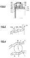
- FIG. 2 and 3 illustrate a bearing according to the prior art.
- the references of elements similar to those of FIG. 1 have been increased by the number 100.
- the clutch thrust bearing comprises an inner ring 101 provided with a circular raceway 102 in the form of a torus portion for balls 103 and a portion 104 extending radially outward.
- the bearing also includes an outer ring 105 having a portion 106 extending radially inward.
- the balls 103 are held by a cage 108.
- the outer ring supports a seal 109 capable of axially securing said outer ring 105 and the row of balls 103.
- the inner ring 101 is mounted on elastic self-alignment means 110, 111 relative to a guide sleeve 112 which comprises a cylindrical portion 113 and a radial support flange 114 in axial contact with the radial portion 104 of the inner ring 101.
- the radius R of the concave profile of the raceways although very close to the value of the radius of the balls, is chosen very slightly greater than said radius of the balls so that the theoretical contact between a ball and the raceways made at two diametrically opposite points and along a line of contact making an angle with respect to a radial plane passing through the center of the balls.
- the main part 102a of the circular raceway 102 is axially on one side of the radial plane passing through the center of the balls.
- the circular raceway 102 also extends on the other side of the radial plane, and over a small axial distance, so as to define a step 101a whose diameter is greater than that 102b of the bottom of the groove formed by the raceway. bearing 102.
- Such an inner ring 101 is obtained by stamping, heat treatment, rectification with removal of chips to form the profile of the circular raceway 102 comprising the step 101a then lapping. Once placed in the raceway 102, the balls 103 held by the cage 108 cannot be detached from the inner ring 101 because they are retained by said step 101a.
- the raceway 2 of the inner ring has no step and is adjacent to the cylindrical bearing 16.
- the profile of raceway 2 can therefore be obtained directly by stamping and does not require no rectification operation for the formation of the step.
- the raceway 2 of the inner ring 1 is located in its entirety axially on one side of the plane which passes through the center of the balls 3 while the raceway 5b of the outer ring 5 is located in its entirety axially from the on the other side of the same plane.
- the balls 3 are thus in axial abutment in a first direction against the inner ring and in axial abutment in a second direction against the outer ring 5.
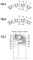
- the cage 8 for holding the rolling elements comprises spacing portions 20 which separate the cells 19 provided for receiving the rolling elements.
- On the bore 21a of the annular portion 21 is provided a plurality of radial lugs 22 capable of cooperating with a flange of an inner ring.
- the cage 8 illustrated in Figure 6 is similar to that of Figure 5 except that the lugs are replaced by a discontinuous annular lip 23 whose function is identical to that of the lugs.
- the annular lip 23 provides a firmer stop than the pins while retaining a certain flexibility for assembly.
- the thrust bearing comprises a rotating inner ring 51 comprising a raceway 52 for the rolling elements 53 and a portion 54 extending radially outward and capable of coming into contact with a clutch diaphragm not shown.
- the bearing also comprises a fixed outer ring 55 with a raceway 55b for the rolling elements 53.
- the outer ring also includes a cylindrical portion 55a extending in the direction of the clutch diaphragm and supporting a seal 59.
- L other end of the outer ring 55 constitutes a radial portion 56 extending radially inward and axially integral with a piston 74 of a hydraulic control device of the clutch bearing.
- the piston 74 comprises a front bearing face 74a in contact with one side of the radial portion 56 of the outer ring 55, and a cylindrical protuberance 75 extending in the direction of the clutch diaphragm and provided on its outer surface with a step 76.
- a biconical washer 77 provided with teeth 78 is disposed between an annular radial bead 76 of the cylindrical protuberance 75 and the other side of the cylindrical portion 56 of the outer ring 55.
- the cylindrical bearing surface 66 of the inner ring 51 is provided with a groove 67 having a radial edge 68.
- the cage 58 for holding the rolling elements 53 comprises on the internal face 70a of each spacing portion 70 a lug 72 which s extends obliquely inward to the groove 67.
- the lug 72 includes an oblique surface 72a intended to facilitate mounting of the cage on the cylindrical seat 66, and a front surface 72b forming an axial stop in contact with the edge radial 68 of groove 67.
- the rolling elements 53 and the cage 58 are thus held axially relative to the inner ring 51 by the pins 72.
- the outer ring 55 is held axially relative to the rolling elements 53 and to the cage 58 by the seal 59.
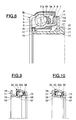
- the thrust bearing is similar to that of FIG. 1 except that the groove 17 is disposed on a substantially cylindrical portion 24 of the inner ring 1 between the raceway 2 of the rolling elements 3 and the portion radial 4.
- the annular portion 21 of the cage 8 is disposed between the rolling elements 3 and the seal 9.
- the bore 21a of the annular portion 21 of the cage 8 comprises lugs 22 similar to those of FIG. 1 and projecting radially in the groove 17.
- Figures 9 and 10 illustrate two stages of mounting a bearing identical to that of Figure 7.
- For mounting the thrust bearing first take the outer ring 55. There is in the raceway 55b of the outer ring 55 a row of balls 53 held by their holding cage 58. The seal 59 is fitted. There is then a sub-assembly from which the balls 53 cannot escape and inside which said balls 53 are well protected. Then by an axial movement, an inner ring 51 is brought facing the sub-assembly comprising the outer ring 55, the balls 53, the cage 58 and the seal 59.
- the pins 72 of the cage 58 come into contact with the front end of the inner ring 51, flex when they disappear, then resume their initial shape by projecting into the groove 67.
- the balls 53 come into contact with the raceway 52 of the inner ring 51.
- the thrust bearing is thus protected against accidental disassembly, the balls 53 being, in one direction in axial abutment against the raceway 55b of the outer ring 55 and in the other direction capable of coming into abutment contact with the seal 59, and, in one direction, in abutment against the radial edge 68 of the inner ring 51 by means of the cage 58 and the pins 72 and, in the other direction, in axial abutment against the path bearing 52 of the inner ring 51.
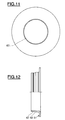
- Figures 11 and 12 show the manufacturing without removal of chips from the inner ring 51 provided with the groove 67.
- a sheet metal blank (Figure 11) in the form of a flat disc, the imprint of the groove 67 is formed. by flat stamping then the inner ring 51 by stamping the blank ( Figure 12).
- An inner ring 51 is thus obtained economically provided with the groove 67, thus avoiding operations of resumption by turning or grinding for the machining of said groove.
- raceway obtained by stamping has the desired profile and a good surface condition, a simple lapping of the groove will be sufficient to give the raceway the final surface condition required in terms of roughness.
- the manufacture of the inner rings is simplified by the elimination of the step.
- the rings can be obtained directly by stamping, then heat treatment and lapping of the grooves by eliminating the rectification step.
Landscapes
- Engineering & Computer Science (AREA)
- General Engineering & Computer Science (AREA)
- Mechanical Engineering (AREA)
- Rolling Contact Bearings (AREA)
- Mechanical Operated Clutches (AREA)
Applications Claiming Priority (2)
| Application Number | Priority Date | Filing Date | Title |
|---|---|---|---|
| FR9605860 | 1996-05-10 | ||
| FR9605860A FR2748535B1 (fr) | 1996-05-10 | 1996-05-10 | Roulement de butee d'embrayage avec cage a retenue axiale |
Publications (2)
| Publication Number | Publication Date |
|---|---|
| EP0806582A2 true EP0806582A2 (de) | 1997-11-12 |
| EP0806582A3 EP0806582A3 (de) | 1999-12-08 |
Family
ID=9492025
Family Applications (1)
| Application Number | Title | Priority Date | Filing Date |
|---|---|---|---|
| EP97401019A Withdrawn EP0806582A3 (de) | 1996-05-10 | 1997-05-06 | Kupplungsausrücklager mit einem Käfig mit axialer Arretierung |
Country Status (2)
| Country | Link |
|---|---|
| EP (1) | EP0806582A3 (de) |
| FR (1) | FR2748535B1 (de) |
Cited By (13)
| Publication number | Priority date | Publication date | Assignee | Title |
|---|---|---|---|---|
| FR2780117A1 (fr) * | 1998-06-22 | 1999-12-24 | Skf France | Palier a roulement |
| DE19908148A1 (de) * | 1999-02-25 | 2000-08-31 | Schaeffler Waelzlager Ohg | Ausrücklager für Kupplungen |
| FR2828534A1 (fr) * | 2001-08-10 | 2003-02-14 | Valeo | Butee de debrayage pour la commande d'un embrayage a friction du type tire et embrayage comportant une telle butee |
| FR2869081A1 (fr) * | 2004-04-20 | 2005-10-21 | Skf Ab | Palier a roulement |
| WO2011023485A1 (en) * | 2009-08-28 | 2011-03-03 | Aktiebolaget Skf | Rolling bearing device for steering column |
| WO2012072110A1 (en) * | 2010-11-30 | 2012-06-07 | Aktiebolaget Skf | Comb cage for ball bearing and ball bearing with such a cage |
| FR2984435A1 (fr) * | 2011-12-19 | 2013-06-21 | Skf Ab | Butee d'embrayage-debrayage, de suspension ou de direction, et vehicule automobile equipe d'une telle butee |
| FR2985555A1 (fr) * | 2012-01-09 | 2013-07-12 | Ntn Snr Roulements | Butee d'embrayage de vehicule automobile |
| DE102012205923A1 (de) * | 2012-04-12 | 2013-10-17 | Schaeffler Technologies AG & Co. KG | Lagerinnenring für ein Rillenkugellager, Rillenkugellager mit diesem Lagerinnenring sowie Verfahren zur Herstellung eines solchen Lagerinnenrings |
| EP2085633A3 (de) * | 2008-01-31 | 2017-01-18 | JTEKT Corporation | Kupplungsausrücklager |
| CN110173509A (zh) * | 2018-02-21 | 2019-08-27 | Ntn-Snr轴承股份有限公司 | 在滚道后侧配备有密封装置的机动车辆离合器分离轴承 |
| CN111981056A (zh) * | 2019-05-24 | 2020-11-24 | 斯凯孚公司 | 密封的离合器推力轴承装置及包括这样的装置的传动系统 |
| CN115681335A (zh) * | 2022-10-08 | 2023-02-03 | 宁波锴立精密轴承有限公司 | 一种滚珠深沟保持器和轴承 |
Family Cites Families (7)
| Publication number | Priority date | Publication date | Assignee | Title |
|---|---|---|---|---|
| DE2108562C2 (de) * | 1971-02-23 | 1982-02-25 | Industriewerk Schaeffler Ohg, 8522 Herzogenaurach | Kunststoffkäfig für Schrägkugellager |
| DE2329911A1 (de) * | 1973-06-12 | 1975-01-09 | Joerg Schwarzbich | Schraegkugellager |
| FR2308013A1 (fr) * | 1975-04-18 | 1976-11-12 | Ina Roulements Sa | Palier a roulement |
| DE2651827A1 (de) * | 1976-11-13 | 1978-05-18 | Kugelfischer G Schaefer & Co | Vollrolliges bzw. vollkugeliges waelzlager |
| DE2739367A1 (de) * | 1977-09-01 | 1978-10-26 | Kugelfischer G Schaefer & Co | Einbaufertiges, selbsthaltendes schraegrollenlager |
| US4523862A (en) * | 1983-06-07 | 1985-06-18 | Koyo Seiko Company Limited | Tapered roller bearing |
| FR2663702B1 (fr) * | 1990-06-21 | 1995-05-12 | Skf France | Butee d'embrayage comportant des moyens de solidarisation avec l'organe de manóoeuvre. |
-
1996
- 1996-05-10 FR FR9605860A patent/FR2748535B1/fr not_active Expired - Fee Related
-
1997
- 1997-05-06 EP EP97401019A patent/EP0806582A3/de not_active Withdrawn
Cited By (15)
| Publication number | Priority date | Publication date | Assignee | Title |
|---|---|---|---|---|
| FR2780117A1 (fr) * | 1998-06-22 | 1999-12-24 | Skf France | Palier a roulement |
| DE19908148A1 (de) * | 1999-02-25 | 2000-08-31 | Schaeffler Waelzlager Ohg | Ausrücklager für Kupplungen |
| FR2828534A1 (fr) * | 2001-08-10 | 2003-02-14 | Valeo | Butee de debrayage pour la commande d'un embrayage a friction du type tire et embrayage comportant une telle butee |
| FR2869081A1 (fr) * | 2004-04-20 | 2005-10-21 | Skf Ab | Palier a roulement |
| EP2085633A3 (de) * | 2008-01-31 | 2017-01-18 | JTEKT Corporation | Kupplungsausrücklager |
| US8926189B2 (en) | 2009-08-28 | 2015-01-06 | Aktiebolaget Skf | Rolling bearing device for steering column |
| WO2011023485A1 (en) * | 2009-08-28 | 2011-03-03 | Aktiebolaget Skf | Rolling bearing device for steering column |
| FR2949523A1 (fr) * | 2009-08-28 | 2011-03-04 | Skf Ab | Dispositif de palier a roulement pour colonne de direction |
| WO2012072110A1 (en) * | 2010-11-30 | 2012-06-07 | Aktiebolaget Skf | Comb cage for ball bearing and ball bearing with such a cage |
| FR2984435A1 (fr) * | 2011-12-19 | 2013-06-21 | Skf Ab | Butee d'embrayage-debrayage, de suspension ou de direction, et vehicule automobile equipe d'une telle butee |
| FR2985555A1 (fr) * | 2012-01-09 | 2013-07-12 | Ntn Snr Roulements | Butee d'embrayage de vehicule automobile |
| DE102012205923A1 (de) * | 2012-04-12 | 2013-10-17 | Schaeffler Technologies AG & Co. KG | Lagerinnenring für ein Rillenkugellager, Rillenkugellager mit diesem Lagerinnenring sowie Verfahren zur Herstellung eines solchen Lagerinnenrings |
| CN110173509A (zh) * | 2018-02-21 | 2019-08-27 | Ntn-Snr轴承股份有限公司 | 在滚道后侧配备有密封装置的机动车辆离合器分离轴承 |
| CN111981056A (zh) * | 2019-05-24 | 2020-11-24 | 斯凯孚公司 | 密封的离合器推力轴承装置及包括这样的装置的传动系统 |
| CN115681335A (zh) * | 2022-10-08 | 2023-02-03 | 宁波锴立精密轴承有限公司 | 一种滚珠深沟保持器和轴承 |
Also Published As
| Publication number | Publication date |
|---|---|
| FR2748535A1 (fr) | 1997-11-14 |
| FR2748535B1 (fr) | 1998-06-19 |
| EP0806582A3 (de) | 1999-12-08 |
Similar Documents
| Publication | Publication Date | Title |
|---|---|---|
| EP1489327B1 (de) | Ausrücksvorrichtung und Montageverfahren | |
| EP1225360B1 (de) | Selbstzentrierende Vorrichtung für ein Kupplungsausrücklager | |
| EP1146244B1 (de) | Kupplungsausrücklager | |
| EP0806582A2 (de) | Kupplungsausrücklager mit einem Käfig mit axialer Arretierung | |
| FR2756885A1 (fr) | Palier a roulement de colonne de direction pour vehicules automobiles | |
| EP1243446B1 (de) | Axialwälzlager für eine Fahrzeugaufhängung mit Rückhaltemittel | |
| EP0773384B1 (de) | Schutzflansch für Rollenlager, damit ausgerüstetes Lager und Herstellungsverfahren für einen Lagerring, der mit einem Schutzflansch versehen ist | |
| EP0561704B1 (de) | Axialwälzlager für Fahrzeugaufhängung und sein Montageverfahren | |
| EP0806581A1 (de) | Kupplungsausrücklager mit einem elastischen Ring | |
| EP1264113B1 (de) | Wälzlager für kraftfahrzeug- lenksäulen | |
| EP2142817B1 (de) | Klimaanlagenverdichter | |
| FR2883347A1 (fr) | Butee de debrayage | |
| EP0841496B1 (de) | Selbstzentrierendes Kupplungsausrücklager und Verfahren zur Montage | |
| EP1409883B1 (de) | Wälzlager für kraftfahrzeuglenksäule | |
| FR2898951A1 (fr) | Butee de debrayage auto-centreuse | |
| FR2760057A1 (fr) | Dispositif de roue libre a flasque de retenue et procede de mise en place du flasque | |
| EP0770789B1 (de) | Hydraulische Kupplungsbetätigungsvorrichtung | |
| FR2926617A1 (fr) | Installation de butee d'embrayage. | |
| EP0836685B1 (de) | Befestigung eines kupplungsrücklagers | |
| FR3032016A1 (fr) | Palier a roulement comprenant une bague d'usure, et procede de fabrication associe | |
| FR2876170A1 (fr) | Butee de debrayage autocentreuse et procede de montage | |
| FR2805579A1 (fr) | Butee de debrayage a auto-alignement par manchon elastique et palier a roulement pour butee de debrayage | |
| FR2709526A1 (fr) | Dispositif d'étanchéité pour deux pièces en mouvement rotatif l'une par rapport à l'autre et application du dispositif à un palier à roulement. | |
| FR2965599A1 (fr) | Dispositif de butee de debrayage et procede de montage associe. | |
| FR3112829A1 (fr) | Butée de débrayage et palier à roulement pour butée de débrayage |
Legal Events
| Date | Code | Title | Description |
|---|---|---|---|
| PUAI | Public reference made under article 153(3) epc to a published international application that has entered the european phase |
Free format text: ORIGINAL CODE: 0009012 |
|
| AK | Designated contracting states |
Kind code of ref document: A2 Designated state(s): DE FR GB IT |
|
| 17P | Request for examination filed |
Effective date: 19971030 |
|
| PUAL | Search report despatched |
Free format text: ORIGINAL CODE: 0009013 |
|
| AK | Designated contracting states |
Kind code of ref document: A3 Designated state(s): DE FR GB IT |
|
| 17Q | First examination report despatched |
Effective date: 20001002 |
|
| STAA | Information on the status of an ep patent application or granted ep patent |
Free format text: STATUS: THE APPLICATION HAS BEEN WITHDRAWN |
|
| 18W | Application withdrawn |
Withdrawal date: 20020227 |