EP0806571A2 - Rotierende Anordnung zur Lagerung des Rotors einer Vakuumpumpe - Google Patents
Rotierende Anordnung zur Lagerung des Rotors einer Vakuumpumpe Download PDFInfo
- Publication number
- EP0806571A2 EP0806571A2 EP96202491A EP96202491A EP0806571A2 EP 0806571 A2 EP0806571 A2 EP 0806571A2 EP 96202491 A EP96202491 A EP 96202491A EP 96202491 A EP96202491 A EP 96202491A EP 0806571 A2 EP0806571 A2 EP 0806571A2
- Authority
- EP
- European Patent Office
- Prior art keywords
- supporting
- shaft
- rotor
- bearing assembly
- rotatable
- Prior art date
- Legal status (The legal status is an assumption and is not a legal conclusion. Google has not performed a legal analysis and makes no representation as to the accuracy of the status listed.)
- Granted
Links
Images
Classifications
-
- F—MECHANICAL ENGINEERING; LIGHTING; HEATING; WEAPONS; BLASTING
- F04—POSITIVE - DISPLACEMENT MACHINES FOR LIQUIDS; PUMPS FOR LIQUIDS OR ELASTIC FLUIDS
- F04D—NON-POSITIVE-DISPLACEMENT PUMPS
- F04D29/00—Details, component parts, or accessories
- F04D29/05—Shafts or bearings, or assemblies thereof, specially adapted for elastic fluid pumps
- F04D29/056—Bearings
- F04D29/059—Roller bearings
-
- F—MECHANICAL ENGINEERING; LIGHTING; HEATING; WEAPONS; BLASTING
- F04—POSITIVE - DISPLACEMENT MACHINES FOR LIQUIDS; PUMPS FOR LIQUIDS OR ELASTIC FLUIDS
- F04D—NON-POSITIVE-DISPLACEMENT PUMPS
- F04D19/00—Axial-flow pumps
- F04D19/02—Multi-stage pumps
- F04D19/04—Multi-stage pumps specially adapted to the production of a high vacuum, e.g. molecular pumps
-
- F—MECHANICAL ENGINEERING; LIGHTING; HEATING; WEAPONS; BLASTING
- F16—ENGINEERING ELEMENTS AND UNITS; GENERAL MEASURES FOR PRODUCING AND MAINTAINING EFFECTIVE FUNCTIONING OF MACHINES OR INSTALLATIONS; THERMAL INSULATION IN GENERAL
- F16C—SHAFTS; FLEXIBLE SHAFTS; ELEMENTS OR CRANKSHAFT MECHANISMS; ROTARY BODIES OTHER THAN GEARING ELEMENTS; BEARINGS
- F16C32/00—Bearings not otherwise provided for
- F16C32/04—Bearings not otherwise provided for using magnetic or electric supporting means
- F16C32/0406—Magnetic bearings
- F16C32/044—Active magnetic bearings
- F16C32/0442—Active magnetic bearings with devices affected by abnormal, undesired or non-standard conditions such as shock-load, power outage, start-up or touchdown
-
- F—MECHANICAL ENGINEERING; LIGHTING; HEATING; WEAPONS; BLASTING
- F16—ENGINEERING ELEMENTS AND UNITS; GENERAL MEASURES FOR PRODUCING AND MAINTAINING EFFECTIVE FUNCTIONING OF MACHINES OR INSTALLATIONS; THERMAL INSULATION IN GENERAL
- F16C—SHAFTS; FLEXIBLE SHAFTS; ELEMENTS OR CRANKSHAFT MECHANISMS; ROTARY BODIES OTHER THAN GEARING ELEMENTS; BEARINGS
- F16C39/00—Relieving load on bearings
- F16C39/02—Relieving load on bearings using mechanical means
-
- F—MECHANICAL ENGINEERING; LIGHTING; HEATING; WEAPONS; BLASTING
- F16—ENGINEERING ELEMENTS AND UNITS; GENERAL MEASURES FOR PRODUCING AND MAINTAINING EFFECTIVE FUNCTIONING OF MACHINES OR INSTALLATIONS; THERMAL INSULATION IN GENERAL
- F16C—SHAFTS; FLEXIBLE SHAFTS; ELEMENTS OR CRANKSHAFT MECHANISMS; ROTARY BODIES OTHER THAN GEARING ELEMENTS; BEARINGS
- F16C2360/00—Engines or pumps
- F16C2360/44—Centrifugal pumps
- F16C2360/45—Turbo-molecular pumps
Definitions
- the present invention is directed to a bearing assembly for rotatably supporting the rotor of a vacuum pump.
- the invention is concerned with a bearing assembly for supporting the shaft of a rotor in a vacuum pump of the turbomolecular type.
- a vacuum pump is substantially formed by an outer case housing a number of gas pumping stages.
- the gas pumping stages generally comprise a plurality of stator rings integral with the pump body and cooperating with a plurality of rotor disks integrally mounted on a rotatable shaft rotated by the pump motor.
- the pumping stages provide a region for the gas passage, known as pumping channel, in which the surfaces of a rotor disk and of the corresponding stator disk are relatively spaced apart, and high tightness zones in which the surface of a rotor and that of the corresponding stator disk are very near to each other.
- the rotor disks can be either flat disks or disks provided with a number of tilted and closely spaced vanes.
- a vacuum pump of the turbomolecular type comprises both flat disks and disks equipped with vanes and is capable to achieve vacuum levels in the order of 10 -8 Pa.
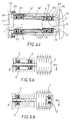
- the shaft A of a vacuum pump is rotatably supported through a pair of rotatable supports or bearings C and D, for example ball bearings, disposed between the shaft A and the body E of the vacuum pump.
- Figure 5a illustrates a first embodiment of the prior art in which both the bearings C and D are located on the same side of the pump with respect to the pump rotor F that is integral with the rotatable shaft A.
- Figure 5b illustrates a second embodiment of the prior art in which the bearings C and D' are located at the opposed ends of the pump rotor F that is integral with the rotatable shaft A.
- gas mixtures such as, for example, HCl, HBr, Cl 2 , Fl 2 , NH 3 , etc...., that are corrosive, as it is well known.
- a known solution for preventing the breaking of the bearings provides for using auxiliary mechanical bearings that intervene only in conditions suc as an excessive applied load, a malfunction of the magnetic bearings, or when these latter are no longer fed, etc..
- auxiliary bearings are commonly known as emergency or “backup” bearings and are generally positioned in accordance with the arrangements shown in the already described Figures 5a and 5b with reference to the prior art, leaving a gap between the rotatable ring of the backup supports and the rotor of the pump.
- Such a gap allows the free rotation of the pump rotor when the magnetic bearings are working without interfering with the backup bearings.
- This second object of the present invention is achieved through a bearing assembly as claimed in claim 8.
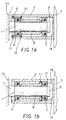
- a rotatable bearing assembly according to the present invention comprises a journal member 1, removably secured to the base 13 of the body of a vacuum pump and surrounded by a rotatable hollow shaft 2 having a substantially cylindrical inner cavity 14, to which the rotor 3 (only partially shown in the figure) is firmly secured, and a pair of ball (or roll) bearings 4 and 5 interposed between the journal 1 and the inner surface of the cylindrical cavity 14 of the shaft 2 housing the journal 1.
- the bearings 4 and 5 are kept in the desired position on the supporting journal 1 by two sleeve collars 6 and 7, fastened at the opposed ends of the journal 1, near the closed end and the open end (or base) of hollow shaft 2, respectively, and by a sleeve 8 positioned between the bearings 4 and 5.
- the sleeve 8 further accomplishes the purpose of strengthening and stiffening the journal 1 to prevent an excessive bending thereof that might bring the rotatable shaft 2 and the rotor 3 in contact with the pump stationary parts.
- Axially restraining rings 9 and 10 are further provided that are partially received in annular radial grooves 11 and 12 of the inner cavity of the shaft 2 of the vacuum pump.
- the axially restraining rings 9 and 10 prevent the disengagement of the shaft 2 from the journal 1 when this latter is rotated with respect to the former.
- FIG. 1b there is shown another embodiment of the bearing assembly of the invention in which the cylindrical cross-section of the inner cavity 14 in the rotatable shaft 2 is narrower (i.e. provided with a reduced diameter portion) 16 at the cavity end adjacent the free end of the journal 1 thus forming an abutting step or shoulder 15 for the ball bearing 5.
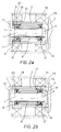
- FIGs 2a and 2b it is shown a further embodiment of the bearing assembly of the present invention in which the main means for rotatably supporting the shaft 2 comprises magnetic bearings, schematically represented in Figures 2a and indicated by the references 18 and 19, while the mechanical bearings assembly 4', 5' acts as an auxiliary supporting means.
- a gap 20 is formed between the auxiliary bearings 4' and 5' and the shaft 2 for allowing an unhindered rotation of the shaft 2 with respect of the auxiliary bearings 4' and 5' when the main magnetic bearings 18 and 19 are opering, while allowing the contact of the inner surface of the cavity 14 of the shaft 2 with the auxiliary bearings 4' and 5' in case of failure of the magnetic bearings 18 and 19 or when they are subjected to an excessive load.
- Figure 3 illustrates a further embodiment of the invention in which the bearings 4' and 5' are coupled with the bearings 21 and 22, respectively, in order to obtain an axial preloading.
- the axial preloading of the auxiliary bearings 4' and 5' 2 is useful both for a more precise restraint of the rotor in case of contact with the auxiliary bearings 4' and 5' and for preventing a damage of the auxiliary bearings 4' and 5' because of the position that the rolling members could take with respect to the rolling races.
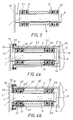
- Figures 4a to 4c relate to arrangements in which the bearings 4' and 5' operate as auxiliary bearings and are provided with an axial preloading, as in the case of Figure 3.
- the arrangements of Figures 4a to 4c can be used also in embodiments that do not provide an axial preloading and in which such bearings constitute the main supports of the pump shaft.
- Figure 4a illustrates a first embodiment of the axial restraining means provided with a cylindrical sleeve 23, located in the cavity 14 of the shaft 2 between the outermost pair of bearings 4', 21 and the hollow rotor shaft 2 of the vacuum pump.
- the free end of the cylindrical sleeve 23 that protrudes ouside the shaft 2 has a rim 26 outwardly folded at 90° through which pass screws 25 for firmly fastening said rim 26 to a reinforcing rim 24 formed on the base of the shaft 2.
- Figure 4b illustrates a second embodiment of the axial restraining means in which the narrowing 16' of the inner cavity 14 of the shaft 2 is located near the outermost (pair of) bearings 21 and 4', said narrowing 16' defining an abutment step 15' for a cylindrical sleeve 23' located within the cavity 14 of the shaft 2 between the bearings 4' and 21 and the rotor shaft 2 of the vacuum pump.
- the surface of said cap 28 pressing the cylindrical sleeve 23' is further provided with a circular groove 29 for receiving the free end of said cylindrical sleeve 23'.
- Figure 4c illustrates a third embodiment of the axial restraining means in which the inner cavity 14 of the shaft 2 has a first narrowing 16 and a second narrowing 16' positioned at the innermost bearings 5' and 22 and at the outermost bearings 4' and 21, respectively, and defining as many abutment steps 15 and 15', respectively.
- a cylindrical sleeve 23'' having a front portion with a small cross-section and a rear portion with a larger cross-section enters the cavity 14 of the shaft 2 between the bearings 4', 21 and the rotor shaft 2 of the vacuum pump.
- such cylindrical sleeve 23'' defines an axial stop shoulder for the innermost bearings 5', 22 preventing the withdrawal of the shaft 2 from the supporting journal 1 on which there are mounted the bearings 4', 21, 5' and 22.
- such cylindrical sleeve 23'' is further provided with a rim 30 outwardly folded at 90°, through which pass screws 25 firmly securing the rim 30 to a reinforcement rim 24 provided on the base of the shaft 2.
- a gap 20 is provided between the moving parts an the bearings 4', 21, 5' and 22 for allowing the free rotation of the shaft 2 with respect to the auxiliary bearings when the main magnetic supports are operating.
- the free end of the supporting journal 1 can have a narrowing 31 on which there are mounted innermost bearings 5' and 22 having the same or a smaller size than the outermost bearings.
- the mechanical supports both main or auxiliary supports, can have a small size, and since they are housed within the rotor shaft, they are kept separated from the pump zones where flows the gas to be pumped, so that they are protected against the gas corrosive action.
- a further advantage of the invention consists in that since the rotor shaft is partially hollow, it exhibits a larger resistance to bending stress and a smaller mass that increase the flexional stiffness/mass ratio as it is often useful for quick rotating rotors.
- a not negligible advantage of the invention consists in that the supporting journal on which the bearings are mounted can easily be replaced by withdrawing it from the rotor shaft of the pump without any need of disassembling the shaft.
Landscapes
- Engineering & Computer Science (AREA)
- General Engineering & Computer Science (AREA)
- Mechanical Engineering (AREA)
- Non-Positive Displacement Air Blowers (AREA)
- Rolling Contact Bearings (AREA)
- Support Of The Bearing (AREA)
Applications Claiming Priority (2)
| Application Number | Priority Date | Filing Date | Title |
|---|---|---|---|
| ITTO960380 | 1996-05-09 | ||
| IT96TO000380A IT1285864B1 (it) | 1996-05-09 | 1996-05-09 | Gruppo girevole di supporto per rotatore di pompa da vuoto. |
Publications (3)
| Publication Number | Publication Date |
|---|---|
| EP0806571A2 true EP0806571A2 (de) | 1997-11-12 |
| EP0806571A3 EP0806571A3 (de) | 1998-09-23 |
| EP0806571B1 EP0806571B1 (de) | 1999-10-13 |
Family
ID=11414620
Family Applications (1)
| Application Number | Title | Priority Date | Filing Date |
|---|---|---|---|
| EP96202491A Expired - Lifetime EP0806571B1 (de) | 1996-05-09 | 1996-09-07 | Rotierende Anordnung zur Lagerung des Rotors einer Vakuumpumpe |
Country Status (4)
| Country | Link |
|---|---|
| EP (1) | EP0806571B1 (de) |
| JP (1) | JP4001403B2 (de) |
| DE (1) | DE69604649T2 (de) |
| IT (1) | IT1285864B1 (de) |
Cited By (3)
| Publication number | Priority date | Publication date | Assignee | Title |
|---|---|---|---|---|
| WO1999046510A1 (en) * | 1998-03-10 | 1999-09-16 | Varian, Inc. | Vacuum pump with magnetic bearing system and back-up bearings |
| FR2893684A1 (fr) * | 2005-11-24 | 2007-05-25 | Mecanique Magnetique Sa Soc D | Agencement de paliers de secours pour machine tournante a paliers magnetiques actifs |
| GB2560375A (en) * | 2017-03-10 | 2018-09-12 | Edwards Ltd | Rotating machine and rotors for use therein |
Families Citing this family (1)
| Publication number | Priority date | Publication date | Assignee | Title |
|---|---|---|---|---|
| DE102008030583A1 (de) * | 2008-06-27 | 2009-12-31 | Oerlikon Leybold Vacuum Gmbh | Wellenanordnung für schnelldrehende Wellen |
Family Cites Families (4)
| Publication number | Priority date | Publication date | Assignee | Title |
|---|---|---|---|---|
| FR1304689A (fr) * | 1961-08-04 | 1962-09-28 | Snecma | Pompe à vide turbomoléculaire perfectionnée |
| DE2349033C3 (de) * | 1973-09-29 | 1984-08-30 | Leybold-Heraeus Gmbh, 5000 Koeln | Turbomolekularpumpe |
| JPH0772556B2 (ja) * | 1988-03-18 | 1995-08-02 | 株式会社荏原製作所 | ターボ分子ポンプ |
| JPH0261387A (ja) * | 1988-08-24 | 1990-03-01 | Seiko Seiki Co Ltd | ターボ分子ポンプ |
-
1996
- 1996-05-09 IT IT96TO000380A patent/IT1285864B1/it active IP Right Grant
- 1996-09-07 EP EP96202491A patent/EP0806571B1/de not_active Expired - Lifetime
- 1996-09-07 DE DE69604649T patent/DE69604649T2/de not_active Expired - Lifetime
-
1997
- 1997-04-30 JP JP12472797A patent/JP4001403B2/ja not_active Expired - Fee Related
Cited By (3)
| Publication number | Priority date | Publication date | Assignee | Title |
|---|---|---|---|---|
| WO1999046510A1 (en) * | 1998-03-10 | 1999-09-16 | Varian, Inc. | Vacuum pump with magnetic bearing system and back-up bearings |
| FR2893684A1 (fr) * | 2005-11-24 | 2007-05-25 | Mecanique Magnetique Sa Soc D | Agencement de paliers de secours pour machine tournante a paliers magnetiques actifs |
| GB2560375A (en) * | 2017-03-10 | 2018-09-12 | Edwards Ltd | Rotating machine and rotors for use therein |
Also Published As
| Publication number | Publication date |
|---|---|
| DE69604649D1 (de) | 1999-11-18 |
| JPH1061663A (ja) | 1998-03-06 |
| EP0806571B1 (de) | 1999-10-13 |
| ITTO960380A1 (it) | 1997-11-09 |
| EP0806571A3 (de) | 1998-09-23 |
| JP4001403B2 (ja) | 2007-10-31 |
| ITTO960380A0 (it) | 1996-05-09 |
| DE69604649T2 (de) | 2000-07-06 |
| IT1285864B1 (it) | 1998-06-24 |
Similar Documents
| Publication | Publication Date | Title |
|---|---|---|
| EP2910789B1 (de) | Dichtungsanordnung für einen Brennstoffzellenverdichter | |
| KR100999015B1 (ko) | 터보 기계 | |
| US20090028731A1 (en) | Ball bearing and a vacuum pump that is equipped with a bearing of this type | |
| US5531564A (en) | Centrifugal pump | |
| US20060181168A1 (en) | Pump motor with bearing preload | |
| US20040005228A1 (en) | Motor driven centrifugal compressor/blower | |
| EP1618308B1 (de) | Vakuumpumpe | |
| CN109944643A (zh) | 用于直接驱动的压缩机的联接件 | |
| US10794390B2 (en) | Modular turbo compressor shaft | |
| US9771940B2 (en) | Vacuum pump | |
| US6661143B1 (en) | Bearing unit with magnetic bearing protection upon rotation stoppage | |
| US5380171A (en) | Turbo vacuum pump | |
| US5501583A (en) | Turbo vacuum pump | |
| EP0806571B1 (de) | Rotierende Anordnung zur Lagerung des Rotors einer Vakuumpumpe | |
| JP4928265B2 (ja) | 多段遠心ポンプ | |
| US5833374A (en) | Rotatable assembly for supporting of the rotor of a vacuum pump | |
| EP1167793A2 (de) | Ein Wälzlager für einen Elektromotor | |
| US5451147A (en) | Turbo vacuum pump | |
| US8459931B2 (en) | Turbo-molecular pump | |
| US7896625B2 (en) | Vacuum pumping system and method of operating a vacuum pumping arrangement | |
| JP7534466B2 (ja) | ホルベックポンプ段の吸引能力が改善された真空ポンプ | |
| US20230228275A1 (en) | Sealing system for magnetic levitating centrifugal compressor and magnetic levitating centrifugal compressor | |
| US20250361872A1 (en) | Sealing system for magnetic levitating centrifugal compressor and magnetic levitating centrifugal compressor | |
| CN218771547U (zh) | 一种高速电机的轴承结构及高速离心风机 | |
| US20260071631A1 (en) | Shut-off valve and vacuum pump |
Legal Events
| Date | Code | Title | Description |
|---|---|---|---|
| PUAI | Public reference made under article 153(3) epc to a published international application that has entered the european phase |
Free format text: ORIGINAL CODE: 0009012 |
|
| AK | Designated contracting states |
Kind code of ref document: A2 Designated state(s): DE FR GB |
|
| PUAL | Search report despatched |
Free format text: ORIGINAL CODE: 0009013 |
|
| AK | Designated contracting states |
Kind code of ref document: A3 Designated state(s): DE FR GB |
|
| 17P | Request for examination filed |
Effective date: 19981008 |
|
| GRAG | Despatch of communication of intention to grant |
Free format text: ORIGINAL CODE: EPIDOS AGRA |
|
| GRAG | Despatch of communication of intention to grant |
Free format text: ORIGINAL CODE: EPIDOS AGRA |
|
| GRAH | Despatch of communication of intention to grant a patent |
Free format text: ORIGINAL CODE: EPIDOS IGRA |
|
| 17Q | First examination report despatched |
Effective date: 19990316 |
|
| GRAH | Despatch of communication of intention to grant a patent |
Free format text: ORIGINAL CODE: EPIDOS IGRA |
|
| GRAA | (expected) grant |
Free format text: ORIGINAL CODE: 0009210 |
|
| AK | Designated contracting states |
Kind code of ref document: B1 Designated state(s): DE FR GB |
|
| REF | Corresponds to: |
Ref document number: 69604649 Country of ref document: DE Date of ref document: 19991118 |
|
| ET | Fr: translation filed | ||
| PLBE | No opposition filed within time limit |
Free format text: ORIGINAL CODE: 0009261 |
|
| STAA | Information on the status of an ep patent application or granted ep patent |
Free format text: STATUS: NO OPPOSITION FILED WITHIN TIME LIMIT |
|
| 26N | No opposition filed | ||
| REG | Reference to a national code |
Ref country code: GB Ref legal event code: IF02 |
|
| PGFP | Annual fee paid to national office [announced via postgrant information from national office to epo] |
Ref country code: FR Payment date: 20100930 Year of fee payment: 15 |
|
| PGFP | Annual fee paid to national office [announced via postgrant information from national office to epo] |
Ref country code: GB Payment date: 20100927 Year of fee payment: 15 |
|
| REG | Reference to a national code |
Ref country code: GB Ref legal event code: 732E Free format text: REGISTERED BETWEEN 20110505 AND 20110511 |
|
| REG | Reference to a national code |
Ref country code: DE Ref legal event code: R082 Ref document number: 69604649 Country of ref document: DE Representative=s name: DILG HAEUSLER SCHINDELMANN PATENTANWALTSGESELL, DE Effective date: 20110809 Ref country code: DE Ref legal event code: R081 Ref document number: 69604649 Country of ref document: DE Owner name: AGILENT TECHNOLOGIES, INC., SANTA CLARA, US Free format text: FORMER OWNER: VARIAN S.P.A., LEINI, TURIN/TORINO, IT Effective date: 20110809 Ref country code: DE Ref legal event code: R081 Ref document number: 69604649 Country of ref document: DE Owner name: AGILENT TECHNOLOGIES ITALIA S.P.A., IT Free format text: FORMER OWNER: VARIAN S.P.A., LEINI, IT Effective date: 20110809 Ref country code: DE Ref legal event code: R081 Ref document number: 69604649 Country of ref document: DE Owner name: AGILENT TECHNOLOGIES, INC., US Free format text: FORMER OWNER: VARIAN S.P.A., LEINI, IT Effective date: 20110809 |
|
| REG | Reference to a national code |
Ref country code: FR Ref legal event code: TP Owner name: AGILENT TECHNOLOGIES ITALIA, S.P.A., IT Effective date: 20110922 |
|
| GBPC | Gb: european patent ceased through non-payment of renewal fee |
Effective date: 20110907 |
|
| REG | Reference to a national code |
Ref country code: FR Ref legal event code: ST Effective date: 20120531 |
|
| PG25 | Lapsed in a contracting state [announced via postgrant information from national office to epo] |
Ref country code: GB Free format text: LAPSE BECAUSE OF NON-PAYMENT OF DUE FEES Effective date: 20110907 Ref country code: FR Free format text: LAPSE BECAUSE OF NON-PAYMENT OF DUE FEES Effective date: 20110930 |
|
| REG | Reference to a national code |
Ref country code: DE Ref legal event code: R082 Ref document number: 69604649 Country of ref document: DE Representative=s name: DILG HAEUSLER SCHINDELMANN PATENTANWALTSGESELL, DE |
|
| REG | Reference to a national code |
Ref country code: DE Ref legal event code: R082 Ref document number: 69604649 Country of ref document: DE Representative=s name: DILG HAEUSLER SCHINDELMANN PATENTANWALTSGESELL, DE |
|
| REG | Reference to a national code |
Ref country code: DE Ref legal event code: R082 Ref document number: 69604649 Country of ref document: DE Representative=s name: DILG HAEUSLER SCHINDELMANN PATENTANWALTSGESELL, DE Effective date: 20130521 Ref country code: DE Ref legal event code: R082 Ref document number: 69604649 Country of ref document: DE Representative=s name: DILG HAEUSLER SCHINDELMANN PATENTANWALTSGESELL, DE Effective date: 20130201 Ref country code: DE Ref legal event code: R081 Ref document number: 69604649 Country of ref document: DE Owner name: AGILENT TECHNOLOGIES, INC., SANTA CLARA, US Free format text: FORMER OWNER: AGILENT TECHNOLOGIES ITALIA S.P.A., CERNUSCO SUL NAVIGLIO, MILANO, IT Effective date: 20130521 Ref country code: DE Ref legal event code: R081 Ref document number: 69604649 Country of ref document: DE Owner name: AGILENT TECHNOLOGIES, INC., US Free format text: FORMER OWNER: AGILENT TECHNOLOGIES ITALIA S.P.A., CERNUSCO SUL NAVIGLIO, IT Effective date: 20130521 |
|
| PGFP | Annual fee paid to national office [announced via postgrant information from national office to epo] |
Ref country code: DE Payment date: 20140903 Year of fee payment: 19 |
|
| REG | Reference to a national code |
Ref country code: DE Ref legal event code: R119 Ref document number: 69604649 Country of ref document: DE |
|
| PG25 | Lapsed in a contracting state [announced via postgrant information from national office to epo] |
Ref country code: DE Free format text: LAPSE BECAUSE OF NON-PAYMENT OF DUE FEES Effective date: 20160401 |