EP0806518B1 - Device for kneading high consistency pulp - Google Patents
Device for kneading high consistency pulp Download PDFInfo
- Publication number
- EP0806518B1 EP0806518B1 EP97104827A EP97104827A EP0806518B1 EP 0806518 B1 EP0806518 B1 EP 0806518B1 EP 97104827 A EP97104827 A EP 97104827A EP 97104827 A EP97104827 A EP 97104827A EP 0806518 B1 EP0806518 B1 EP 0806518B1
- Authority
- EP
- European Patent Office
- Prior art keywords
- teeth
- kneading
- pulp
- angle
- kneading device
- Prior art date
- Legal status (The legal status is an assumption and is not a legal conclusion. Google has not performed a legal analysis and makes no representation as to the accuracy of the status listed.)
- Expired - Lifetime
Links
Images
Classifications
-
- D—TEXTILES; PAPER
- D21—PAPER-MAKING; PRODUCTION OF CELLULOSE
- D21B—FIBROUS RAW MATERIALS OR THEIR MECHANICAL TREATMENT
- D21B1/00—Fibrous raw materials or their mechanical treatment
- D21B1/04—Fibrous raw materials or their mechanical treatment by dividing raw materials into small particles, e.g. fibres
- D21B1/12—Fibrous raw materials or their mechanical treatment by dividing raw materials into small particles, e.g. fibres by wet methods, by the use of steam
- D21B1/30—Defibrating by other means
- D21B1/34—Kneading or mixing; Pulpers
- D21B1/342—Mixing apparatus
Definitions
- the invention relates to a device for kneading highly consistent fibrous material according to the preamble of claim 1.
- a kneading device is e.g. B. known from DE-42 37 433 A1.
- This for kneading Device suitable for waste paper serves to intensively mechanically and possibly the substance can also be processed thermally, thereby removing the contaminants contained in the fibers can be detached, crushed and / or brought below the visibility limit.
- the starting material intended for the kneading process already has a pasty or soft-crumbly shape, so is no longer with wood chips or still coarser substances comparable. Other than z. B.
- the pulp in pulp refiners in such machines the pulp is not in a pumpable suspension edited, but just as a high consistency substance, preferably with one Dry content between 15 and 40%. In this way, considerable Transfer shear forces into the fiber material, whereby the stated goals can be achieved, without any significant change in fiber length.
- the effect of mechanical treatment is further enhanced by heat, e.g. by setting a fiber temperature of 90 ° Celsius or even higher.
- the substance In the kneader, the substance usually stays in for 15 seconds to several minutes the processing rooms and is due to the distance of more than 3 mm between the tools are mainly processed by fiber-fiber friction. As is known this protects the fiber and the processing tools become slow worn.
- the basic structure of the kneader is almost always as in the example of DE-42 37 433 A1 recognizable:
- the rotor is essentially cylindrical, and the material becomes conveyed axially between standing and moving kneading teeth.
- Such kneaders have long proven themselves especially for the use of waste paper.
- the transportation of the Material through the processing zone is usually both by tilting the Machining teeth and secured by a suitable conveyor, which e.g. is designed as a helix on the kneader shaft.
- the funding parameters are so practically firm.
- the invention is therefore based on the object of a device for kneading to create highly consistent fibrous material, which without any significant additional effort Possibility to change the transport movement in the processing zone.
- the front of the teeth of such a kneading tool moves relative to the Pulp too. Since the incline on the front is a sliding and Deflection movement of the substance to be transported in the transport direction causes the mass transfer is supported in the kneader. Prerequisite for this is the relative movement between the bevel and the pulp, either by doing so can arise that the tooth in question belongs to the moving kneading tool or in that a fixed tooth of a material moved in the circumferential direction is flowed to.
- the device equipped according to the invention now exists the possibility of simply turning a tooth or a group of teeth one or more kneading tools the surface of the previously used as the back To bring tooth to the front.
- the transport effect of the angle depends on the incline in relation to the direction of movement of the tooth or the material on the unmoved tooth, can be turned by turning such a tooth, e.g. by 180 ° with different angles of the slopes also a different one Transport effect can be achieved.
- the mass transfer in the kneader can be used for various applications and the same kneader are desired differently.
- a part of or all accordingly equipped teeth are turned. Even in the cases where the Slopes on the front and back are the same, can be turned one less worn area for transporting the fabric.
- the slope can even be chosen so that the Material transport brakes.
- an upstream or downstream one would Transport device can still be forced throughput through the machine have to.
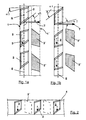
- Figure 1a shows in a developed form the supervision of the part of a movable Kneading tool 1, which belongs to a kneader with an axial flow of material.
- a movable Kneading tool which belongs to a kneader with an axial flow of material.
- Cut teeth are indicated 2 ' a fixed kneading tool.
- the teeth 2, 2 ' are both on the front as well also bevelled on the back.
- everyone has Teeth are essentially the same shape, but this does not always have to be the case (see also Fig. 3). Due to their arrangement in the kneading device, the teeth 2 at Operation moved in the circumferential direction (arrow 3).
- a plane E is spanned here, shown in section.
- the The direction of transport T of the fibrous material is perpendicular to this plane E.
- the angles which have the bevels in relation to the transport direction T are at an angle ⁇ 1 Front and angle ⁇ 2 on the back - each in the position before turning of the tooth - specified.
- Fig. 1 b shows the parts of Fig. 1 a after turning the teeth 2 and 2 'through 180 °.
- the transport effect on the front of the teeth is because of the lower Inclination less. Of course, these tooth surfaces can also be curved.
- the decisive factor is their transport effect.
- Figure 2 shows a slightly different attachment of the device to the invention belonging teeth 2.
- the turning of the teeth can be done Turn this bar 4 done.
- Such a bar can be used as a rotor or stator belong on which it is attached along its length substantially axially aligned.
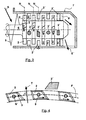
- Figure 3 shows in section an axially constructed kneading device, in which the Transport movement of the fibrous material also takes place axially again.
- the presentation is rough schematic and contains e.g. only a small part of the real teeth.
- the Fibrous material S is fed into the actual feed screw 5 Machining zone pressed.
- there the teeth 2 'belonging to the stator housing 7 are shown cut.
- a part of here they have a varied, strongly rounded shape, but another part is cubic without bevels.
- Fig. 4 shows the part of a kneading tool that belongs to a radial kneader.
- the Mass transport with transport direction T thus takes place radially outwards from the inside.
- the circumferential movement (arrow 3) of the tooth base normal N 'of the teeth 2 becomes one cylindrical surface F spanned.
- the holes 9 are provided for fastening screws.
- the one to the stator belonging tooth 2 ' is only indicated. Unlike the example shown here, it can differ in shape from the moving teeth 2.
Abstract
Description
Die Erfindung betrifft eine Vorrichtung zum Kneten von hochkonsistentem Faserstoff
gemäß dem Oberbegriff des Anspruchs 1.The invention relates to a device for kneading highly consistent fibrous material
according to the preamble of
Eine Knetvorrichtung ist z. B. aus der DE-42 37 433 A1 bekannt. Diese zum Kneten von Altpapier geeignete Vorrichtung dient dazu, den Stoff intensiv mechanisch und eventuell auch thermisch zu bearbeiten, wodurch die darin enthaltenen Störstoffe von den Fasern abgelöst, zerkleinert und/oder unter die Sichtbarkeitsgrenze gebracht werden können. Es gibt auch andere Anwendungen derartiger Knetvorrichtungen. Z.B. kann darin die Faser, sei es Zellstoff oder Altpapier, so bearbeitet werden, daß sie sich kräuselt (curling). Dadurch erhält sie spezifische Verbesserungen, wie z.B. ein größeres Volumen. Der für den Knetvorgang bestimmte Ausgangsstoff hat bereits eine teigige oder weich-krümelige Form, ist also nicht mehr mit Holz-Hackschnitzeln oder noch gröberen Stoffen vergleichbar. Anders auch als z. B. bei Papierstoff-Mahlrefinern wird bei derartigen Maschinen der Faserstoff nicht in einer pumpfähigen Suspension bearbeitet, sondern eben als Hochkonsistenzstoff, vorzugsweise mit einem Trockengehalt zwischen 15 und 40 %. Auf diese Weise lassen sich beträchtliche Scherkräfte in den Faserstoff übertragen, wodurch die genannten Ziele erreichbar sind, ohne daß dabei eine wesentliche Veränderung der Faserlänge erfolgt. In vielen Fällen wird die Wirkung der mechanischen Behandlung durch Hitze weiter verstärkt, z.B. durch Einstellen einer Faserstofftemperatur von 90° Celsius oder noch darüber.A kneading device is e.g. B. known from DE-42 37 433 A1. This for kneading Device suitable for waste paper serves to intensively mechanically and possibly the substance can also be processed thermally, thereby removing the contaminants contained in the fibers can be detached, crushed and / or brought below the visibility limit. There are other applications of such kneaders. For example, can the Fiber, be it cellulose or waste paper, is processed so that it curls (curling). This gives them specific improvements, such as a bigger one Volume. The starting material intended for the kneading process already has a pasty or soft-crumbly shape, so is no longer with wood chips or still coarser substances comparable. Other than z. B. in pulp refiners in such machines the pulp is not in a pumpable suspension edited, but just as a high consistency substance, preferably with one Dry content between 15 and 40%. In this way, considerable Transfer shear forces into the fiber material, whereby the stated goals can be achieved, without any significant change in fiber length. In many cases the effect of mechanical treatment is further enhanced by heat, e.g. by setting a fiber temperature of 90 ° Celsius or even higher.
Beim Kneter verbleibt der Stoff in der Regel 15 Sekunden bis zu mehreren Minuten in den Bearbeitungsräumen und wird infolge des Abstandes von mehr als 3 mm zwischen den Werkzeugen überwiegend durch Faser-Faser-Reibung bearbeitet. Bekanntlich wird dadurch die Faser geschont und werden die Bearbeitungswerkzeuge nur langsam verschlissen. Der Grundaufbau des Kneters ist fast immer wie am Beispiel der DE-42 37 433 A1 erkennbar: Der Rotor ist im wesentlichen zylindrisch, und der Stoff wird axial zwischen stehenden und bewegten Knetzähnen hindurchgefördert. Solche Kneter haben sich besonders für den Altpapiereinsatz seit langem bewährt. Der Transport des Stoffes durch die Bearbeitungszone wird dabei meist sowohl durch Schrägstellung der Bearbeitungszähne als auch durch eine geeignete Fördereinrichtung gesichert, die z.B. als Schneckenwendel auf der Kneterwelle ausgebildet ist. Die Förderparameter liegen damit praktisch fest.In the kneader, the substance usually stays in for 15 seconds to several minutes the processing rooms and is due to the distance of more than 3 mm between the tools are mainly processed by fiber-fiber friction. As is known this protects the fiber and the processing tools become slow worn. The basic structure of the kneader is almost always as in the example of DE-42 37 433 A1 recognizable: The rotor is essentially cylindrical, and the material becomes conveyed axially between standing and moving kneading teeth. Such kneaders have long proven themselves especially for the use of waste paper. The transportation of the Material through the processing zone is usually both by tilting the Machining teeth and secured by a suitable conveyor, which e.g. is designed as a helix on the kneader shaft. The funding parameters are so practically firm.
Der Erfindung liegt daher die Aufgabe zugrunde, eine Vorrichtung zum Kneten von hochkonsistentem Faserstoff zu schaffen, die ohne nennenswerten Mehraufwand eine Änderungsmöglichkeit der Transportbewegung in der Bearbeitungszone bietet.The invention is therefore based on the object of a device for kneading to create highly consistent fibrous material, which without any significant additional effort Possibility to change the transport movement in the processing zone.
Diese Aufgabe wird durch die im Kennzeichen des Anspruchs 1 genannten Merkmale
vollständig gelöst.This object is achieved by the features mentioned in the characterizing part of
Die Vorderseite der Zähne eines solchen Knetwerkzeuges bewegt sich relativ auf den Faserstoff zu. Da die an der Vorderseite vorhandene Schräge eine Schiebe- und Umlenkbewegung des zu transportierenden Stoffes in die Transportrichtung bewirkt, findet eine Unterstützung des Stofftransportes im Kneter statt. Voraussetzung hierfür ist die Relativbewegung zwischen der Schräge und dem Faserstoff, die entweder dadurch entstehen kann, daß der betreffende Zahn zum bewegten Knetwerkzeug gehört oder dadurch, daß ein feststehender Zahn von einem in Umfangsrichtung bewegten Stoff angeströmt wird. Bei der erfindungsgemäß ausgestatteten Vorrichtung besteht nunmehr die Möglichkeit, durch einfaches Wenden eines Zahnes oder einer Gruppe von Zähnen eines oder mehrerer Knetwerkzeuge die bisher als Rückseite verwendete Fläche des Zahnes auf die Vorderseite zu bringen. Da die Transportwirkung von dem Winkel abhängt, den die Schräge gegenüber der Bewegungsrichtung des Zahnes oder des Stoffes am unbewegten Zahn einnimmt, kann durch Wenden eines solchen Zahnes, z.B. um 180° bei unterschiedlichen Winkeln der Schrägen auch eine unterschiedliche Transportwirkung erzielt werden. The front of the teeth of such a kneading tool moves relative to the Pulp too. Since the incline on the front is a sliding and Deflection movement of the substance to be transported in the transport direction causes the mass transfer is supported in the kneader. Prerequisite for this is the relative movement between the bevel and the pulp, either by doing so can arise that the tooth in question belongs to the moving kneading tool or in that a fixed tooth of a material moved in the circumferential direction is flowed to. The device equipped according to the invention now exists the possibility of simply turning a tooth or a group of teeth one or more kneading tools the surface of the previously used as the back To bring tooth to the front. Because the transport effect of the angle depends on the incline in relation to the direction of movement of the tooth or the material on the unmoved tooth, can be turned by turning such a tooth, e.g. by 180 ° with different angles of the slopes also a different one Transport effect can be achieved.
Das Wenden in der beschriebenen Form führt also auf einfache Art und Weise zu einem Ändern der Förderwirkung an dem betreffenden Zahn. Eine solche Änderung kann Vorteile bringen, wenn bei der Auslegung der Maschine Bedingungen berücksichtigt werden sollen, die nicht dem ursprünglichen Standard entsprechen. Das kann z.B. die Erfordernis eines größeren oder kleineren Durchsatzes sein. Weiterhin kann es von Vorteil sein, gezielt auf die Transportvorgänge derart Einfluß zu nehmen, daß in bestimmten Teilen der Bearbeitungszonen eine höhere Transportgeschwindigkeit und in anderen Teilen eine geringere Transportgeschwindigkeit herrschen soll. Dadurch würde eine Kompressionszone entstehen, durch die der Stoff zwangsweise hindurchtritt. Eine Kompressionszone kann z.B. als Dampfsperre dienen. Aber auch technologische Vorteile beim eigentlichen Knetvorgang sind hierdurch erzielbar. Eine Einflußnahme dieser Art auf den Stofftransport im Kneter kann aber durchaus für verschiedene Einsatzfälle ein und desselben Kneters unterschiedlich gewünscht werden. In einem solchen Falle muß zur Anpassung erfindungsgemäß lediglich ein Teil der oder alle entsprechend ausgestatteten Zähne gewendet werden. Selbst in den Fällen, in denen ursprünlich die Schrägen an der Vorder- und Rückseite gleich sind, kann durch Wenden eine weniger verschlissene Fläche zum Transport des Stoffes angeboten werden.Turning in the form described thus leads to a simple manner Change the promotional effect on the tooth in question. Such a change can Bring advantages if conditions are taken into account when designing the machine that do not meet the original standard. This can e.g. the A need for larger or smaller throughput. Furthermore, it can be from Be advantageous to influence the transport processes in such a way that in certain parts of the processing zones a higher transport speed and in other parts should have a lower transport speed. This would a compression zone is created through which the fabric forcibly passes. A Compression zone can e.g. serve as a vapor barrier. But also technological advantages this can be achieved in the actual kneading process. An influence of this kind However, the mass transfer in the kneader can be used for various applications and the same kneader are desired differently. In such a case to adapt according to the invention only a part of or all accordingly equipped teeth are turned. Even in the cases where the Slopes on the front and back are the same, can be turned one less worn area for transporting the fabric.
In bestimmten Extremfällen, bei denen eine ausgeprägte Kompression des Stoffes zonenweise gewünscht wird, kann die Schräge sogar so gewählt werden, daß sie den Stofftransport bremst. Natürlich würde durch eine vor- oder nachgelagerte Transporteinrichtung dennoch ein Durchsatz durch die Maschine erzwungen werden müssen.In certain extreme cases where there is a pronounced compression of the substance is desired zone by zone, the slope can even be chosen so that the Material transport brakes. Of course, an upstream or downstream one would Transport device can still be forced throughput through the machine have to.
Die Erfindung und ihre Vorteile werden erläutert anhand von Zeichnungen. Dabei zeigen:
- Figur 1a+1b
- einen Teil einer erfindungsgemäß ausgeführten Knetvorrichtung;
Figur 2- Variante zur Zahnbefestigung;
Figur 3- Axialmaschine, geschnitten, Seitenansicht;
Figur 4- Knetvorrichtung für eine Radialmaschine.
- Figure 1a + 1b
- part of a kneading device designed according to the invention;
- Figure 2
- Variant for tooth attachment;
- Figure 3
- Axial machine, cut, side view;
- Figure 4
- Kneading device for a radial machine.
Figur 1a zeigt in abgewickelter Form die Aufsicht auf den Teil eines bewegbaren
Knetwerkzeuges 1, welches zu einem Kneter mit axialem Stofffluß gehört. Man erkennt
eine Zahnreihe mit einer Anzahl von Zähnen 2. Geschnitten angedeutet sind die Zähne 2'
eines feststehenden Knetwerkzeuges. Die Zähne 2, 2' sind sowohl auf der Vorderseite als
auch auf der Rückseite abgeschrägt. Dabei haben in dem hier gezeigten Beispiel alle
Zähne eine im wesentlichen gleiche Form, was aber nicht immer so sein muß (s. auch
Fig. 3). Aufgrund ihrer Anordnung in der Knetvorrichtung werden die Zähne 2 bei
Betrieb in Umfangsrichtung (Pfeil 3) bewegt. Bei einer solchen Bewegung der
Zahnfußnormalen N wird hier eine Ebene E aufgespannt, im Schnitt dargestellt. Die
Transportrichtung T des Faserstoffes steht senkrecht auf dieser Ebene E. Dabei wird nur
der eigentliche Stofftransport durch den Kneter hindurch betrachtet, selbstverständlich
findet in der Regel außerdem eine Umfangsbewegung des Faserstoffes statt. Die Winkel,
die die Schrägen gegenüber der Transportrichtung T haben, sind mit Winkel α 1 an der
Vorderseite und Winkel α 2 an der Rückseite - jeweils in der Stellung vor dem Wenden
des Zahnes - angegeben.Figure 1a shows in a developed form the supervision of the part of a
Fig. 1 b stellt die Teile der Fig. 1 a nach dem Wenden der Zähne 2 und 2' um 180° dar.
Die Transportwirkung an der Vorderseite der Zähne ist wegen der geringeren
Schrägstellung geringer. Selbstverständlich könne diese Zahnflächen auch gewölbt sein.
Entscheidend ist ihre Transportwirkung.Fig. 1 b shows the parts of Fig. 1 a after turning the
Figur 2 zeigt eine etwas andere Befestigung von den zur erfindungsgemäßen Vorrichtung
gehörenden Zähnen 2. Man erkennt den Teil einer für eine Axialmaschine bestimmte
Leiste 4, welche mehrere Zähne 2 enthält, die dann zu jeweils verschiedenen
Zahnreihen dieses Knetwerkzeuges gehören. Hier kann das Wenden der Zähne durch
Wenden dieser Leiste 4 erfolgen. Eine solche Leiste kann zum Rotor oder Stator
gehören, auf dem sie ihrer Länge nach im wesentlichen axial ausgerichtet befestigt ist.Figure 2 shows a slightly different attachment of the device to the
Figur 3 zeigt im Schnitt eine axial aufgebaute Knetvorrichtung, bei der also die
Transportbewegung des Faserstoffes auch wieder axial erfolgt. Die Darstellung ist grob
schematisch und enthält z.B. nur einen geringen Teil der real vorhandenen Zähne. Der
Faserstoff S wird beim Eintrag durch eine Förderschnecke 5 in die eigentliche
Bearbeitungszone gepreßt. In dieser befinden sich mehrere Zahnreihen, deren Zähne 2,
2' alternierend angeordnet am Rotor 6 oder am Statorgehäuse 7 befestigt sind. Dabei
sind die zum Statorgehäuse 7 gehörenden Zähne 2' geschnitten gezeichnet. Ein Teil von
ihnen hat hier eine variierte, stark abgerundete Form, ein anderer Teil ist kubisch aber
ohne Anschrägungen. An einigen von der Seite sichtbaren Zähnen sind die
Zahnfußnormalen N angedeutet, deren Umfangsbewegung die Ebene E (Fig. 1 a, 1 b)
aufspannt. Der in Strömungsrichtung letzten Statorstufe folgt hier eine einstellbare
Drossel 8 zur Erzielung eines Gegendruckes. Durch diese Maßnahme kann die Wirkung
der Knetvorrichtung weiter verbessert werden. Nach Passieren der Drossel 8 tritt der
geknetete Stoff S' aus dem Statorgehäuse 7 wieder aus.Figure 3 shows in section an axially constructed kneading device, in which the
Transport movement of the fibrous material also takes place axially again. The presentation is rough
schematic and contains e.g. only a small part of the real teeth. The
Fibrous material S is fed into the
Fig. 4 zeigt den Teil eines Knetwerkzeuges, das zu einem Radialkneter gehört. Der
Stofftransport mit Transportrichtung T erfolgt also von innen radial nach außen. Durch
die Umfangsbewegung (Pfeil 3) der Zahnfußnormalen N' der Zähne 2 wird eine
zylindrische Fläche F aufgespannt. Zum Wenden der Zähne 2 werden diese einzeln
gelöst; die Löcher 9 sind für Befestigungsschrauben vorgesehen. Der zum Stator
gehörende Zahn 2' ist nur angedeutet. Abweichend vom hier gezeigten Beispiel kann er
sich in seiner Form von den bewegten Zähnen 2 durchaus unterscheiden.
Es ist bei Realisierung der Erfindung auch möglich, die zum Wenden eingerichteten
Zähne nur am Rotor oder nur am Stator vorzusehen.Fig. 4 shows the part of a kneading tool that belongs to a radial kneader. The
Mass transport with transport direction T thus takes place radially outwards from the inside. By
the circumferential movement (arrow 3) of the tooth base normal N 'of the
Claims (10)
- Device for kneading high consistency pulp (S) with at least two essentially rotationally symmetrical coaxial kneading tools (1, 1') which are movable relative to one another, and which have teeth (2, 2') disposed in annular rows between which there are tooth gaps, there being annular voids between the rows of teeth which are positioned with respect to one another such that at least one row of teeth of a kneading tool (1, 1') extends into an annular void of another kneading tool (1', 1), with the front slanting on at least a part of the teeth (2, 2'), at which slant the pulp is diverted in the direction of conveyance (T) by means of relative movement between the pulp and the surface forming the front, with the direction of conveyance (T) resulting from the throughput of the pulp through the kneading device,
characterised in that
at least a part of the teeth (2, 2') also slants at the back, that the angle (α 1) of slant on the front differs from the angle (α 2) of the back by at least 5°, and that at least a part of the teeth (2, 2') are detachably attached such that the front and back positions may be reversed by turning the teeth (2, 2'). - Kneading device according to claim 1,
characterised in that
the turning of the tooth (2, 2') takes place at an angle of 180°. - Kneading device according to claim 1 or 2,
characterised in that
the angle (α 1) of slant on the front differs from the angle (α 2) of the back by at least 15°. - Kneading device according to claim 1, 2 or 3,
characterised in that
the direction of conveyance (T) of the pulp is at a right angle to the surface (E, F) stretched out by the movement of the teeth. - Kneading device according to claim 4,
characterised in that
the direction of conveyance (T) lies in the direction of the axis of the kneading tools. - Kneading device according to claim 4,
characterised in that
the direction of conveyance (T) is radial, with its centre in the central axis of the kneading tools (1,1'). - Kneading device according to any one of the preceding claims,
characterised in that
a plurality of teeth (2, 2') of a kneading tool (1, 1') are combined on a turnable assembly segment. - Kneading device according to claim 6 and 7,
characterised in that
the assembly segment contains a closed ring. - Kneading device according to claim 8,
characterised in that
the assembly segment contains a ring segment which extends over an angle of circumference of at most 180°. - Kneading device according to claim 6 and 7,
characterised in that
the assembly segment contains lists (4) which are fastened axially on the kneading tool (1, 1') and which in each case bear teeth (2) belonging to a plurality of rows of teeth.
Applications Claiming Priority (2)
| Application Number | Priority Date | Filing Date | Title |
|---|---|---|---|
| DE19618886 | 1996-05-10 | ||
| DE19618886 | 1996-05-10 |
Publications (2)
| Publication Number | Publication Date |
|---|---|
| EP0806518A1 EP0806518A1 (en) | 1997-11-12 |
| EP0806518B1 true EP0806518B1 (en) | 2001-06-27 |
Family
ID=7793965
Family Applications (1)
| Application Number | Title | Priority Date | Filing Date |
|---|---|---|---|
| EP97104827A Expired - Lifetime EP0806518B1 (en) | 1996-05-10 | 1997-03-21 | Device for kneading high consistency pulp |
Country Status (5)
| Country | Link |
|---|---|
| US (1) | US5836689A (en) |
| EP (1) | EP0806518B1 (en) |
| AT (1) | ATE202603T1 (en) |
| DE (1) | DE59703888D1 (en) |
| NO (1) | NO310307B1 (en) |
Families Citing this family (7)
| Publication number | Priority date | Publication date | Assignee | Title |
|---|---|---|---|---|
| US6267847B1 (en) * | 1999-11-15 | 2001-07-31 | Voith Sulzer Paper Technology North America, Inc. | Pulper for a stock preparation system |
| DE10024122A1 (en) * | 2000-05-18 | 2001-11-22 | Lipp Mischtechnik Gmbh | Device for making chewing gum |
| CA2369335C (en) * | 2000-11-13 | 2007-01-23 | Morinaga & Co., Ltd. | Kneading device and ropesizer |
| US6793386B2 (en) | 2001-08-15 | 2004-09-21 | Morinaga & Co., Ltd. | Kneading device |
| CN101725065B (en) * | 2009-12-01 | 2011-09-07 | 沈阳市宏芮化学品厂 | Ruminant-type high-concentration pulper |
| SE536456C2 (en) * | 2011-12-15 | 2013-11-12 | Metso Paper Sweden Ab | Mixing unit comprising at least two rotor bodies for use in a mixing device and a mixing device |
| DE102021119250B3 (en) * | 2021-07-26 | 2022-07-28 | Voith Patent Gmbh | Device for dissolving pulp |
Family Cites Families (16)
| Publication number | Priority date | Publication date | Assignee | Title |
|---|---|---|---|---|
| DE446025C (en) * | 1926-08-21 | 1927-06-22 | Eduard Sterzl | Process and device for the comminution, grinding, fiberization, mixing or felting of moist or dry materials |
| US1711154A (en) * | 1926-12-30 | 1929-04-30 | Turbinator Company Inc | Mixing and grinding device |
| US1977955A (en) * | 1930-04-02 | 1934-10-23 | Lancaster Asphalt Inc | Mixing and reducing apparatus |
| US2283008A (en) * | 1940-08-01 | 1942-05-12 | Pennsylvania Salt Mfg Co | Chemical processing apparatus |
| US2520424A (en) * | 1947-05-02 | 1950-08-29 | Procter & Gamble | Continuous hydrogenator |
| CH278575A (en) * | 1949-11-04 | 1951-10-31 | List Heinz | Mixing and kneading machine. |
| BE561975A (en) * | 1956-11-14 | |||
| NL136122C (en) * | 1960-08-22 | 1900-01-01 | ||
| US3938783A (en) * | 1970-10-30 | 1976-02-17 | The Upjohn Company | Method for continuous mixing of foam materials |
| GB1390190A (en) * | 1971-07-01 | 1975-04-09 | Wisz E | Mixing apparatus and method |
| JPS59167240A (en) * | 1983-03-14 | 1984-09-20 | Chisso Corp | Method and apparatus for manufacturing molding of organic filler-mixed thermoplastic resin composition |
| DE3772991D1 (en) * | 1987-08-21 | 1991-10-17 | Schumacher Walter | DEVICE FOR EXTRUDING, EXPANDING AND / OR THERMALLY TREATING SUBSTANCES AND SUBSTANCE MIXTURES. |
| US5032073A (en) * | 1989-10-06 | 1991-07-16 | Thermax Wire Corp. | Thin walled high velocity propagation of foamed thermoplastic resins |
| DE4118091A1 (en) * | 1991-06-03 | 1992-12-10 | Theysohn Friedrich Fa | DEVICE FOR PLASTICIZING PLASTIC |
| DE4237433C2 (en) * | 1992-11-06 | 1994-05-11 | Voith Gmbh J M | Kneading machine |
| US5450368A (en) * | 1993-12-28 | 1995-09-12 | Three Bond Co., Ltd. | Two liquid type mixer |
-
1997
- 1997-03-21 AT AT97104827T patent/ATE202603T1/en not_active IP Right Cessation
- 1997-03-21 EP EP97104827A patent/EP0806518B1/en not_active Expired - Lifetime
- 1997-03-21 DE DE59703888T patent/DE59703888D1/en not_active Expired - Fee Related
- 1997-04-16 NO NO19971738A patent/NO310307B1/en unknown
- 1997-05-09 US US08/854,182 patent/US5836689A/en not_active Expired - Fee Related
Also Published As
| Publication number | Publication date |
|---|---|
| US5836689A (en) | 1998-11-17 |
| NO310307B1 (en) | 2001-06-18 |
| NO971738L (en) | 1997-11-11 |
| NO971738D0 (en) | 1997-04-16 |
| ATE202603T1 (en) | 2001-07-15 |
| DE59703888D1 (en) | 2001-08-02 |
| EP0806518A1 (en) | 1997-11-12 |
Similar Documents
| Publication | Publication Date | Title |
|---|---|---|
| DE102009057916B4 (en) | Method and apparatus for continuous mixing of fibers with a binder | |
| DE19523704C2 (en) | Device for the mechanical treatment of highly consistent fiber | |
| EP0773316B1 (en) | Device for treating high consistency pulp | |
| DE19637665C2 (en) | Attachment and additional device for shredding machines | |
| EP0624124A1 (en) | Multi-shaft continuously operating mixing and kneading machine for plasticisable compounds. | |
| EP0064596B1 (en) | Granulating mill for comminuting runners, moulded parts, blown hollow bodies, etc. | |
| EP1570919B1 (en) | Apparatus for separating of substantially solid products | |
| EP0529221B1 (en) | Comminuting device | |
| EP0995565B1 (en) | Apparatus for continuous treatment of flowable material | |
| EP0806518B1 (en) | Device for kneading high consistency pulp | |
| EP0090248A2 (en) | Document comminuting device | |
| DE102007059625A1 (en) | Strand cutter | |
| DE3410053A1 (en) | ASYNCHRONOUS ASTRAL ROTOR REDUCER | |
| DE2516111A1 (en) | SHREDDING DEVICE, IN PARTICULAR FOR PROCESSING PAPER AND PLASTIC MATERIAL | |
| DE10304940A1 (en) | Method, for shredding documents into very small pieces, using a rack of two or three vertically arranged shredding machines fed in series | |
| EP0124138B1 (en) | Method and apparatus for grinding vegetal products | |
| AT406565B (en) | DEVICE FOR CONTINUOUSLY PRODUCING PIECE OF COMBUSTION MATERIAL | |
| WO1998028079A1 (en) | Meat chopper | |
| DE4213608C2 (en) | Device for crushing rubber chunks | |
| DE2943567A1 (en) | Fragmenting machine which works by tearing - has cylinder with helically set square cross=section teeth on cylindrical stubs fitted radially | |
| EP0946304A1 (en) | Blade mill for grinding plastic material | |
| DE2810359A1 (en) | DEVICE FOR SELECTIVE SORTING OF MATERIAL SCRAPS | |
| EP1151799A1 (en) | Cutter drum | |
| EP0513431A1 (en) | Device for preparing and extruding materials | |
| DE202011103394U1 (en) | Mill for crushing regrind |
Legal Events
| Date | Code | Title | Description |
|---|---|---|---|
| PUAI | Public reference made under article 153(3) epc to a published international application that has entered the european phase |
Free format text: ORIGINAL CODE: 0009012 |
|
| AK | Designated contracting states |
Kind code of ref document: A1 Designated state(s): AT DE FR IT |
|
| 17P | Request for examination filed |
Effective date: 19980512 |
|
| GRAG | Despatch of communication of intention to grant |
Free format text: ORIGINAL CODE: EPIDOS AGRA |
|
| GRAG | Despatch of communication of intention to grant |
Free format text: ORIGINAL CODE: EPIDOS AGRA |
|
| GRAH | Despatch of communication of intention to grant a patent |
Free format text: ORIGINAL CODE: EPIDOS IGRA |
|
| 17Q | First examination report despatched |
Effective date: 20000621 |
|
| GRAH | Despatch of communication of intention to grant a patent |
Free format text: ORIGINAL CODE: EPIDOS IGRA |
|
| GRAA | (expected) grant |
Free format text: ORIGINAL CODE: 0009210 |
|
| ITF | It: translation for a ep patent filed |
Owner name: BARZANO' E ZANARDO MILANO S.P.A. |
|
| AK | Designated contracting states |
Kind code of ref document: B1 Designated state(s): AT DE FR IT |
|
| REF | Corresponds to: |
Ref document number: 202603 Country of ref document: AT Date of ref document: 20010715 Kind code of ref document: T |
|
| REF | Corresponds to: |
Ref document number: 59703888 Country of ref document: DE Date of ref document: 20010802 |
|
| ET | Fr: translation filed | ||
| PLBE | No opposition filed within time limit |
Free format text: ORIGINAL CODE: 0009261 |
|
| STAA | Information on the status of an ep patent application or granted ep patent |
Free format text: STATUS: NO OPPOSITION FILED WITHIN TIME LIMIT |
|
| 26N | No opposition filed | ||
| PGFP | Annual fee paid to national office [announced via postgrant information from national office to epo] |
Ref country code: FR Payment date: 20060313 Year of fee payment: 10 |
|
| PGFP | Annual fee paid to national office [announced via postgrant information from national office to epo] |
Ref country code: DE Payment date: 20060314 Year of fee payment: 10 |
|
| PGFP | Annual fee paid to national office [announced via postgrant information from national office to epo] |
Ref country code: AT Payment date: 20060315 Year of fee payment: 10 |
|
| PGFP | Annual fee paid to national office [announced via postgrant information from national office to epo] |
Ref country code: IT Payment date: 20060331 Year of fee payment: 10 |
|
| PG25 | Lapsed in a contracting state [announced via postgrant information from national office to epo] |
Ref country code: AT Free format text: LAPSE BECAUSE OF NON-PAYMENT OF DUE FEES Effective date: 20070321 |
|
| REG | Reference to a national code |
Ref country code: FR Ref legal event code: ST Effective date: 20071130 |
|
| PG25 | Lapsed in a contracting state [announced via postgrant information from national office to epo] |
Ref country code: DE Free format text: LAPSE BECAUSE OF NON-PAYMENT OF DUE FEES Effective date: 20071002 |
|
| PG25 | Lapsed in a contracting state [announced via postgrant information from national office to epo] |
Ref country code: FR Free format text: LAPSE BECAUSE OF NON-PAYMENT OF DUE FEES Effective date: 20070402 |
|
| PG25 | Lapsed in a contracting state [announced via postgrant information from national office to epo] |
Ref country code: IT Free format text: LAPSE BECAUSE OF NON-PAYMENT OF DUE FEES Effective date: 20070321 |