EP0806511A1 - Für Einzel- oder Parallelbetrieb ausgerüstete Maschinen zum Färben von Textilien - Google Patents
Für Einzel- oder Parallelbetrieb ausgerüstete Maschinen zum Färben von Textilien Download PDFInfo
- Publication number
- EP0806511A1 EP0806511A1 EP96107052A EP96107052A EP0806511A1 EP 0806511 A1 EP0806511 A1 EP 0806511A1 EP 96107052 A EP96107052 A EP 96107052A EP 96107052 A EP96107052 A EP 96107052A EP 0806511 A1 EP0806511 A1 EP 0806511A1
- Authority
- EP
- European Patent Office
- Prior art keywords
- machines
- dyeing
- bath
- tank
- valve
- Prior art date
- Legal status (The legal status is an assumption and is not a legal conclusion. Google has not performed a legal analysis and makes no representation as to the accuracy of the status listed.)
- Granted
Links
- 239000004753 textile Substances 0.000 title claims description 6
- 238000004043 dyeing Methods 0.000 claims abstract description 93
- 230000002441 reversible effect Effects 0.000 claims abstract description 7
- 238000009981 jet dyeing Methods 0.000 abstract description 2
- 238000011144 upstream manufacturing Methods 0.000 description 6
- 239000004744 fabric Substances 0.000 description 3
- 238000000034 method Methods 0.000 description 2
- 230000000694 effects Effects 0.000 description 1
- 238000009877 rendering Methods 0.000 description 1
- 238000009970 yarn dyeing Methods 0.000 description 1
Images


Classifications
-
- D—TEXTILES; PAPER
- D06—TREATMENT OF TEXTILES OR THE LIKE; LAUNDERING; FLEXIBLE MATERIALS NOT OTHERWISE PROVIDED FOR
- D06B—TREATING TEXTILE MATERIALS USING LIQUIDS, GASES OR VAPOURS
- D06B23/00—Component parts, details, or accessories of apparatus or machines, specially adapted for the treating of textile materials, not restricted to a particular kind of apparatus, provided for in groups D06B1/00 - D06B21/00
- D06B23/20—Arrangements of apparatus for treating processing-liquids, -gases or -vapours, e.g. purification, filtration or distillation
Definitions
- the system known from the prior art consists in transferring, by means of the same circulation pump of the dyeing bath of the machine which delivers the bath through the exchanger unit to the Overflow funnel or to the Jet, all the bath of a dyeing machine to the following, or preceding, dyeing machine, until the last machine operating in the in parallel configuration receives the dyeing bath from the first machine of the cascade, and vice-versa, and so on, in continuous, throughout the dyeing time.
- the dyeing machines for example, a series of four machines like those which are mentioned in the example set forth in the following, are connected with one another by means of a complex system of large diameter pipes, i.e., having a same diameter as of the flow or Jet duct, on which 26 automatic valves are installed in order to control the bath circulation according to the required path by the selected operating configuration; each valve is provided with a pneumatic, double-effect servocontrol unit which causes the valve to rotate by 90°. in both directions; each servocontrol unit must be provided with two limit switches in order to check that the valve is actually opened or closed, consequently with a total number of 52 limit switches. Summing-up, in order to allow a known system consisting of four machines in series to operate in parallel mode, additionally to the inherently quite complex piping system, 26 valves, 26 servocontrol units and 52 limit switches are required.
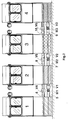
- the present invention consists in having separated the loop for mixing the bath from the several machines from the system used for normal dyeing machine running; i.e., in having used, for circulating the bath from a dyeing machine to another dyeing machine, a suitable pump of reversible type and having simply connected each tank to the tank of the immediately downstream dyeing machine by means of two pipes, wherein the one pipe is installed in a low position at tank bottom level, on which the pump and a valve are installed; and the other pipe being installed slightly under the maximal level reached by the dyeing bath inside the tank, and on which a second valve is installed.
- the circulation pump for the dyeing bath of each dyeing machine is used in this case only to circulate the dyeing bath inside the same machine, by collecting it from the bottom of the tank and supplying it, through the exchanger unit, to the Overflow funnel or Jet.
- the dyeing bath of each dyeing machine is collected by the pump from the bottom of the tank and is sent to the tank of the downstream dyeing machine, so that on this second machine the level of the dyeing bath contained in its tank rises and, through the second, higher-level pipe, overflows into the tank of the preceding dyeing machine, and so forth, according to the desired operating combinations, as it is disclosed in greater detail in the following.
- This procedure is performed during a certain time in a direction and is then reversed during a same time period, because the pumps are of reversible type.
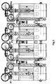
- (1), (2), (3) and (4) are the four machines which constitute the set of dyeing machines in question, suitable for operating in parallel.
- Each of them is equipped with a pump (P1), (P2), (P3) and (P4) which causes the dyeing bath of the respective machines to circulate, i.e., collects the dyeing bath from the tank bottom and delivers it, after flowing through the exchanger unit (S), to the Overflow funnel or Jet nozzle of each dyeing machine, in known way.
- P1 a pump
- P2 P2
- P3 the exchanger unit
- P4 which causes the dyeing bath of the respective machines to circulate, i.e., collects the dyeing bath from the tank bottom and delivers it, after flowing through the exchanger unit (S), to the Overflow funnel or Jet nozzle of each dyeing machine, in known way.
- the dyeing machine (1) is connected with the dyeing machine (2) by means of a pipe (5) installed at the level of the tank bottom portions of said dyeing machines, on which pipe (5), the pump (M1) and the valve (V1) are installed; and by a second pipe (6) positioned slightly under the maximal level which will be reached by the dyeing bath inside the tanks, and on which the valve (V4) is installed.
- the dyeing machine (2) is connected with the dyeing machine (3) by means of a pipe (7) installed at the level of their tank bottom portions, on which pipe (7) the pump (M2) and the valve (V2) are installed; and by a second pipe (8) positioned slightly under the maximal level which will be reached by the dyeing bath inside the tanks, and on which the valve (V5) is installed.
- the dyeing machine (3) is connected with the dyeing machine (4) by means of a pipe (9) installed at the level of the tank bottom portions of said dyeing machines, on which pipe (9), the pump (M3) and the valve (V3) are installed; and by a second pipe (10) positioned slightly under the maximal level which will be reached by the dyeing bath inside the tanks, and on which the valve (V6) is installed.
- the pumps (P1), (P2), (P3) and (P4) are kept operating as it normally occurs in Overflow or Jet dyeing machines operating on an individual basis, whereas the corresponding pumps (M1), (M2) and (M3), performing the task of homogenizing the dyeing bath by alternatively transferring it in both directions from each dyeing machine to the adjacent machine arranged in parallel to it, are caused to operate, or less according to the preselected parallel configuration as a function of the amount of fabric to be dyed into a determined colour.
- the present Applicant could find that according to this system, the dyeing bath contained inside a dyeing machine is caused to flow cyclically to another dyeing machine, and from each dyeing machine to all other dyeing machine, and a perfect homogenizing of the dyeing bath is thus obtained even in the case of a configuration with all machines being connected in parallel, with the dyeing bath being throughly mixed and with a surely homogeneous fabric dyeing being obtained.
- FIG 4 discloses the case when all machines operate on an individual basis.
- pumps (M1), (M2) and (M3) do not operate and valves (V1)-(V4), (V2)-(V5) and (V3)-(V6) are closed.
- FIG. 5 shows the case when dyeing machines (1) and (2) operate in parallel and machines (3) and (4) operate individually.
- valves (V1)-(V4) are open, all other valves are closed and pump (M1) is running.
- Figure 6 discloses the case when machine (1) and (2) operate individually and machines (3) and (4) operate in parallel. Consequently, in this case pumps (M1) and (M2) will be stationary, valves (V1)-(V2) and (V4)-(V5) will be closed, and valves (V3)-(V6) will be open and pump (M3) will be running.
- FIG. 7 shows the dyeing machines as being in a configuration of 2x2 in parallel.
- valves (V1)-(V4) will be open, pump (M1) will be running, valves (V2)-(V5) will be closed, pump (M2) will be running, valves (V3)-(V6) will be open and pump (M3) will be running.
- FIG 8 shows the machines (1), (2) and (3) as operating in parallel, with machine (4) operating individually.
- valves (V1)-(V4) and (V2)-(V5) are open, pumps (M1) and (M2) are running, valves (V3)-(V6) are closed and pump (M3) is stationary.
- Figure 9 shows all four machines as operating in parallel.
- the internal diameters of the pipes can be reduced because, while the dyeing bath from the upstream dyeing machine is flowing towards the immediately downstream dyeing machine, the dyeing bath from said immediately downstream dyeing machine is being simultaneously delivered back to the upstream dyeing machine owing to the effect of dyeing bath level increase.
- the electronic control system is much simpler, because it must control only 6 valves and 12 limit switches with a simple logics which must check only three well-defined combinations which are always the same.
Landscapes
- Engineering & Computer Science (AREA)
- Textile Engineering (AREA)
- Treatment Of Fiber Materials (AREA)
Priority Applications (3)
| Application Number | Priority Date | Filing Date | Title |
|---|---|---|---|
| EP19960107052 EP0806511B1 (de) | 1996-05-04 | 1996-05-04 | Für Einzel- oder Parallelbetrieb ausgerüstete Maschinen zum Färben von Textilien |
| ES96107052T ES2126350T3 (es) | 1996-05-04 | 1996-05-04 | Maquinas para teñir textiles por inmersion o por chorro montadas en serie o en paralelo. |
| DE1996600833 DE69600833T2 (de) | 1996-05-04 | 1996-05-04 | Für Einzel- oder Parallelbetrieb ausgerüstete Maschinen zum Färben von Textilien |
Applications Claiming Priority (1)
| Application Number | Priority Date | Filing Date | Title |
|---|---|---|---|
| EP19960107052 EP0806511B1 (de) | 1996-05-04 | 1996-05-04 | Für Einzel- oder Parallelbetrieb ausgerüstete Maschinen zum Färben von Textilien |
Publications (2)
| Publication Number | Publication Date |
|---|---|
| EP0806511A1 true EP0806511A1 (de) | 1997-11-12 |
| EP0806511B1 EP0806511B1 (de) | 1998-10-21 |
Family
ID=8222752
Family Applications (1)
| Application Number | Title | Priority Date | Filing Date |
|---|---|---|---|
| EP19960107052 Expired - Lifetime EP0806511B1 (de) | 1996-05-04 | 1996-05-04 | Für Einzel- oder Parallelbetrieb ausgerüstete Maschinen zum Färben von Textilien |
Country Status (3)
| Country | Link |
|---|---|
| EP (1) | EP0806511B1 (de) |
| DE (1) | DE69600833T2 (de) |
| ES (1) | ES2126350T3 (de) |
Cited By (3)
| Publication number | Priority date | Publication date | Assignee | Title |
|---|---|---|---|---|
| GB2404199A (en) * | 2003-07-25 | 2005-01-26 | Falmer Investment Ltd | Textile processing system |
| CN104790143A (zh) * | 2015-03-20 | 2015-07-22 | 殷翠萍 | 一种可控制染色程度的溢流染色机 |
| CN104947346A (zh) * | 2015-03-20 | 2015-09-30 | 殷翠萍 | 一种带复合式染色筒的溢流染色机 |
Citations (3)
| Publication number | Priority date | Publication date | Assignee | Title |
|---|---|---|---|---|
| JPS5959966A (ja) * | 1982-09-24 | 1984-04-05 | 日本染色機械株式会社 | 多槽式染色装置 |
| JPH0214065A (ja) * | 1988-06-29 | 1990-01-18 | Toyobo Co Ltd | 繊維品の処理装置 |
| US5228318A (en) * | 1992-01-24 | 1993-07-20 | Morton Machine Works, Inc. | Flow configuration for mixing dye |
-
1996
- 1996-05-04 DE DE1996600833 patent/DE69600833T2/de not_active Expired - Fee Related
- 1996-05-04 EP EP19960107052 patent/EP0806511B1/de not_active Expired - Lifetime
- 1996-05-04 ES ES96107052T patent/ES2126350T3/es not_active Expired - Lifetime
Patent Citations (3)
| Publication number | Priority date | Publication date | Assignee | Title |
|---|---|---|---|---|
| JPS5959966A (ja) * | 1982-09-24 | 1984-04-05 | 日本染色機械株式会社 | 多槽式染色装置 |
| JPH0214065A (ja) * | 1988-06-29 | 1990-01-18 | Toyobo Co Ltd | 繊維品の処理装置 |
| US5228318A (en) * | 1992-01-24 | 1993-07-20 | Morton Machine Works, Inc. | Flow configuration for mixing dye |
Non-Patent Citations (2)
| Title |
|---|
| DATABASE WPI Section Ch Week 8420, Derwent World Patents Index; Class F06, AN 84-123674, XP002015764 * |
| PATENT ABSTRACTS OF JAPAN vol. 14, no. 143 (C - 0703) 19 March 1990 (1990-03-19) * |
Cited By (5)
| Publication number | Priority date | Publication date | Assignee | Title |
|---|---|---|---|---|
| GB2404199A (en) * | 2003-07-25 | 2005-01-26 | Falmer Investment Ltd | Textile processing system |
| CN1295389C (zh) * | 2003-07-25 | 2007-01-17 | 科万商标投资有限公司 | 织物处理系统及织物处理机 |
| GB2404199B (en) * | 2003-07-25 | 2007-07-04 | Falmer Investment Ltd | Textile processing system |
| CN104790143A (zh) * | 2015-03-20 | 2015-07-22 | 殷翠萍 | 一种可控制染色程度的溢流染色机 |
| CN104947346A (zh) * | 2015-03-20 | 2015-09-30 | 殷翠萍 | 一种带复合式染色筒的溢流染色机 |
Also Published As
| Publication number | Publication date |
|---|---|
| EP0806511B1 (de) | 1998-10-21 |
| DE69600833D1 (de) | 1998-11-26 |
| ES2126350T3 (es) | 1999-03-16 |
| DE69600833T2 (de) | 1999-05-27 |
Similar Documents
| Publication | Publication Date | Title |
|---|---|---|
| CA1339908C (en) | Dye color control system | |
| EP0806511A1 (de) | Für Einzel- oder Parallelbetrieb ausgerüstete Maschinen zum Färben von Textilien | |
| KR920003943B1 (ko) | 분무 염색시 염료 색깔을 연속 교체하는 방법 | |
| CA2292906C (en) | Device for applying a fluid processing agent to a strip of fabric | |
| US4960139A (en) | Water flow distributor for a washing machine | |
| EP0976861A1 (de) | Vorrichtung und Verfahren zur Versorgung von Maschinen mit Farbflotten für die kontinuierliche Färbung von Textilien | |
| DE4107478C1 (de) | ||
| JP2673701B2 (ja) | 繊維品の処理装置 | |
| US6314771B1 (en) | Device for applying a patterning agent to a line | |
| CN110373843B (zh) | 平幅连续联合水洗机 | |
| US3751223A (en) | Method for treating textile material with a liquid | |
| US4710993A (en) | Dye color control system | |
| US4727611A (en) | Apparatus and method for dyeing yarns | |
| PL97089B1 (pl) | Urzadzenie do natryskowego drukowania tkanin,zwlaszcza dywanow | |
| EP3987103B1 (de) | Maschine und verfahren zum diskontinuierlichen färben von garnspulen | |
| CN219692582U (zh) | 一种染色助剂输送阀组阵列结构 | |
| US5335516A (en) | Dyeing machine | |
| JPH01282380A (ja) | 連結式パッケージ染色装置 | |
| DE3346690A1 (de) | Durchlaufwaschmaschine | |
| CN216618074U (zh) | 一种控制多单速马达的液压回路及供油系统 | |
| CN207933673U (zh) | 一种双泵单筒纱线双向染色机构 | |
| US5787733A (en) | Treatment machine, in particular for textiles, comprising a removable vat and a fixed terminal installation | |
| CN109208207B (zh) | 一种降低染色色差的装置及工艺 | |
| GB1576405A (en) | Process and an apparatus for the wet treatment of endless strand-form textile material | |
| CN2419230Y (zh) | 消除卷染机深浅边的装置 |
Legal Events
| Date | Code | Title | Description |
|---|---|---|---|
| PUAI | Public reference made under article 153(3) epc to a published international application that has entered the european phase |
Free format text: ORIGINAL CODE: 0009012 |
|
| 17P | Request for examination filed |
Effective date: 19970201 |
|
| AK | Designated contracting states |
Kind code of ref document: A1 Designated state(s): CH DE ES FR GB GR IT LI PT |
|
| GRAG | Despatch of communication of intention to grant |
Free format text: ORIGINAL CODE: EPIDOS AGRA |
|
| GRAG | Despatch of communication of intention to grant |
Free format text: ORIGINAL CODE: EPIDOS AGRA |
|
| GRAH | Despatch of communication of intention to grant a patent |
Free format text: ORIGINAL CODE: EPIDOS IGRA |
|
| 17Q | First examination report despatched |
Effective date: 19980319 |
|
| GRAH | Despatch of communication of intention to grant a patent |
Free format text: ORIGINAL CODE: EPIDOS IGRA |
|
| GRAA | (expected) grant |
Free format text: ORIGINAL CODE: 0009210 |
|
| AK | Designated contracting states |
Kind code of ref document: B1 Designated state(s): CH DE ES FR GB GR IT LI PT |
|
| REG | Reference to a national code |
Ref country code: CH Ref legal event code: EP |
|
| REF | Corresponds to: |
Ref document number: 69600833 Country of ref document: DE Date of ref document: 19981126 |
|
| 29U | Proceedings interrupted after grant according to rule 142 epc |
Effective date: 19980918 |
|
| 29W | Proceedings resumed after grant [after interruption of proceedings according to rule 142 epc] |
Effective date: 19981204 |
|
| REG | Reference to a national code |
Ref country code: CH Ref legal event code: NV Representative=s name: PATENTANWAELTE SCHAAD, BALASS, MENZL & PARTNER AG |
|
| ET | Fr: translation filed | ||
| REG | Reference to a national code |
Ref country code: ES Ref legal event code: FG2A Ref document number: 2126350 Country of ref document: ES Kind code of ref document: T3 |
|
| REG | Reference to a national code |
Ref country code: PT Ref legal event code: SC4A Free format text: AVAILABILITY OF NATIONAL TRANSLATION Effective date: 19981221 |
|
| PLBE | No opposition filed within time limit |
Free format text: ORIGINAL CODE: 0009261 |
|
| STAA | Information on the status of an ep patent application or granted ep patent |
Free format text: STATUS: NO OPPOSITION FILED WITHIN TIME LIMIT |
|
| 26N | No opposition filed | ||
| REG | Reference to a national code |
Ref country code: GB Ref legal event code: IF02 |
|
| PGFP | Annual fee paid to national office [announced via postgrant information from national office to epo] |
Ref country code: GB Payment date: 20060503 Year of fee payment: 11 |
|
| PGFP | Annual fee paid to national office [announced via postgrant information from national office to epo] |
Ref country code: PT Payment date: 20060505 Year of fee payment: 11 |
|
| PGFP | Annual fee paid to national office [announced via postgrant information from national office to epo] |
Ref country code: GR Payment date: 20060511 Year of fee payment: 11 Ref country code: DE Payment date: 20060511 Year of fee payment: 11 |
|
| PGFP | Annual fee paid to national office [announced via postgrant information from national office to epo] |
Ref country code: FR Payment date: 20060515 Year of fee payment: 11 Ref country code: CH Payment date: 20060515 Year of fee payment: 11 |
|
| PGFP | Annual fee paid to national office [announced via postgrant information from national office to epo] |
Ref country code: ES Payment date: 20060621 Year of fee payment: 11 |
|
| REG | Reference to a national code |
Ref country code: PT Ref legal event code: MM4A Free format text: LAPSE DUE TO NON-PAYMENT OF FEES Effective date: 20071105 |
|
| REG | Reference to a national code |
Ref country code: CH Ref legal event code: PL |
|
| GBPC | Gb: european patent ceased through non-payment of renewal fee |
Effective date: 20070504 |
|
| PG25 | Lapsed in a contracting state [announced via postgrant information from national office to epo] |
Ref country code: PT Free format text: LAPSE BECAUSE OF NON-PAYMENT OF DUE FEES Effective date: 20071105 |
|
| PG25 | Lapsed in a contracting state [announced via postgrant information from national office to epo] |
Ref country code: LI Free format text: LAPSE BECAUSE OF NON-PAYMENT OF DUE FEES Effective date: 20070531 Ref country code: CH Free format text: LAPSE BECAUSE OF NON-PAYMENT OF DUE FEES Effective date: 20070531 |
|
| REG | Reference to a national code |
Ref country code: FR Ref legal event code: ST Effective date: 20080131 |
|
| PG25 | Lapsed in a contracting state [announced via postgrant information from national office to epo] |
Ref country code: DE Free format text: LAPSE BECAUSE OF NON-PAYMENT OF DUE FEES Effective date: 20071201 |
|
| PG25 | Lapsed in a contracting state [announced via postgrant information from national office to epo] |
Ref country code: GB Free format text: LAPSE BECAUSE OF NON-PAYMENT OF DUE FEES Effective date: 20070504 |
|
| PG25 | Lapsed in a contracting state [announced via postgrant information from national office to epo] |
Ref country code: FR Free format text: LAPSE BECAUSE OF NON-PAYMENT OF DUE FEES Effective date: 20070531 |
|
| REG | Reference to a national code |
Ref country code: ES Ref legal event code: FD2A Effective date: 20070505 |
|
| PGFP | Annual fee paid to national office [announced via postgrant information from national office to epo] |
Ref country code: IT Payment date: 20080530 Year of fee payment: 13 |
|
| PG25 | Lapsed in a contracting state [announced via postgrant information from national office to epo] |
Ref country code: GR Free format text: LAPSE BECAUSE OF NON-PAYMENT OF DUE FEES Effective date: 20071204 Ref country code: ES Free format text: LAPSE BECAUSE OF NON-PAYMENT OF DUE FEES Effective date: 20070505 |
|
| PG25 | Lapsed in a contracting state [announced via postgrant information from national office to epo] |
Ref country code: IT Free format text: LAPSE BECAUSE OF NON-PAYMENT OF DUE FEES Effective date: 20090504 |