EP0806467B1 - Verfahren und Einrichtung zur thermischen Umsetzung von Kohlenwasserstoffen zu ungesättigten aliphatischen Kohlenwasserstoffen durch Kombination einer Dampfkrackung und einer Pyrolysestufe - Google Patents
Verfahren und Einrichtung zur thermischen Umsetzung von Kohlenwasserstoffen zu ungesättigten aliphatischen Kohlenwasserstoffen durch Kombination einer Dampfkrackung und einer Pyrolysestufe Download PDFInfo
- Publication number
- EP0806467B1 EP0806467B1 EP97400998A EP97400998A EP0806467B1 EP 0806467 B1 EP0806467 B1 EP 0806467B1 EP 97400998 A EP97400998 A EP 97400998A EP 97400998 A EP97400998 A EP 97400998A EP 0806467 B1 EP0806467 B1 EP 0806467B1
- Authority
- EP
- European Patent Office
- Prior art keywords
- steam
- zone
- decoking
- pyrolysis
- steam cracking
- Prior art date
- Legal status (The legal status is an assumption and is not a legal conclusion. Google has not performed a legal analysis and makes no representation as to the accuracy of the status listed.)
- Expired - Lifetime
Links
- 238000000197 pyrolysis Methods 0.000 title claims description 83
- 238000004230 steam cracking Methods 0.000 title claims description 59
- 150000002430 hydrocarbons Chemical class 0.000 title claims description 44
- 229930195733 hydrocarbon Natural products 0.000 title claims description 43
- 238000000034 method Methods 0.000 title claims description 24
- 238000006243 chemical reaction Methods 0.000 title claims description 22
- 150000001338 aliphatic hydrocarbons Chemical class 0.000 title description 2
- 238000005235 decoking Methods 0.000 claims description 65
- 238000010438 heat treatment Methods 0.000 claims description 47
- OTMSDBZUPAUEDD-UHFFFAOYSA-N Ethane Chemical compound CC OTMSDBZUPAUEDD-UHFFFAOYSA-N 0.000 claims description 17
- 239000000571 coke Substances 0.000 claims description 15
- 239000004215 Carbon black (E152) Substances 0.000 claims description 14
- 238000001816 cooling Methods 0.000 claims description 10
- 229910010293 ceramic material Inorganic materials 0.000 claims description 7
- 239000011819 refractory material Substances 0.000 claims description 6
- 125000004432 carbon atom Chemical group C* 0.000 claims description 5
- 239000012530 fluid Substances 0.000 claims description 3
- 230000001105 regulatory effect Effects 0.000 claims description 3
- 150000001875 compounds Chemical class 0.000 claims description 2
- 230000003213 activating effect Effects 0.000 claims 1
- XLYOFNOQVPJJNP-UHFFFAOYSA-N water Substances O XLYOFNOQVPJJNP-UHFFFAOYSA-N 0.000 description 41
- 239000007789 gas Substances 0.000 description 18
- 239000000203 mixture Substances 0.000 description 11
- VGGSQFUCUMXWEO-UHFFFAOYSA-N Ethene Chemical compound C=C VGGSQFUCUMXWEO-UHFFFAOYSA-N 0.000 description 9
- 238000010791 quenching Methods 0.000 description 9
- 239000005977 Ethylene Substances 0.000 description 7
- HSFWRNGVRCDJHI-UHFFFAOYSA-N alpha-acetylene Natural products C#C HSFWRNGVRCDJHI-UHFFFAOYSA-N 0.000 description 7
- 239000001257 hydrogen Substances 0.000 description 7
- 229910052739 hydrogen Inorganic materials 0.000 description 7
- 230000000171 quenching effect Effects 0.000 description 7
- 125000002534 ethynyl group Chemical group [H]C#C* 0.000 description 6
- 238000005192 partition Methods 0.000 description 6
- UFHFLCQGNIYNRP-UHFFFAOYSA-N Hydrogen Chemical compound [H][H] UFHFLCQGNIYNRP-UHFFFAOYSA-N 0.000 description 5
- UGFAIRIUMAVXCW-UHFFFAOYSA-N Carbon monoxide Chemical compound [O+]#[C-] UGFAIRIUMAVXCW-UHFFFAOYSA-N 0.000 description 4
- 229910002091 carbon monoxide Inorganic materials 0.000 description 4
- 239000000919 ceramic Substances 0.000 description 4
- -1 acetylene compound Chemical class 0.000 description 3
- 230000008901 benefit Effects 0.000 description 3
- 239000011261 inert gas Substances 0.000 description 3
- 239000000463 material Substances 0.000 description 3
- 239000003921 oil Substances 0.000 description 3
- IJGRMHOSHXDMSA-UHFFFAOYSA-N Atomic nitrogen Chemical compound N#N IJGRMHOSHXDMSA-UHFFFAOYSA-N 0.000 description 2
- KAKZBPTYRLMSJV-UHFFFAOYSA-N Butadiene Chemical compound C=CC=C KAKZBPTYRLMSJV-UHFFFAOYSA-N 0.000 description 2
- 150000001335 aliphatic alkanes Chemical class 0.000 description 2
- 229910052799 carbon Inorganic materials 0.000 description 2
- 238000000151 deposition Methods 0.000 description 2
- 238000004821 distillation Methods 0.000 description 2
- 150000002431 hydrogen Chemical class 0.000 description 2
- 238000009434 installation Methods 0.000 description 2
- 229910052751 metal Inorganic materials 0.000 description 2
- 239000002184 metal Substances 0.000 description 2
- 238000007789 sealing Methods 0.000 description 2
- HBMJWWWQQXIZIP-UHFFFAOYSA-N silicon carbide Chemical compound [Si+]#[C-] HBMJWWWQQXIZIP-UHFFFAOYSA-N 0.000 description 2
- 229910010271 silicon carbide Inorganic materials 0.000 description 2
- 229930195735 unsaturated hydrocarbon Natural products 0.000 description 2
- QQONPFPTGQHPMA-UHFFFAOYSA-N Propene Chemical compound CC=C QQONPFPTGQHPMA-UHFFFAOYSA-N 0.000 description 1
- 238000004616 Pyrometry Methods 0.000 description 1
- 229910052581 Si3N4 Inorganic materials 0.000 description 1
- 241001080024 Telles Species 0.000 description 1
- 150000001336 alkenes Chemical class 0.000 description 1
- QVGXLLKOCUKJST-UHFFFAOYSA-N atomic oxygen Chemical compound [O] QVGXLLKOCUKJST-UHFFFAOYSA-N 0.000 description 1
- 230000004888 barrier function Effects 0.000 description 1
- 230000015556 catabolic process Effects 0.000 description 1
- 238000004523 catalytic cracking Methods 0.000 description 1
- 238000005253 cladding Methods 0.000 description 1
- 230000000052 comparative effect Effects 0.000 description 1
- 238000010924 continuous production Methods 0.000 description 1
- 229910052878 cordierite Inorganic materials 0.000 description 1
- 238000006731 degradation reaction Methods 0.000 description 1
- 230000008021 deposition Effects 0.000 description 1
- 238000010790 dilution Methods 0.000 description 1
- 239000012895 dilution Substances 0.000 description 1
- JSKIRARMQDRGJZ-UHFFFAOYSA-N dimagnesium dioxido-bis[(1-oxido-3-oxo-2,4,6,8,9-pentaoxa-1,3-disila-5,7-dialuminabicyclo[3.3.1]nonan-7-yl)oxy]silane Chemical compound [Mg++].[Mg++].[O-][Si]([O-])(O[Al]1O[Al]2O[Si](=O)O[Si]([O-])(O1)O2)O[Al]1O[Al]2O[Si](=O)O[Si]([O-])(O1)O2 JSKIRARMQDRGJZ-UHFFFAOYSA-N 0.000 description 1
- KZHJGOXRZJKJNY-UHFFFAOYSA-N dioxosilane;oxo(oxoalumanyloxy)alumane Chemical compound O=[Si]=O.O=[Si]=O.O=[Al]O[Al]=O.O=[Al]O[Al]=O.O=[Al]O[Al]=O KZHJGOXRZJKJNY-UHFFFAOYSA-N 0.000 description 1
- 230000008034 disappearance Effects 0.000 description 1
- 238000005485 electric heating Methods 0.000 description 1
- UVGCAWDXQWPTEK-UHFFFAOYSA-N ethane;hydrate Chemical compound O.CC UVGCAWDXQWPTEK-UHFFFAOYSA-N 0.000 description 1
- 239000000945 filler Substances 0.000 description 1
- 229910052863 mullite Inorganic materials 0.000 description 1
- 229910052757 nitrogen Inorganic materials 0.000 description 1
- 238000013021 overheating Methods 0.000 description 1
- 230000001590 oxidative effect Effects 0.000 description 1
- 239000001301 oxygen Substances 0.000 description 1
- 229910052760 oxygen Inorganic materials 0.000 description 1
- 239000003208 petroleum Substances 0.000 description 1
- 230000002035 prolonged effect Effects 0.000 description 1
- MWWATHDPGQKSAR-UHFFFAOYSA-N propyne Chemical group CC#C MWWATHDPGQKSAR-UHFFFAOYSA-N 0.000 description 1
- 238000010926 purge Methods 0.000 description 1
- 239000000523 sample Substances 0.000 description 1
- 229920006395 saturated elastomer Polymers 0.000 description 1
- 238000000926 separation method Methods 0.000 description 1
- 238000007086 side reaction Methods 0.000 description 1
- 229910052710 silicon Inorganic materials 0.000 description 1
- 239000010703 silicon Substances 0.000 description 1
- HQVNEWCFYHHQES-UHFFFAOYSA-N silicon nitride Chemical compound N12[Si]34N5[Si]62N3[Si]51N64 HQVNEWCFYHHQES-UHFFFAOYSA-N 0.000 description 1
- 238000002352 steam pyrolysis Methods 0.000 description 1
- 230000008646 thermal stress Effects 0.000 description 1
- 230000009466 transformation Effects 0.000 description 1
- 238000011282 treatment Methods 0.000 description 1
- 238000011144 upstream manufacturing Methods 0.000 description 1
Images
Classifications
-
- C—CHEMISTRY; METALLURGY
- C10—PETROLEUM, GAS OR COKE INDUSTRIES; TECHNICAL GASES CONTAINING CARBON MONOXIDE; FUELS; LUBRICANTS; PEAT
- C10G—CRACKING HYDROCARBON OILS; PRODUCTION OF LIQUID HYDROCARBON MIXTURES, e.g. BY DESTRUCTIVE HYDROGENATION, OLIGOMERISATION, POLYMERISATION; RECOVERY OF HYDROCARBON OILS FROM OIL-SHALE, OIL-SAND, OR GASES; REFINING MIXTURES MAINLY CONSISTING OF HYDROCARBONS; REFORMING OF NAPHTHA; MINERAL WAXES
- C10G51/00—Treatment of hydrocarbon oils, in the absence of hydrogen, by two or more cracking processes only
- C10G51/02—Treatment of hydrocarbon oils, in the absence of hydrogen, by two or more cracking processes only plural serial stages only
- C10G51/023—Treatment of hydrocarbon oils, in the absence of hydrogen, by two or more cracking processes only plural serial stages only only thermal cracking steps
-
- C—CHEMISTRY; METALLURGY
- C10—PETROLEUM, GAS OR COKE INDUSTRIES; TECHNICAL GASES CONTAINING CARBON MONOXIDE; FUELS; LUBRICANTS; PEAT
- C10G—CRACKING HYDROCARBON OILS; PRODUCTION OF LIQUID HYDROCARBON MIXTURES, e.g. BY DESTRUCTIVE HYDROGENATION, OLIGOMERISATION, POLYMERISATION; RECOVERY OF HYDROCARBON OILS FROM OIL-SHALE, OIL-SAND, OR GASES; REFINING MIXTURES MAINLY CONSISTING OF HYDROCARBONS; REFORMING OF NAPHTHA; MINERAL WAXES
- C10G9/00—Thermal non-catalytic cracking, in the absence of hydrogen, of hydrocarbon oils
- C10G9/14—Thermal non-catalytic cracking, in the absence of hydrogen, of hydrocarbon oils in pipes or coils with or without auxiliary means, e.g. digesters, soaking drums, expansion means
- C10G9/16—Preventing or removing incrustation
-
- Y—GENERAL TAGGING OF NEW TECHNOLOGICAL DEVELOPMENTS; GENERAL TAGGING OF CROSS-SECTIONAL TECHNOLOGIES SPANNING OVER SEVERAL SECTIONS OF THE IPC; TECHNICAL SUBJECTS COVERED BY FORMER USPC CROSS-REFERENCE ART COLLECTIONS [XRACs] AND DIGESTS
- Y10—TECHNICAL SUBJECTS COVERED BY FORMER USPC
- Y10S—TECHNICAL SUBJECTS COVERED BY FORMER USPC CROSS-REFERENCE ART COLLECTIONS [XRACs] AND DIGESTS
- Y10S585/00—Chemistry of hydrocarbon compounds
- Y10S585/949—Miscellaneous considerations
- Y10S585/95—Prevention or removal of corrosion or solid deposits
Definitions
- the invention relates to a process for pyrolysis of a hydrocarbon feedstock with at least two carbon atoms and simultaneously a process for decoking the coke deposited on the walls of the reactor.
- pyrolysis reactors made of ceramic material have been used in which non-watertight partitions advantageously made of ceramic material determine channels where the charge and the reaction effluents circulate.
- These partitions advantageously have a shape adapted to create turbulence and include, for example, cells or cavities in the level of heating means. These are usually ducts containing a heater electric or a gas burner.
- Another drawback is related to the frequency of decoking of the tubes, every two or three month. Indeed, at the end of the cycle, the inside of the tubes is covered with a thick layer of coke. Coke may come off at times and is entrained by the gas flow to speeds of the order of 200 m / s risking damage to the ceramic sheaths of the pyrolysis oven downstream of the steam cracking oven.
- An object of the invention is to provide a method for pyrolyzing a charge hydrocarbon without stopping the unit while allowing decoking of this unit.
- Another object is to reduce the investment and operating costs of the unit.
- Another object of the invention is to maintain the temperature of the installation substantially constant during its walk, to avoid thermal stresses which would not fail to occur, especially when using an oxygen-containing gas for the stage of decoking which implements an exothermic reaction while the pyrolysis step puts in performs an endothermic reaction.
- the invention relates to a pyrolysis and decoking process in continuous in a reaction zone comprising a pyrolysis zone (40) made of material refractory, elongated in a direction (an axis) having a heating zone and a cooling zone following the heating zone, the heating zone comprising at least two rows (1, 2) substantially parallel to the axis, separated by a partition (70), advantageously not watertight, of refractory material between two rows successive, at least one of said rows (1) receiving hydrocarbons and steam of water, at least one other (2) of said rows essentially receiving water vapor, said rows comprising heating means (8) surrounded by sheaths (7) substantially parallel to each other and substantially perpendicular to the axis of the reactor, coke depositing in the reaction zone, the process being characterized in that a charge is circulated hydrocarbon containing at least one hydrocarbon with at least two carbon atoms to an adequate steam cracking temperature in a steam cracking zone containing at least at least two steam cracking tubes, at least two
- the exit temperature from the steam cracking zone is generally lower than the outlet temperature of the zone heating zone pyrolysis.
- the temperature in the steam cracking tube (s) where the steam cracking takes place the charge is advantageously maintained substantially equal to the temperature in the tubes where decoking takes place.
- the temperature in the row or rows where the pyrolysis of the gas stream leaving the steam cracking zone is advantageously maintained approximately equal to the temperature in the row or rows where the decoking.
- the outlet temperature of the heating zone relative to hydrocarbons and the exit temperature from the heating relative to the decoking effluent are about 1000 to 1400 ° C.
- the amount of water vapor introduced into the zone of steam cracking, compared to that of the charge, in other words the steam weight ratio of water on charge, for a determined charge is greater than that corresponding to a conventional steam cracking of the same charge.
- this ratio is greater than 0.5 while it is usually around 0.2.
- the ratio is higher at 0.7 while it is usually around 0.5.
- the ratio is greater than 1, for example equal to 2 whereas it is usually close to 1.
- the choice of a high water vapor to charge ratio has the advantage of reducing the coke deposit. It will not be able to grow significantly since it is planned to decoker every four or five days for example, that is to say at a frequency corresponding to that of decoking the pyrolysis reactor, instead of decoking both at three months in the case of industrial steam crackers.
- the steam cracker being connected to the pyrolysis furnace by a very short pipe, there is has practically no dead volume whereas when using the effluent from a steam cracker industrial as a pyrolysis reactor charge, having to cool the gas in a heat exchanger creates a large dead volume where secondary products are formed undesirable, by high temperature degradation of ethylene and acetylene.
- the hydrocarbon supply in the tube is cut intended to be decoked and the flow of water introduced is substantially increased so as not to not cause excessive thermal disturbance in the gas preheating furnace upstream of the steam cracking zone.
- the steam cracking furnace is usually heated by conventional gas burners, type radiant burners.
- the load is generally preheated between 300 and 400 ° C.
- the the temperature of the steam cracking zone is usually at most equal to 900 ° C.
- the heating means of the pyrolysis reactor can be electrical resistances contained in sheaths as described in the above patents or they may be consisting of sheaths containing a gas burner as described in the patent application of the Applicant (FR 2715583).
- Each row may include at least one layer of heating means surrounded by sheaths, substantially parallel to the axis of the reaction zone, these sheaths being substantially perpendicular to said axis.
- heating elements either electric or comprising burners with gases, their number, the distance between them and their configuration are described in the patents cited above.
- a cladding gas containing hydrogen and / or water vapor and / or carbon monoxide and / or an inert gas could be used and could also diffuse inside to outside of the sheaths without disturbing the pyrolysis reaction and without disturbing the decoking reaction.
- the hydrocarbons collected and the decoking effluent can be mixed before being introduced into the cooling zone.
- the hydrocarbons collected and the decoking effluent are cooled separately in their respective rows, located at the level of the cooling, then possibly mixed.
- the cooling zone is usually a zone of direct quenching by a cooling, known to those skilled in the art, advantageously followed by a heat exchanger indirect contact generating steam (TLE: transfer line exchanger).
- TLE transfer line exchanger
- the installation has the advantage of being safe, reliable and easy to implement. She uses in the pyrolysis zone, refractory materials and more particularly materials ceramics known to those skilled in the art such as cordierite, mullite, silicon nitride or silicon carbide.
- the invention also relates to a continuous pyrolysis and decoking unit for setting up work in particular of the process according to the invention, comprising a reactor (40) for pyrolysis of elongated shape in a direction (an axis) comprising at least two rows (1, 2) substantially parallel to the axis separated by a partition, (70) advantageously not sealed, of refractory material between two successive rows, each row comprising a plurality of heating means (8) arranged in at least one layer of heating elements surrounded by sheaths (7) of ceramic material substantially parallel to each other and substantially perpendicular to the axis of the reactor, at least one of the rows (1) being adapted to receive hydrocarbons and water vapor, at least one other (2) of said rows being adapted to receive water vapor, said pyrolysis reactor comprising heating control and modulation means connected to the heating means, the pyrolysis reactor further comprising means (47) for cooling the effluents products in each row, said unit being characterized in that it comprises a steam cracking reactor
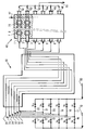
- Hydrocarbon supply lines 11, 12, 13, 14, 15, 16 controlled respectively by valves V1, V2, V3, V4, V5 and V6 introduce into a steam cracker 30 then into a reactor 40 for pyrolysis and decoking of hydrocarbons, for example ethane, from a line 10 mixed with water generally in vapor form provided by a line 60.
- This line distributes it in lines 17, 18, 19, 20, 21 and 22 controlled respectively by valves V7, V8, V9, V10, V11 and V12.
- valves V1 to V12 are adapted to allow the circulation of a mixture of hydrocarbons and water vapor in a certain number of tubes of the steam cracker 30 and of adjacent rows of the so-called pyrolysis reactor 40 and only of water vapor in other steam cracker 30 tubes and other adjacent rows of the so-called decoking reactor 40 for removing the coke which has been deposited during the steam cracking and pyrolysis reaction respectively.
- Steam cracker tubes 31, 32, 33, 34, 35, 36 transporting the mixture of hydrocarbons and water or transporting water alone, connected respectively to lines 11 and 22, 12 and 21, 13 and 20, 14 and 19, 15 and 18 and finally, 16 and 17, are heated in the steam cracker 30 to a temperature of 850 to 900 ° C so as to crack part of the hydrocarbon charge and are connected respectively to rows 1, 2, 3, 4 , 5 and 6 of the pyrolysis reactor 40.
- valve V1 closing the line 11
- the tube 31 receives only the water vapor supplied by line 22 controlled by valve V12.
- the tubes 32, 33, 34, 35 and 36 receive the hydrocarbon and water mixture, all the other valves mentioned being open.
- All the tubes are preheated to around 400 ° C, essentially by convective heating in the first part of the heating oven, then at around 900 ° C in the second part of oven, essentially by radiative heating, by means of a plurality of burners.
- the steam cracking effluent is introduced into the pyrolysis reactor 40 by lines of very short junction, not performing the function of quenching.
- the pyrolysis reactor 40 adjacent to the steam cracking reactor 30 is divided into rows longitudinal (1, 2, 3, 4, 5 and 6) substantially parallel to its axis. These rows are separate from each other by partitions, 70, not leaktight in ceramic material, of shape comprising cells adapted to promote turbulence inside the row and therefore to favor the reaction. These rows contain sheaths of ceramic material 7 forming a sheet substantially parallel to the axis of the reactor. These sheaths are substantially parallel between them and substantially perpendicular to the axis of the reactor. They contain, for example, a plurality of electrical resistors 8 bathed in a sheath gas, chosen in the group formed by water vapor, hydrogen, carbon monoxide, an inert gas and a mixture of two or more of these gases.
- the tube 31 containing water vapor is connected by a shortest heated line possible with row 1 of reactor 40.
- the water vapor flow rate is increased inserted in the tube and in the row where decoking takes place, for example 2 to 3 times that used in the other tubes 32, 33, 34, 35 and the other rows 2, 3, 4, 5 and 6 where the pyrolysis.
- the outlet temperature of the pyrolysis reactor 40 is heated to around 1200 ° C.
- the terminal part of the various rows of reactor 40 intended for pyrolysis or for decoking, receives the pyrolysis or decoking effluents and each row is connected to a direct quenching line 47, comprising a controlled flow injector, for example of ethane if the charge is ethane, which allows these effluents to be cooled.
- a direct quenching line 47 comprising a controlled flow injector, for example of ethane if the charge is ethane, which allows these effluents to be cooled.
- lines 41, 42, 43, 44, 45 and 46 respectively connected to rows 1, 2, 3, 4, 5 and 6 mix the various effluents which are discharged through a line 50.
- the effluents can be cooled by circulating through watertight conduits arranged in the end part of the rows by indirect quenching, then mixed as described above.
- the pyrolysis and decoking effluents from rows 1, 2, 3, 4, 5 and 6 are collected by lines 41, 42, 43, 44, 45 and 46, then mixed and sent in a direct or indirect quenching zone and once cooled evacuated by line 50.
- the heating elements 8 of the pyrolysis reactor are supplied with electrical energy from independently thanks to a pair of electrodes not shown in the figure, probes thermocouple pyrometry not shown are housed in the spaces where the charge and allow to automatically regulate the temperature of each section of heating, by a conventional regulation and modulation device not shown on the figure, depending on the temperature profile chosen which applies equally well to the reaction of pyrolysis than that of decoking the walls of the sheaths.
- a temperature regulation device which may be the same, also makes it possible to control the temperature of the steam cracking reactor burners so that this temperature is lower than the outlet temperature of the oil collected and the final decoking effluent from the pyrolysis reactor.
- a steam cracker-pyrolysis reactor assembly described according to FIG. 1 is used to crack a mixture of ethane and water vapor to produce a mixture of ethylene and acetylene.
- the weight ratio of water vapor to ethane is 1.8.
- the mixture (ethane-water) and the decoking vapor are brought to 900 ° C. in the reactor 30 steam cracking and heated in a substantially linear manner up to 1200 ° C in the pyrolysis reactor at an absolute pressure of 1.3 bar.
- the steam cracker has six heating tubes.
- the pyrolysis reactor has six heating rows substantially parallel to its axis and separated by partitions in the form of cells and ceramic material such as carbide silicon for example. Each row includes a tablecloth parallel to the axis of elements electric heaters.
- the ducts perpendicular to the axis of the reactor, surrounding the electrical resistors are made of silicon carbide and contain a sheath gas which is nitrogen.
- decoking is checked by disappearance of carbon monoxide, which is analyzed online by infrared, for example at the outlet of the pyrolysis oven. It is found that decoking is almost complete after 14 hours in each tube and row where it is carried out and we immediately go back into a steam cracking reaction situation for the tube which has been decoked and pyrolysis for the row which has been decoked.
- An industrial steam cracker effluent is used as the pyrolysis hydrocarbon charge.
- ethane having operated at a temperature of 900 ° C, this effluent being cooled by quenching indirect at 450 ° C.
- This charge, introduced by line 10, is divided between five lines (n ° 11, 13, 14, 15 and 16) corresponding as for the example above to the five working rows in pyrolysis (n ° 1, 3, 4, 5 and 6).
- each row of the pyrolysis zone 258 kg / h of hydrocarbons are introduced and of hydrogen and 86 kg / h of water from the conventional steam cracker and by each line 17, 18, 19, 20 or 22, 378 kg / h of water.
- valve V2 of hydrocarbons In row 2 of the pyrolysis zone operating in decoking, the valve V2 of hydrocarbons being closed, 979 kg / h of water vapor is sent through valve V11 and line 21.
Landscapes
- Chemical & Material Sciences (AREA)
- Oil, Petroleum & Natural Gas (AREA)
- Physics & Mathematics (AREA)
- Thermal Sciences (AREA)
- Engineering & Computer Science (AREA)
- Chemical Kinetics & Catalysis (AREA)
- General Chemical & Material Sciences (AREA)
- Organic Chemistry (AREA)
- Production Of Liquid Hydrocarbon Mixture For Refining Petroleum (AREA)
- Organic Low-Molecular-Weight Compounds And Preparation Thereof (AREA)
- Feeding, Discharge, Calcimining, Fusing, And Gas-Generation Devices (AREA)
Claims (13)
- Verfahren zur kontinuierlichen Pyrolyse und Entkokung in einer Reaktionszone, welche eine Pyrolysezone (40) aus feuerfestem Material, die gemäß einer Richtung (Achse) länglich ist, umfasst und über eine Heizzone und eine Kühlzone im Anschluss an die Heizzone verfügt, wobei die Heizzone wenigstens zwei im wesentlichen parallel zur Achse liegende Reihen (1,2) umfasst, welche durch eine Trennwand (70) aus einem feuerfesten Material zwischen zwei aufeinander folgenden Reihen getrennt sind, wenigstens eine dieser Reihen (1) Kohlenwasserstoffe und Wasserdampf aufnimmt, wenigstens eine andere (2) dieser Reihen im wesentlichen Wasserdampf aufnimmt, wobei diese Reihen Heizmittel (8), umgeben von Hüllen (7), umfassen, die im wesentlichen parallel untereinander und im wesentlichen senkrecht zur Achse des Reaktors sind, wobei sich Koks in der Reaktionszone abscheidet, dadurch gekennzeichnet, dass man eine kohlenwasserstoffhaltige einen Kohlenwasserstoff mit wenigstens zwei Kohlenwasserstoffatomen enthaltende Charge bei einer Temperatur, die für Dampfcracken adäquat ist, in einer Dampfcrackzone, welche über wenigstens zwei Dampfcrackrohre verfügt, zirkulieren lässt, wobei wenigstens eines dieser Rohre mit einer Speisung an Charge und an Wasserdampf in Verbindung steht und derart erwärmt wird, dass die Charge gecrackt wird und wenigstens ein anderes dieser Rohre mit einer Speisung mit einem im wesentlichen aus Wasserdampf bestehenden Fluid in Verbindung steht und derart erwärmt wird, dass dieses Rohr, auf dem der Koks abgeschieden ist, entkokt wird; der Wasserdampfdurchsatz im Dampfcrackrohr derart ist, dass das Gewichtsverhältnis von Waserdampf/-Charge zwischen 0,5 und 20 liegt und man einen Dampfcrackgasstrom erhält, welcher die Kohlenwasserstoffe und Wasserdampf umfasst sowie einen Entkokungsgasstrom, der im wesentlichen Wasserdampf umfasst und dass man diesen Dampfcrackstrom in wenigstens einer Reihe dieser Heizzone der Pyrolysezone (40), welche der Dampfcrackzone benachbart ist, zirkulieren lässt, derart, dass der Dampfcrackstrom pyrolysiert wird und sich eine Temperatur am Austritt der Heizzone von wenigstens 850°C ergibt, und man den Entkokungsstrom in wenigstens der anderen Reihe der Heizzone derart zirkulieren lässt, dass wenigstens zum Teil diese Reihe entkokt wird und sich eine Austrittstemperatur dieser Heizzone von 850°C wenigstens einstellt und man wenigstens eine azetylenische Verbindung umfassende Kohlenwasserstoffe sowie einen Entkokungsabstrom sammelt.
- Verfahren nach Anspruch 1, bei dem die Austrittstemperatur der Dampfcrackzone niedriger als die Austrittstemperatur der Heizzone der Pyrolysezone liegt.
- Verfahren nach Anspruch 1 oder 2, bei dem das Verhältnis von Wasserdampf zu Charge für eine bestimmte Charge größer als das Verhältnis von Wasserdampf zu Charge im Fall eines konventionellen Dampfcrackens dieser Charge liegt.
- Verfahren nach einem der Ansprüche 1 bis 3, bei dem das Verhältnis von Wasserdampf zu Charge größer als 0,5 für eine Charge ist, die im wesentlichen aus Ethan besteht.
- Verfahren nach einem der Ansprüche 1 bis 3, bei dem das Verhältnis von Wasserdampf zu Charge größer als 0,7 für eine im wesentlichen aus einem Naphta bestehenden Charge liegt.
- Verfahren nach einem der Ansprüche 1 bis 3, bei dem das Verhältnis von Wasserdampf zu Charge größer als 1 für eine im wesentlichen aus einem Gasöl bestehende Charge liegt.
- Verfahren nach einem der Ansprüche 1 bis 6, bei dem der Wasserdampfdurchsatz im Rohr, wo die Entkokung stattfindet, 1,1-fach bis 4-fach größer als die Wasserdampfmenge ist, welche in das Rohr, wo das Dampfcracken stattfindet, eingeführt wird.
- Verfahren nach einem der Ansprüche 1 bis 7, bei dem die gesammelten Kohlenwasserstoffe sowie der Entkokungsabstrom vermischt werden, bevor sie in die Kühlzone eingeführt werden.
- Verfahren nach einem der Ansprüche 1 bis 7, bei dem die gesammelten Kohlenwasserstoffe sowie der Entkokungsabstrom getrennt in ihren jeweiligen Reihenanordnungen in Höhe der Kühlzone gekühlt und dann gegebenenfalls vermischt werden.
- Verfahren nach einem der Ansprüche 1 bis 9, bei dem man eine direkte Kühlung der gesammelten Kohlenwasserstoffe sowie des Entkokungsabstroms verwirklicht.
- Verfahren nach einem der Ansprüche 1 bis 10, bei dem die Austrittstemperatur der Heizzone, was die Kohlenwasserstoffe angeht und die Austrittstemperatur der Heizzone, was den Entkokungsabstrom angeht, bei etwa 1000 bis 1400°C liegt.
- Verfahren nach einem der Ansprüche 1 bis 11, bei dem die Temperatur in der Dampfcrackzone höchstens gleich 900°C beträgt.
- Pyrolyse und Entkokungseinheit zur Durchführung des Verfahrens nach einem der Ansprüche 1 bis 12, umfassend: einen Pyrolysereaktor (40) von gemäß einer Richtung (Achse) länglicher Gestalt, der über zwei Reihenanordnungen (1,2) verfügt, die im wesentlichen parallel zur Achse und durch eine Trennwand (70) aus feuerfestem Material zwischen zwei aufeinander folgenden Reihenanordnungen getrennt sind, wobei jede Reihenanordnung eine Vielzahl von Heizmitteln (8) umfasst, die in wenigstens einer Bahn von Heizelementen angeordnet sind, die von Hüllen (7) aus im wesentlichen keramischem Material umgeben und zueinander parallel und senkrecht zur Achse des Reaktors sind, wobei wenigstens eine der Reihenanordnungen (1) so ausgelegt ist, dass sie Kohlenwasserstoffe sowie Wasserdampf aufnimmt, wenigstens eine andere (2) dieser Reihen so ausgelegt ist, dass sie Wasserdampf aufnimmt, wobei der Pyrolysereaktor Hilfssteuermittel und Mittel zur Modulation der Erwärmung umfasst, die mit den Heizmitteln verbunden sind und der Pyrolysereaktor im übrigen Kühlmittel (47) für die in jeder Reihe erzeugten Abströme umfasst, dadurch gekennzeichnet, dass die Einheit einen Reaktor (30) zum Dampfcracken umfasst, der über wenigstens zwei Dampfcrackrohre (31,32) verfügt, wobei jedes der Rohre (31,32) an einem Ende mit einer Leitung zur Speisung mit einer Charge (11,12) verbunden ist und über ein Steuerventil (V1, V2) verfügt und eine Speiseleitung (22,21) für Wasserdampf, versehen mit einem Steuerventil (V12, V11) aufweist, wobei das andere Ende des Rohres (31) mit der Reihenanordnung (1) verbunden ist, welche die Kohlenwasserstoffe sowie den Wasserdampf aufnehmen und das andere Ende des Rohres (32) mit der Reihenanordnung (2) verbunden ist, welche den Wasserdampf aufnimmt, wobei der Dampfcrackreaktor im übrigen Mittel umfasst, um abwechselnd diese Ventile derart zu betätigen, dass ein Rohr (31) sich in Dampfcrackphase und das andere Rohr (32) sich in Entkokungsphase befindet und Mittel zur Steuerung der Beheizung derart vorgesehen sind, dass die Temperatur des Dampfcrackreaktors niedriger als die des Pyrolysereaktors ist.
Applications Claiming Priority (2)
| Application Number | Priority Date | Filing Date | Title |
|---|---|---|---|
| FR9605760A FR2748273B1 (fr) | 1996-05-06 | 1996-05-06 | Procede et dispositif de conversion thermique d'hydrocarbures en hydrocarbures aliphatiques plus insatures que les produits de depart, combinant une etape de vapocraquage et une etape de pyrolyse |
| FR9605760 | 1996-05-06 |
Publications (2)
| Publication Number | Publication Date |
|---|---|
| EP0806467A1 EP0806467A1 (de) | 1997-11-12 |
| EP0806467B1 true EP0806467B1 (de) | 2000-12-27 |
Family
ID=9491959
Family Applications (1)
| Application Number | Title | Priority Date | Filing Date |
|---|---|---|---|
| EP97400998A Expired - Lifetime EP0806467B1 (de) | 1996-05-06 | 1997-05-02 | Verfahren und Einrichtung zur thermischen Umsetzung von Kohlenwasserstoffen zu ungesättigten aliphatischen Kohlenwasserstoffen durch Kombination einer Dampfkrackung und einer Pyrolysestufe |
Country Status (11)
| Country | Link |
|---|---|
| US (2) | US5976352A (de) |
| EP (1) | EP0806467B1 (de) |
| JP (1) | JP4251303B2 (de) |
| AU (1) | AU726569B2 (de) |
| CA (1) | CA2204541C (de) |
| DE (1) | DE69703763T2 (de) |
| ES (1) | ES2154448T3 (de) |
| FR (1) | FR2748273B1 (de) |
| ID (1) | ID17841A (de) |
| MY (1) | MY113653A (de) |
| NO (1) | NO314507B1 (de) |
Families Citing this family (23)
| Publication number | Priority date | Publication date | Assignee | Title |
|---|---|---|---|---|
| FR2791665B1 (fr) * | 1999-03-31 | 2001-05-18 | Inst Francais Du Petrole | Procede de production de methylacetylene et de propadiene |
| FR2796078B1 (fr) * | 1999-07-07 | 2002-06-14 | Bp Chemicals Snc | Procede et dispositif de vapocraquage d'hydrocarbures |
| US6585883B1 (en) | 1999-11-12 | 2003-07-01 | Exxonmobil Research And Engineering Company | Mitigation and gasification of coke deposits |
| US7846401B2 (en) | 2005-12-23 | 2010-12-07 | Exxonmobil Research And Engineering Company | Controlled combustion for regenerative reactors |
| US7513260B2 (en) * | 2006-05-10 | 2009-04-07 | United Technologies Corporation | In-situ continuous coke deposit removal by catalytic steam gasification |
| US7914667B2 (en) * | 2007-06-04 | 2011-03-29 | Exxonmobil Chemical Patents Inc. | Pyrolysis reactor conversion of hydrocarbon feedstocks into higher value hydrocarbons |
| US20090022635A1 (en) * | 2007-07-20 | 2009-01-22 | Selas Fluid Processing Corporation | High-performance cracker |
| TWI434922B (zh) * | 2007-08-23 | 2014-04-21 | Shell Int Research | 利用部份汽化作用及裂解線圈之個別控制組自烴進料產生低碳數烯烴之改良方法 |
| US8278231B2 (en) * | 2008-11-24 | 2012-10-02 | Exxonmobil Chemical Patents Inc. | Heat stable formed ceramic, apparatus and method of using the same |
| US8748686B2 (en) * | 2008-11-25 | 2014-06-10 | Exxonmobil Chemical Patents Inc. | Conversion of co-fed methane and low hydrogen content hydrocarbon feedstocks to acetylene |
| US8815080B2 (en) * | 2009-01-26 | 2014-08-26 | Lummus Technology Inc. | Adiabatic reactor to produce olefins |
| US8450552B2 (en) | 2009-05-18 | 2013-05-28 | Exxonmobil Chemical Patents Inc. | Pyrolysis reactor materials and methods |
| US8512663B2 (en) | 2009-05-18 | 2013-08-20 | Exxonmobile Chemical Patents Inc. | Pyrolysis reactor materials and methods |
| US8399372B2 (en) * | 2009-05-18 | 2013-03-19 | Exxonmobil Chemical Patents Inc. | Stabilized ceramic composition, apparatus and methods of using the same |
| JP5363932B2 (ja) * | 2009-09-28 | 2013-12-11 | 株式会社日立製作所 | 化学装置 |
| US8932534B2 (en) | 2009-11-20 | 2015-01-13 | Exxonmobil Chemical Patents Inc. | Porous pyrolysis reactor materials and methods |
| US8784515B2 (en) | 2010-10-14 | 2014-07-22 | Precision Combustion, Inc. | In-situ coke removal |
| ES2662050T3 (es) * | 2013-10-22 | 2018-04-05 | Bechtel Hydrocarbon Technology Solutions, Inc. | Método y sistema para la limpieza en línea de tuberías de un horno |
| US10870803B2 (en) * | 2016-07-16 | 2020-12-22 | Ramin Karimzadeh | Method for upgrading a hydrocarbon feed |
| US20190292466A1 (en) * | 2018-03-26 | 2019-09-26 | Dennis Carl England | Control, method for pyrolysis process of low-rank-coal |
| CN112538365B (zh) * | 2019-09-23 | 2022-11-01 | 中国石化工程建设有限公司 | 一种乙烯裂解炉裂解气管线清焦系统及裂解气管线防焦与除焦的方法 |
| WO2022094455A1 (en) * | 2020-11-02 | 2022-05-05 | Lummus Technology Llc | Electric furnace to produce olefins |
| FR3150266B1 (fr) * | 2023-06-23 | 2025-06-27 | Totalenergies Onetech | Four equipe de systemes de chauffage radiant hybrides pour le chauffage ou le traitement d’une charge et procede de chauffage ou de traitement d’une telle charge utilisant le four |
Family Cites Families (17)
| Publication number | Priority date | Publication date | Assignee | Title |
|---|---|---|---|---|
| US1470359A (en) * | 1917-04-17 | 1923-10-09 | Gasolene Corp | Process of removing carbon from metal pipes |
| US3365387A (en) * | 1966-04-29 | 1968-01-23 | Exxon Research Engineering Co | Off-stream decoking of a minor portion of on-stream thermal cracking tubes |
| US3641190A (en) * | 1969-01-22 | 1972-02-08 | Exxon Research Engineering Co | Decoking of onstream thermal cracking tubes |
| EP0021167B1 (de) * | 1979-06-08 | 1982-03-03 | Linde Aktiengesellschaft | Verfahren und Vorrichtung zur thermischen Entkokung einer aus Spaltzone und nachfolgendem Spaltgaskühler bestehenden Vorrichtung zum thermischen Spalten von Kohlenwasserstoffen |
| US4329150A (en) * | 1980-12-11 | 1982-05-11 | Mobil Oil Corporation | Method and apparatus for control and optimization of pyrolysis furnace with multiple parallel passes |
| EP0074435B1 (de) * | 1981-09-08 | 1986-01-02 | Dow Chemical (Nederland) B.V. | Verfahren und Apparat zur Kohlenwasserstoffspaltung; Mischanlage; Apparat und Verfahren zur Produktion von überhitztem Dampf; Radiationblockstruktur |
| US4492624A (en) * | 1982-09-30 | 1985-01-08 | Stone & Webster Engineering Corp. | Duocracking process for the production of olefins from both heavy and light hydrocarbons |
| US4552644A (en) * | 1982-09-30 | 1985-11-12 | Stone & Webster Engineering Corporation | Duocracking process for the production of olefins from both heavy and light hydrocarbons |
| DE69014522T2 (de) * | 1989-04-14 | 1995-04-13 | Lenglet, Eric, Marly-Le-Roi | Verfahren und apparat zur entkoksung von dampfkrackanlagen. |
| FR2648145B1 (fr) * | 1989-06-08 | 1991-10-04 | Inst Francais Du Petrole | Utilisation d'alliages a base de nickel dans un procede de craquage thermique d'une charge petroliere et reacteur pour la mise en oeuvre du procede |
| FR2683543B1 (fr) * | 1991-11-08 | 1994-02-11 | Inst Francais Du Petrole | Procede de pyrolyse thermique d'hydrocarbures utilisant un four electrique. |
| KR940009317A (ko) * | 1992-10-05 | 1994-05-20 | 알버트 어네스트 가레드 | 공기 펄스를 이용한 코크스제거 방법 |
| FR2715583B1 (fr) * | 1994-02-02 | 1996-04-05 | Inst Francais Du Petrole | Dispositif pour la mise en Óoeuvre de réactions chimiques nécessitant au moins au démarrage un apport de calories. |
| FR2728580A1 (fr) * | 1994-12-26 | 1996-06-28 | Inst Francais Du Petrole | Procede et installation de vapocraquage comportant l'injection de poudres collectees en un point unique |
| FR2732014B1 (fr) * | 1995-03-23 | 1997-05-23 | Inst Francais Du Petrole | Procede de conversion thermique d'hydrocarbures aliphatiques satures ou insatures en hydrocarbures acetyleniques |
| FR2743007B1 (fr) * | 1995-12-27 | 1998-01-30 | Inst Francais Du Petrole | Procede de pyrolyse et de decokage en continu applicable notamment a la production d'acetylene |
| US5829747A (en) | 1997-09-02 | 1998-11-03 | Nebel; Stephen E. | Stock market big board game |
-
1996
- 1996-05-06 FR FR9605760A patent/FR2748273B1/fr not_active Expired - Fee Related
-
1997
- 1997-05-02 MY MYPI97001933A patent/MY113653A/en unknown
- 1997-05-02 ES ES97400998T patent/ES2154448T3/es not_active Expired - Lifetime
- 1997-05-02 DE DE69703763T patent/DE69703763T2/de not_active Expired - Lifetime
- 1997-05-02 EP EP97400998A patent/EP0806467B1/de not_active Expired - Lifetime
- 1997-05-05 ID IDP971496A patent/ID17841A/id unknown
- 1997-05-05 NO NO19972070A patent/NO314507B1/no not_active IP Right Cessation
- 1997-05-05 AU AU20029/97A patent/AU726569B2/en not_active Ceased
- 1997-05-05 CA CA002204541A patent/CA2204541C/fr not_active Expired - Fee Related
- 1997-05-06 US US08/851,998 patent/US5976352A/en not_active Expired - Lifetime
- 1997-05-06 JP JP11589697A patent/JP4251303B2/ja not_active Expired - Fee Related
-
1999
- 1999-09-03 US US09/389,224 patent/US6322760B1/en not_active Expired - Fee Related
Also Published As
| Publication number | Publication date |
|---|---|
| NO314507B1 (no) | 2003-03-31 |
| US5976352A (en) | 1999-11-02 |
| NO972070L (no) | 1997-11-07 |
| DE69703763T2 (de) | 2001-04-19 |
| NO972070D0 (no) | 1997-05-05 |
| EP0806467A1 (de) | 1997-11-12 |
| AU2002997A (en) | 1997-11-13 |
| CA2204541C (fr) | 2008-07-15 |
| ID17841A (id) | 1998-01-29 |
| FR2748273A1 (fr) | 1997-11-07 |
| DE69703763D1 (de) | 2001-02-01 |
| CA2204541A1 (fr) | 1997-11-06 |
| ES2154448T3 (es) | 2001-04-01 |
| JPH10279507A (ja) | 1998-10-20 |
| US6322760B1 (en) | 2001-11-27 |
| JP4251303B2 (ja) | 2009-04-08 |
| AU726569B2 (en) | 2000-11-09 |
| MY113653A (en) | 2002-04-30 |
| FR2748273B1 (fr) | 1998-06-26 |
Similar Documents
| Publication | Publication Date | Title |
|---|---|---|
| EP0806467B1 (de) | Verfahren und Einrichtung zur thermischen Umsetzung von Kohlenwasserstoffen zu ungesättigten aliphatischen Kohlenwasserstoffen durch Kombination einer Dampfkrackung und einer Pyrolysestufe | |
| EP0229093B1 (de) | Verfahren zum dampfkracken von kohlenwasserstoffen | |
| EP0226487B1 (de) | Verfahren zur thermischen Umsetzung von Methan in Kohlenwasserstoffe mit höheren Molekulargewichten | |
| EP0542597B1 (de) | Verfahren zur thermischen Pyrolyse von Kohlenwasserstoffen mit Elektroofen | |
| EP0781828B1 (de) | Kontinuierliches Pyrolyse- und Entkohlungsverfahren, insbesonders zur Anwendung in der Herstellung von Acetylen | |
| EP0666104B1 (de) | Vorrichtung zur Durchführung von chemischen Reaktionen welche, mindestens während des Startens, eine Zufuhr von Kalorien nötig haben | |
| EP1192236B1 (de) | Verfahren und einrichtung zum dampfkracken von kohlenwasserstoffen | |
| FR2710070A1 (fr) | Procédé et dispositif de vapocraquage d'une charge légère et d'une charge lourde. | |
| EP0476027B1 (de) | Anwendung von nickellegierungen in einem krackverfahren von petroleumfraktionen und reaktor für dieses verfahren | |
| EP0252356A1 (de) | Verfahren und Ofen für das Dampfkracken von Kohlenwasserstoffen für die Zubereitung von Olefinen und Diolefinen | |
| EP0539270B1 (de) | Verfahren zur thermischen Konvertierung von Methan und Reaktor zur Durchführung des Prozesses | |
| FR2641543A1 (fr) | Procede et dispositif de vapocraquage d'un hydrocarbure a deux atomes de carbone au moins dans une zone reactionnelle tubulaire chauffee par convection | |
| EP0289391B1 (de) | Thermisches Verfahren zur Umsetzung von Methan zu Kohlenwasserstoffen mit höherem Molekulargewicht, dabei zu verwendende Reaktoren und Verfahren zur Realisierung des Reaktors | |
| EP0733609B1 (de) | Verfahren zur thermischen Umsetzung von aliphatischen gesättigten oder ungesättigten Kohlenwasserstoffen in acetylenischen Kohlenwasserstoffen | |
| EP1041060B1 (de) | Verfahren zur Herstellung von Methylacetylen und Propadien | |
| FR2589859A1 (fr) | Procede de conversion thermique du methane en hydrocarbures de poids moleculaires plus eleves | |
| FR2703141A1 (fr) | Dispositif pour la réalisation de réactions endothermiques et ses applications. | |
| FR2600641A1 (fr) | Procede et four de vapocraquage d'hydrocarbures gazeux destines a la fabrication d'olefines et de diolefines | |
| FR2600642A1 (fr) | Procede et four de vapocraquage d'hydrocarbures gazeux pour la fabrication d'olefines et de diolefines | |
| FR2648471A1 (fr) | Reacteur multicanaux en matiere ceramique comportant des moyens de turbulence du fluide en contact avec ceux-ci |
Legal Events
| Date | Code | Title | Description |
|---|---|---|---|
| PUAI | Public reference made under article 153(3) epc to a published international application that has entered the european phase |
Free format text: ORIGINAL CODE: 0009012 |
|
| AK | Designated contracting states |
Kind code of ref document: A1 Designated state(s): BE DE ES GB IT NL SE |
|
| 17P | Request for examination filed |
Effective date: 19980512 |
|
| GRAG | Despatch of communication of intention to grant |
Free format text: ORIGINAL CODE: EPIDOS AGRA |
|
| 17Q | First examination report despatched |
Effective date: 20000229 |
|
| GRAG | Despatch of communication of intention to grant |
Free format text: ORIGINAL CODE: EPIDOS AGRA |
|
| GRAH | Despatch of communication of intention to grant a patent |
Free format text: ORIGINAL CODE: EPIDOS IGRA |
|
| GRAH | Despatch of communication of intention to grant a patent |
Free format text: ORIGINAL CODE: EPIDOS IGRA |
|
| ITF | It: translation for a ep patent filed | ||
| GRAA | (expected) grant |
Free format text: ORIGINAL CODE: 0009210 |
|
| AK | Designated contracting states |
Kind code of ref document: B1 Designated state(s): BE DE ES GB IT NL SE |
|
| REF | Corresponds to: |
Ref document number: 69703763 Country of ref document: DE Date of ref document: 20010201 |
|
| GBT | Gb: translation of ep patent filed (gb section 77(6)(a)/1977) |
Effective date: 20010115 |
|
| REG | Reference to a national code |
Ref country code: ES Ref legal event code: FG2A Ref document number: 2154448 Country of ref document: ES Kind code of ref document: T3 |
|
| PLBE | No opposition filed within time limit |
Free format text: ORIGINAL CODE: 0009261 |
|
| STAA | Information on the status of an ep patent application or granted ep patent |
Free format text: STATUS: NO OPPOSITION FILED WITHIN TIME LIMIT |
|
| 26N | No opposition filed | ||
| REG | Reference to a national code |
Ref country code: GB Ref legal event code: IF02 |
|
| PGFP | Annual fee paid to national office [announced via postgrant information from national office to epo] |
Ref country code: SE Payment date: 20040526 Year of fee payment: 8 |
|
| PG25 | Lapsed in a contracting state [announced via postgrant information from national office to epo] |
Ref country code: SE Free format text: LAPSE BECAUSE OF NON-PAYMENT OF DUE FEES Effective date: 20050503 |
|
| EUG | Se: european patent has lapsed | ||
| REG | Reference to a national code |
Ref country code: DE Ref legal event code: R081 Ref document number: 69703763 Country of ref document: DE Owner name: IFP ENERGIES NOUVELLES, FR Free format text: FORMER OWNERS: GAZ DE FRANCE, PARIS, FR; INSTITUT FRANCAIS DU PETROLE, RUEIL-MALMAISON, HAUTS-DE-SEINE, FR Effective date: 20110329 Ref country code: DE Ref legal event code: R081 Ref document number: 69703763 Country of ref document: DE Owner name: GAZ DE FRANCE, FR Free format text: FORMER OWNERS: GAZ DE FRANCE, PARIS, FR; INSTITUT FRANCAIS DU PETROLE, RUEIL-MALMAISON, HAUTS-DE-SEINE, FR Effective date: 20110329 Ref country code: DE Ref legal event code: R081 Ref document number: 69703763 Country of ref document: DE Owner name: IFP ENERGIES NOUVELLES, FR Free format text: FORMER OWNER: GAZ DE FRANCE, INSTITUT FRANCAIS DU PETROLE, , FR Effective date: 20110329 Ref country code: DE Ref legal event code: R081 Ref document number: 69703763 Country of ref document: DE Owner name: GAZ DE FRANCE, FR Free format text: FORMER OWNER: GAZ DE FRANCE, INSTITUT FRANCAIS DU PETROLE, , FR Effective date: 20110329 |
|
| PGFP | Annual fee paid to national office [announced via postgrant information from national office to epo] |
Ref country code: ES Payment date: 20110512 Year of fee payment: 15 |
|
| PGFP | Annual fee paid to national office [announced via postgrant information from national office to epo] |
Ref country code: NL Payment date: 20110531 Year of fee payment: 15 Ref country code: BE Payment date: 20110531 Year of fee payment: 15 Ref country code: GB Payment date: 20110525 Year of fee payment: 15 |
|
| PGFP | Annual fee paid to national office [announced via postgrant information from national office to epo] |
Ref country code: DE Payment date: 20110601 Year of fee payment: 15 Ref country code: IT Payment date: 20110519 Year of fee payment: 15 |
|
| BERE | Be: lapsed |
Owner name: *GAZ DE FRANCE Effective date: 20120531 Owner name: INSTITUT FRANCAIS DU *PETROLE Effective date: 20120531 |
|
| REG | Reference to a national code |
Ref country code: NL Ref legal event code: V1 Effective date: 20121201 |
|
| GBPC | Gb: european patent ceased through non-payment of renewal fee |
Effective date: 20120502 |
|
| PG25 | Lapsed in a contracting state [announced via postgrant information from national office to epo] |
Ref country code: BE Free format text: LAPSE BECAUSE OF NON-PAYMENT OF DUE FEES Effective date: 20120531 Ref country code: IT Free format text: LAPSE BECAUSE OF NON-PAYMENT OF DUE FEES Effective date: 20120502 |
|
| REG | Reference to a national code |
Ref country code: DE Ref legal event code: R119 Ref document number: 69703763 Country of ref document: DE Effective date: 20121201 |
|
| PG25 | Lapsed in a contracting state [announced via postgrant information from national office to epo] |
Ref country code: NL Free format text: LAPSE BECAUSE OF NON-PAYMENT OF DUE FEES Effective date: 20121201 |
|
| PG25 | Lapsed in a contracting state [announced via postgrant information from national office to epo] |
Ref country code: GB Free format text: LAPSE BECAUSE OF NON-PAYMENT OF DUE FEES Effective date: 20120502 |
|
| PG25 | Lapsed in a contracting state [announced via postgrant information from national office to epo] |
Ref country code: DE Free format text: LAPSE BECAUSE OF NON-PAYMENT OF DUE FEES Effective date: 20121201 |
|
| REG | Reference to a national code |
Ref country code: ES Ref legal event code: FD2A Effective date: 20130821 |
|
| PG25 | Lapsed in a contracting state [announced via postgrant information from national office to epo] |
Ref country code: ES Free format text: LAPSE BECAUSE OF NON-PAYMENT OF DUE FEES Effective date: 20120503 |