EP0806467B1 - Process and apparatus for the thermal conversion of hydrocarbons into more insaturated aliphatic hydrocarbons by combination of a steam cracking and a pyrolysis step - Google Patents
Process and apparatus for the thermal conversion of hydrocarbons into more insaturated aliphatic hydrocarbons by combination of a steam cracking and a pyrolysis step Download PDFInfo
- Publication number
- EP0806467B1 EP0806467B1 EP97400998A EP97400998A EP0806467B1 EP 0806467 B1 EP0806467 B1 EP 0806467B1 EP 97400998 A EP97400998 A EP 97400998A EP 97400998 A EP97400998 A EP 97400998A EP 0806467 B1 EP0806467 B1 EP 0806467B1
- Authority
- EP
- European Patent Office
- Prior art keywords
- steam
- zone
- decoking
- pyrolysis
- steam cracking
- Prior art date
- Legal status (The legal status is an assumption and is not a legal conclusion. Google has not performed a legal analysis and makes no representation as to the accuracy of the status listed.)
- Expired - Lifetime
Links
- 238000000197 pyrolysis Methods 0.000 title claims description 83
- 238000004230 steam cracking Methods 0.000 title claims description 59
- 150000002430 hydrocarbons Chemical class 0.000 title claims description 44
- 229930195733 hydrocarbon Natural products 0.000 title claims description 43
- 238000000034 method Methods 0.000 title claims description 24
- 238000006243 chemical reaction Methods 0.000 title claims description 22
- 150000001338 aliphatic hydrocarbons Chemical class 0.000 title description 2
- 238000005235 decoking Methods 0.000 claims description 65
- 238000010438 heat treatment Methods 0.000 claims description 47
- OTMSDBZUPAUEDD-UHFFFAOYSA-N Ethane Chemical compound CC OTMSDBZUPAUEDD-UHFFFAOYSA-N 0.000 claims description 17
- 239000000571 coke Substances 0.000 claims description 15
- 239000004215 Carbon black (E152) Substances 0.000 claims description 14
- 238000001816 cooling Methods 0.000 claims description 10
- 229910010293 ceramic material Inorganic materials 0.000 claims description 7
- 239000011819 refractory material Substances 0.000 claims description 6
- 125000004432 carbon atom Chemical group C* 0.000 claims description 5
- 239000012530 fluid Substances 0.000 claims description 3
- 230000001105 regulatory effect Effects 0.000 claims description 3
- 150000001875 compounds Chemical class 0.000 claims description 2
- 230000003213 activating effect Effects 0.000 claims 1
- XLYOFNOQVPJJNP-UHFFFAOYSA-N water Substances O XLYOFNOQVPJJNP-UHFFFAOYSA-N 0.000 description 41
- 239000007789 gas Substances 0.000 description 18
- 239000000203 mixture Substances 0.000 description 11
- VGGSQFUCUMXWEO-UHFFFAOYSA-N Ethene Chemical compound C=C VGGSQFUCUMXWEO-UHFFFAOYSA-N 0.000 description 9
- 238000010791 quenching Methods 0.000 description 9
- 239000005977 Ethylene Substances 0.000 description 7
- HSFWRNGVRCDJHI-UHFFFAOYSA-N alpha-acetylene Natural products C#C HSFWRNGVRCDJHI-UHFFFAOYSA-N 0.000 description 7
- 239000001257 hydrogen Substances 0.000 description 7
- 229910052739 hydrogen Inorganic materials 0.000 description 7
- 230000000171 quenching effect Effects 0.000 description 7
- 125000002534 ethynyl group Chemical group [H]C#C* 0.000 description 6
- 238000005192 partition Methods 0.000 description 6
- UFHFLCQGNIYNRP-UHFFFAOYSA-N Hydrogen Chemical compound [H][H] UFHFLCQGNIYNRP-UHFFFAOYSA-N 0.000 description 5
- UGFAIRIUMAVXCW-UHFFFAOYSA-N Carbon monoxide Chemical compound [O+]#[C-] UGFAIRIUMAVXCW-UHFFFAOYSA-N 0.000 description 4
- 229910002091 carbon monoxide Inorganic materials 0.000 description 4
- 239000000919 ceramic Substances 0.000 description 4
- -1 acetylene compound Chemical class 0.000 description 3
- 230000008901 benefit Effects 0.000 description 3
- 239000011261 inert gas Substances 0.000 description 3
- 239000000463 material Substances 0.000 description 3
- 239000003921 oil Substances 0.000 description 3
- IJGRMHOSHXDMSA-UHFFFAOYSA-N Atomic nitrogen Chemical compound N#N IJGRMHOSHXDMSA-UHFFFAOYSA-N 0.000 description 2
- KAKZBPTYRLMSJV-UHFFFAOYSA-N Butadiene Chemical compound C=CC=C KAKZBPTYRLMSJV-UHFFFAOYSA-N 0.000 description 2
- 150000001335 aliphatic alkanes Chemical class 0.000 description 2
- 229910052799 carbon Inorganic materials 0.000 description 2
- 238000000151 deposition Methods 0.000 description 2
- 238000004821 distillation Methods 0.000 description 2
- 150000002431 hydrogen Chemical class 0.000 description 2
- 238000009434 installation Methods 0.000 description 2
- 229910052751 metal Inorganic materials 0.000 description 2
- 239000002184 metal Substances 0.000 description 2
- 238000007789 sealing Methods 0.000 description 2
- HBMJWWWQQXIZIP-UHFFFAOYSA-N silicon carbide Chemical compound [Si+]#[C-] HBMJWWWQQXIZIP-UHFFFAOYSA-N 0.000 description 2
- 229910010271 silicon carbide Inorganic materials 0.000 description 2
- 229930195735 unsaturated hydrocarbon Natural products 0.000 description 2
- QQONPFPTGQHPMA-UHFFFAOYSA-N Propene Chemical compound CC=C QQONPFPTGQHPMA-UHFFFAOYSA-N 0.000 description 1
- 238000004616 Pyrometry Methods 0.000 description 1
- 229910052581 Si3N4 Inorganic materials 0.000 description 1
- 241001080024 Telles Species 0.000 description 1
- 150000001336 alkenes Chemical class 0.000 description 1
- QVGXLLKOCUKJST-UHFFFAOYSA-N atomic oxygen Chemical compound [O] QVGXLLKOCUKJST-UHFFFAOYSA-N 0.000 description 1
- 230000004888 barrier function Effects 0.000 description 1
- 230000015556 catabolic process Effects 0.000 description 1
- 238000004523 catalytic cracking Methods 0.000 description 1
- 238000005253 cladding Methods 0.000 description 1
- 230000000052 comparative effect Effects 0.000 description 1
- 238000010924 continuous production Methods 0.000 description 1
- 229910052878 cordierite Inorganic materials 0.000 description 1
- 238000006731 degradation reaction Methods 0.000 description 1
- 230000008021 deposition Effects 0.000 description 1
- 238000010790 dilution Methods 0.000 description 1
- 239000012895 dilution Substances 0.000 description 1
- JSKIRARMQDRGJZ-UHFFFAOYSA-N dimagnesium dioxido-bis[(1-oxido-3-oxo-2,4,6,8,9-pentaoxa-1,3-disila-5,7-dialuminabicyclo[3.3.1]nonan-7-yl)oxy]silane Chemical compound [Mg++].[Mg++].[O-][Si]([O-])(O[Al]1O[Al]2O[Si](=O)O[Si]([O-])(O1)O2)O[Al]1O[Al]2O[Si](=O)O[Si]([O-])(O1)O2 JSKIRARMQDRGJZ-UHFFFAOYSA-N 0.000 description 1
- KZHJGOXRZJKJNY-UHFFFAOYSA-N dioxosilane;oxo(oxoalumanyloxy)alumane Chemical compound O=[Si]=O.O=[Si]=O.O=[Al]O[Al]=O.O=[Al]O[Al]=O.O=[Al]O[Al]=O KZHJGOXRZJKJNY-UHFFFAOYSA-N 0.000 description 1
- 230000008034 disappearance Effects 0.000 description 1
- 238000005485 electric heating Methods 0.000 description 1
- UVGCAWDXQWPTEK-UHFFFAOYSA-N ethane;hydrate Chemical compound O.CC UVGCAWDXQWPTEK-UHFFFAOYSA-N 0.000 description 1
- 239000000945 filler Substances 0.000 description 1
- 229910052863 mullite Inorganic materials 0.000 description 1
- 229910052757 nitrogen Inorganic materials 0.000 description 1
- 238000013021 overheating Methods 0.000 description 1
- 230000001590 oxidative effect Effects 0.000 description 1
- 239000001301 oxygen Substances 0.000 description 1
- 229910052760 oxygen Inorganic materials 0.000 description 1
- 239000003208 petroleum Substances 0.000 description 1
- 230000002035 prolonged effect Effects 0.000 description 1
- MWWATHDPGQKSAR-UHFFFAOYSA-N propyne Chemical group CC#C MWWATHDPGQKSAR-UHFFFAOYSA-N 0.000 description 1
- 238000010926 purge Methods 0.000 description 1
- 239000000523 sample Substances 0.000 description 1
- 229920006395 saturated elastomer Polymers 0.000 description 1
- 238000000926 separation method Methods 0.000 description 1
- 238000007086 side reaction Methods 0.000 description 1
- 229910052710 silicon Inorganic materials 0.000 description 1
- 239000010703 silicon Substances 0.000 description 1
- HQVNEWCFYHHQES-UHFFFAOYSA-N silicon nitride Chemical compound N12[Si]34N5[Si]62N3[Si]51N64 HQVNEWCFYHHQES-UHFFFAOYSA-N 0.000 description 1
- 238000002352 steam pyrolysis Methods 0.000 description 1
- 230000008646 thermal stress Effects 0.000 description 1
- 230000009466 transformation Effects 0.000 description 1
- 238000011282 treatment Methods 0.000 description 1
- 238000011144 upstream manufacturing Methods 0.000 description 1
Images
Classifications
-
- C—CHEMISTRY; METALLURGY
- C10—PETROLEUM, GAS OR COKE INDUSTRIES; TECHNICAL GASES CONTAINING CARBON MONOXIDE; FUELS; LUBRICANTS; PEAT
- C10G—CRACKING HYDROCARBON OILS; PRODUCTION OF LIQUID HYDROCARBON MIXTURES, e.g. BY DESTRUCTIVE HYDROGENATION, OLIGOMERISATION, POLYMERISATION; RECOVERY OF HYDROCARBON OILS FROM OIL-SHALE, OIL-SAND, OR GASES; REFINING MIXTURES MAINLY CONSISTING OF HYDROCARBONS; REFORMING OF NAPHTHA; MINERAL WAXES
- C10G51/00—Treatment of hydrocarbon oils, in the absence of hydrogen, by two or more cracking processes only
- C10G51/02—Treatment of hydrocarbon oils, in the absence of hydrogen, by two or more cracking processes only plural serial stages only
- C10G51/023—Treatment of hydrocarbon oils, in the absence of hydrogen, by two or more cracking processes only plural serial stages only only thermal cracking steps
-
- C—CHEMISTRY; METALLURGY
- C10—PETROLEUM, GAS OR COKE INDUSTRIES; TECHNICAL GASES CONTAINING CARBON MONOXIDE; FUELS; LUBRICANTS; PEAT
- C10G—CRACKING HYDROCARBON OILS; PRODUCTION OF LIQUID HYDROCARBON MIXTURES, e.g. BY DESTRUCTIVE HYDROGENATION, OLIGOMERISATION, POLYMERISATION; RECOVERY OF HYDROCARBON OILS FROM OIL-SHALE, OIL-SAND, OR GASES; REFINING MIXTURES MAINLY CONSISTING OF HYDROCARBONS; REFORMING OF NAPHTHA; MINERAL WAXES
- C10G9/00—Thermal non-catalytic cracking, in the absence of hydrogen, of hydrocarbon oils
- C10G9/14—Thermal non-catalytic cracking, in the absence of hydrogen, of hydrocarbon oils in pipes or coils with or without auxiliary means, e.g. digesters, soaking drums, expansion means
- C10G9/16—Preventing or removing incrustation
-
- Y—GENERAL TAGGING OF NEW TECHNOLOGICAL DEVELOPMENTS; GENERAL TAGGING OF CROSS-SECTIONAL TECHNOLOGIES SPANNING OVER SEVERAL SECTIONS OF THE IPC; TECHNICAL SUBJECTS COVERED BY FORMER USPC CROSS-REFERENCE ART COLLECTIONS [XRACs] AND DIGESTS
- Y10—TECHNICAL SUBJECTS COVERED BY FORMER USPC
- Y10S—TECHNICAL SUBJECTS COVERED BY FORMER USPC CROSS-REFERENCE ART COLLECTIONS [XRACs] AND DIGESTS
- Y10S585/00—Chemistry of hydrocarbon compounds
- Y10S585/949—Miscellaneous considerations
- Y10S585/95—Prevention or removal of corrosion or solid deposits
Definitions
- the invention relates to a process for pyrolysis of a hydrocarbon feedstock with at least two carbon atoms and simultaneously a process for decoking the coke deposited on the walls of the reactor.
- pyrolysis reactors made of ceramic material have been used in which non-watertight partitions advantageously made of ceramic material determine channels where the charge and the reaction effluents circulate.
- These partitions advantageously have a shape adapted to create turbulence and include, for example, cells or cavities in the level of heating means. These are usually ducts containing a heater electric or a gas burner.
- Another drawback is related to the frequency of decoking of the tubes, every two or three month. Indeed, at the end of the cycle, the inside of the tubes is covered with a thick layer of coke. Coke may come off at times and is entrained by the gas flow to speeds of the order of 200 m / s risking damage to the ceramic sheaths of the pyrolysis oven downstream of the steam cracking oven.
- An object of the invention is to provide a method for pyrolyzing a charge hydrocarbon without stopping the unit while allowing decoking of this unit.
- Another object is to reduce the investment and operating costs of the unit.
- Another object of the invention is to maintain the temperature of the installation substantially constant during its walk, to avoid thermal stresses which would not fail to occur, especially when using an oxygen-containing gas for the stage of decoking which implements an exothermic reaction while the pyrolysis step puts in performs an endothermic reaction.
- the invention relates to a pyrolysis and decoking process in continuous in a reaction zone comprising a pyrolysis zone (40) made of material refractory, elongated in a direction (an axis) having a heating zone and a cooling zone following the heating zone, the heating zone comprising at least two rows (1, 2) substantially parallel to the axis, separated by a partition (70), advantageously not watertight, of refractory material between two rows successive, at least one of said rows (1) receiving hydrocarbons and steam of water, at least one other (2) of said rows essentially receiving water vapor, said rows comprising heating means (8) surrounded by sheaths (7) substantially parallel to each other and substantially perpendicular to the axis of the reactor, coke depositing in the reaction zone, the process being characterized in that a charge is circulated hydrocarbon containing at least one hydrocarbon with at least two carbon atoms to an adequate steam cracking temperature in a steam cracking zone containing at least at least two steam cracking tubes, at least two
- the exit temperature from the steam cracking zone is generally lower than the outlet temperature of the zone heating zone pyrolysis.
- the temperature in the steam cracking tube (s) where the steam cracking takes place the charge is advantageously maintained substantially equal to the temperature in the tubes where decoking takes place.
- the temperature in the row or rows where the pyrolysis of the gas stream leaving the steam cracking zone is advantageously maintained approximately equal to the temperature in the row or rows where the decoking.
- the outlet temperature of the heating zone relative to hydrocarbons and the exit temperature from the heating relative to the decoking effluent are about 1000 to 1400 ° C.
- the amount of water vapor introduced into the zone of steam cracking, compared to that of the charge, in other words the steam weight ratio of water on charge, for a determined charge is greater than that corresponding to a conventional steam cracking of the same charge.
- this ratio is greater than 0.5 while it is usually around 0.2.
- the ratio is higher at 0.7 while it is usually around 0.5.
- the ratio is greater than 1, for example equal to 2 whereas it is usually close to 1.
- the choice of a high water vapor to charge ratio has the advantage of reducing the coke deposit. It will not be able to grow significantly since it is planned to decoker every four or five days for example, that is to say at a frequency corresponding to that of decoking the pyrolysis reactor, instead of decoking both at three months in the case of industrial steam crackers.
- the steam cracker being connected to the pyrolysis furnace by a very short pipe, there is has practically no dead volume whereas when using the effluent from a steam cracker industrial as a pyrolysis reactor charge, having to cool the gas in a heat exchanger creates a large dead volume where secondary products are formed undesirable, by high temperature degradation of ethylene and acetylene.
- the hydrocarbon supply in the tube is cut intended to be decoked and the flow of water introduced is substantially increased so as not to not cause excessive thermal disturbance in the gas preheating furnace upstream of the steam cracking zone.
- the steam cracking furnace is usually heated by conventional gas burners, type radiant burners.
- the load is generally preheated between 300 and 400 ° C.
- the the temperature of the steam cracking zone is usually at most equal to 900 ° C.
- the heating means of the pyrolysis reactor can be electrical resistances contained in sheaths as described in the above patents or they may be consisting of sheaths containing a gas burner as described in the patent application of the Applicant (FR 2715583).
- Each row may include at least one layer of heating means surrounded by sheaths, substantially parallel to the axis of the reaction zone, these sheaths being substantially perpendicular to said axis.
- heating elements either electric or comprising burners with gases, their number, the distance between them and their configuration are described in the patents cited above.
- a cladding gas containing hydrogen and / or water vapor and / or carbon monoxide and / or an inert gas could be used and could also diffuse inside to outside of the sheaths without disturbing the pyrolysis reaction and without disturbing the decoking reaction.
- the hydrocarbons collected and the decoking effluent can be mixed before being introduced into the cooling zone.
- the hydrocarbons collected and the decoking effluent are cooled separately in their respective rows, located at the level of the cooling, then possibly mixed.
- the cooling zone is usually a zone of direct quenching by a cooling, known to those skilled in the art, advantageously followed by a heat exchanger indirect contact generating steam (TLE: transfer line exchanger).
- TLE transfer line exchanger
- the installation has the advantage of being safe, reliable and easy to implement. She uses in the pyrolysis zone, refractory materials and more particularly materials ceramics known to those skilled in the art such as cordierite, mullite, silicon nitride or silicon carbide.
- the invention also relates to a continuous pyrolysis and decoking unit for setting up work in particular of the process according to the invention, comprising a reactor (40) for pyrolysis of elongated shape in a direction (an axis) comprising at least two rows (1, 2) substantially parallel to the axis separated by a partition, (70) advantageously not sealed, of refractory material between two successive rows, each row comprising a plurality of heating means (8) arranged in at least one layer of heating elements surrounded by sheaths (7) of ceramic material substantially parallel to each other and substantially perpendicular to the axis of the reactor, at least one of the rows (1) being adapted to receive hydrocarbons and water vapor, at least one other (2) of said rows being adapted to receive water vapor, said pyrolysis reactor comprising heating control and modulation means connected to the heating means, the pyrolysis reactor further comprising means (47) for cooling the effluents products in each row, said unit being characterized in that it comprises a steam cracking reactor
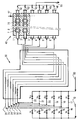
- Hydrocarbon supply lines 11, 12, 13, 14, 15, 16 controlled respectively by valves V1, V2, V3, V4, V5 and V6 introduce into a steam cracker 30 then into a reactor 40 for pyrolysis and decoking of hydrocarbons, for example ethane, from a line 10 mixed with water generally in vapor form provided by a line 60.
- This line distributes it in lines 17, 18, 19, 20, 21 and 22 controlled respectively by valves V7, V8, V9, V10, V11 and V12.
- valves V1 to V12 are adapted to allow the circulation of a mixture of hydrocarbons and water vapor in a certain number of tubes of the steam cracker 30 and of adjacent rows of the so-called pyrolysis reactor 40 and only of water vapor in other steam cracker 30 tubes and other adjacent rows of the so-called decoking reactor 40 for removing the coke which has been deposited during the steam cracking and pyrolysis reaction respectively.
- Steam cracker tubes 31, 32, 33, 34, 35, 36 transporting the mixture of hydrocarbons and water or transporting water alone, connected respectively to lines 11 and 22, 12 and 21, 13 and 20, 14 and 19, 15 and 18 and finally, 16 and 17, are heated in the steam cracker 30 to a temperature of 850 to 900 ° C so as to crack part of the hydrocarbon charge and are connected respectively to rows 1, 2, 3, 4 , 5 and 6 of the pyrolysis reactor 40.
- valve V1 closing the line 11
- the tube 31 receives only the water vapor supplied by line 22 controlled by valve V12.
- the tubes 32, 33, 34, 35 and 36 receive the hydrocarbon and water mixture, all the other valves mentioned being open.
- All the tubes are preheated to around 400 ° C, essentially by convective heating in the first part of the heating oven, then at around 900 ° C in the second part of oven, essentially by radiative heating, by means of a plurality of burners.
- the steam cracking effluent is introduced into the pyrolysis reactor 40 by lines of very short junction, not performing the function of quenching.
- the pyrolysis reactor 40 adjacent to the steam cracking reactor 30 is divided into rows longitudinal (1, 2, 3, 4, 5 and 6) substantially parallel to its axis. These rows are separate from each other by partitions, 70, not leaktight in ceramic material, of shape comprising cells adapted to promote turbulence inside the row and therefore to favor the reaction. These rows contain sheaths of ceramic material 7 forming a sheet substantially parallel to the axis of the reactor. These sheaths are substantially parallel between them and substantially perpendicular to the axis of the reactor. They contain, for example, a plurality of electrical resistors 8 bathed in a sheath gas, chosen in the group formed by water vapor, hydrogen, carbon monoxide, an inert gas and a mixture of two or more of these gases.
- the tube 31 containing water vapor is connected by a shortest heated line possible with row 1 of reactor 40.
- the water vapor flow rate is increased inserted in the tube and in the row where decoking takes place, for example 2 to 3 times that used in the other tubes 32, 33, 34, 35 and the other rows 2, 3, 4, 5 and 6 where the pyrolysis.
- the outlet temperature of the pyrolysis reactor 40 is heated to around 1200 ° C.
- the terminal part of the various rows of reactor 40 intended for pyrolysis or for decoking, receives the pyrolysis or decoking effluents and each row is connected to a direct quenching line 47, comprising a controlled flow injector, for example of ethane if the charge is ethane, which allows these effluents to be cooled.
- a direct quenching line 47 comprising a controlled flow injector, for example of ethane if the charge is ethane, which allows these effluents to be cooled.
- lines 41, 42, 43, 44, 45 and 46 respectively connected to rows 1, 2, 3, 4, 5 and 6 mix the various effluents which are discharged through a line 50.
- the effluents can be cooled by circulating through watertight conduits arranged in the end part of the rows by indirect quenching, then mixed as described above.
- the pyrolysis and decoking effluents from rows 1, 2, 3, 4, 5 and 6 are collected by lines 41, 42, 43, 44, 45 and 46, then mixed and sent in a direct or indirect quenching zone and once cooled evacuated by line 50.
- the heating elements 8 of the pyrolysis reactor are supplied with electrical energy from independently thanks to a pair of electrodes not shown in the figure, probes thermocouple pyrometry not shown are housed in the spaces where the charge and allow to automatically regulate the temperature of each section of heating, by a conventional regulation and modulation device not shown on the figure, depending on the temperature profile chosen which applies equally well to the reaction of pyrolysis than that of decoking the walls of the sheaths.
- a temperature regulation device which may be the same, also makes it possible to control the temperature of the steam cracking reactor burners so that this temperature is lower than the outlet temperature of the oil collected and the final decoking effluent from the pyrolysis reactor.
- a steam cracker-pyrolysis reactor assembly described according to FIG. 1 is used to crack a mixture of ethane and water vapor to produce a mixture of ethylene and acetylene.
- the weight ratio of water vapor to ethane is 1.8.
- the mixture (ethane-water) and the decoking vapor are brought to 900 ° C. in the reactor 30 steam cracking and heated in a substantially linear manner up to 1200 ° C in the pyrolysis reactor at an absolute pressure of 1.3 bar.
- the steam cracker has six heating tubes.
- the pyrolysis reactor has six heating rows substantially parallel to its axis and separated by partitions in the form of cells and ceramic material such as carbide silicon for example. Each row includes a tablecloth parallel to the axis of elements electric heaters.
- the ducts perpendicular to the axis of the reactor, surrounding the electrical resistors are made of silicon carbide and contain a sheath gas which is nitrogen.
- decoking is checked by disappearance of carbon monoxide, which is analyzed online by infrared, for example at the outlet of the pyrolysis oven. It is found that decoking is almost complete after 14 hours in each tube and row where it is carried out and we immediately go back into a steam cracking reaction situation for the tube which has been decoked and pyrolysis for the row which has been decoked.
- An industrial steam cracker effluent is used as the pyrolysis hydrocarbon charge.
- ethane having operated at a temperature of 900 ° C, this effluent being cooled by quenching indirect at 450 ° C.
- This charge, introduced by line 10, is divided between five lines (n ° 11, 13, 14, 15 and 16) corresponding as for the example above to the five working rows in pyrolysis (n ° 1, 3, 4, 5 and 6).
- each row of the pyrolysis zone 258 kg / h of hydrocarbons are introduced and of hydrogen and 86 kg / h of water from the conventional steam cracker and by each line 17, 18, 19, 20 or 22, 378 kg / h of water.
- valve V2 of hydrocarbons In row 2 of the pyrolysis zone operating in decoking, the valve V2 of hydrocarbons being closed, 979 kg / h of water vapor is sent through valve V11 and line 21.
Landscapes
- Chemical & Material Sciences (AREA)
- Oil, Petroleum & Natural Gas (AREA)
- Physics & Mathematics (AREA)
- Thermal Sciences (AREA)
- Engineering & Computer Science (AREA)
- Chemical Kinetics & Catalysis (AREA)
- General Chemical & Material Sciences (AREA)
- Organic Chemistry (AREA)
- Production Of Liquid Hydrocarbon Mixture For Refining Petroleum (AREA)
- Organic Low-Molecular-Weight Compounds And Preparation Thereof (AREA)
- Feeding, Discharge, Calcimining, Fusing, And Gas-Generation Devices (AREA)
Description
L'invention concerne un procédé de pyrolyse d'une charge hydrocarbonée à au moins deux atomes de carbone et simultanément un procédé de décokage du coke déposé sur les parois du réacteur.The invention relates to a process for pyrolysis of a hydrocarbon feedstock with at least two carbon atoms and simultaneously a process for decoking the coke deposited on the walls of the reactor.
Elle s'applique notamment à la production en continu d'acétylène ou de composés acétyléniques comme le méthyl-acétylène.It applies in particular to the continuous production of acetylene or of compounds acetylenics such as methyl acetylene.
Dans les procédés de transformation thermique à haute température d'hydrocarbures ayant au moins un atome de carbone, par exemple une pyrolyse entre 900 et 1 500 °C ou un vapocraquage vers 850 °C en fin de zone de chauffage, du coke se forme et se dépose à la surface des parois du réacteur. On réalise alors un décokage du réacteur qui se fait habituellement avec un mélange air/vapeur à des températures le plus souvent inférieures à 900 °C, en essayant dans le cas de fours métalliques d'éviter toute surchauffe ou points chauds préjudiciables à la bonne tenue des tubes métalliques du four. Ce décokage exothermique implique donc l'arrêt de toute l'unité et surtout la déconnexion du four des échangeurs thermiques en aval, ce qui réduit la productivité totale de l'unité. Par ailleurs, les règles de sécurité imposent le démontage des lignes d'introduction des hydrocarbures et leur remplacement par des lignes d'introduction de l'air, ce qui impose un arrêt très long de l'unité.In high temperature thermal transformation processes of hydrocarbons having minus one carbon atom, for example pyrolysis between 900 and 1500 ° C or a steam cracking around 850 ° C at the end of the heating zone, coke is formed and deposited at the surface of the reactor walls. We then decoke the reactor which is done usually with an air / steam mixture at temperatures most often below 900 ° C, trying in the case of metal ovens to avoid any overheating or points hot damaging the good performance of the metal tubes of the oven. This decoking exothermic therefore involves shutting down the entire unit and above all disconnecting the oven from downstream heat exchangers, which reduces the total productivity of the unit. In addition, safety rules impose the dismantling of the hydrocarbon introduction lines and their replacement by air introduction lines, which requires a very long shutdown of the unit.
Lors du remontage de l'unité pour la phase de pyrolyse, les mêmes inconvénients demeurent auxquels s'ajoute la nécessité de purger la zone réactionnelle et les lignes avec un gaz inerte.When reassembling the unit for the pyrolysis phase, the same drawbacks remain to which is added the need to purge the reaction zone and the lines with an inert gas.
La pyrolyse d'hydrocarbures à au moins deux atomes de carbone permettant d'obtenir des composés hydrocarbonés oléfiniques ou acétyléniques a été décrite, notamment dans les demandes de brevet de la demanderesse FR 2715583 (US-5,554,347), EP-A-733.609 et FR 95/15527 incorporées comme références.Pyrolysis of hydrocarbons with at least two carbon atoms, making it possible to obtain olefinic or acetylenic hydrocarbon compounds has been described, in particular in Applicant's patent applications FR 2715583 (US-5,554,347), EP-A-733,609 and FR 95/15527 incorporated as references.
L'arrière plan technologique est illustré par les brevets EP-A-542.597 et FR 1501836.The technological background is illustrated by patents EP-A-542,597 and FR 1501836.
On a notamment utilisé des réacteurs de pyrolyse en matière céramique dans lesquels des cloisons non étanches avantageusement en matière céramique déterminent des canaux où circulent la charge et les effluents réactionnels. Ces cloisons ont avantageusement une forme adaptée à créer des turbulences et comportent par exemple des alvéoles ou des cavités au niveau des moyens de chauffage. Ceux-ci sont en général des gaines contenant un chauffage électrique ou un brûleur à gaz. In particular, pyrolysis reactors made of ceramic material have been used in which non-watertight partitions advantageously made of ceramic material determine channels where the charge and the reaction effluents circulate. These partitions advantageously have a shape adapted to create turbulence and include, for example, cells or cavities in the level of heating means. These are usually ducts containing a heater electric or a gas burner.
Cependant, ces réacteurs de haute technologie présentent un coût d'investissement élevé et leur alimentation en énergie, notamment électrique induit un coût de fonctionnement important. On a déjà décrit dans le demande de brevet EP-A-733.609 la possibilité d'utiliser un effluent de vapocraquage dont la température est déjà d'environ 850 °C, comme charge du réacteur de pyrolyse puisqu'il contient déjà des hydrocarbures insaturés. L'énergie nécessaire à la conversion de la charge en hydrocarbures acétyléniques en serait alors d'autant plus réduite.However, these high-tech reactors have a high investment cost and their power supply, in particular electrical power, induces a significant operating cost. We have already described in patent application EP-A-733,609 the possibility of using an effluent from steam cracking, the temperature of which is already around 850 ° C, as feedstock to the pyrolysis since it already contains unsaturated hydrocarbons. The energy needed to conversion of the charge into acetylenic hydrocarbons would then be all the more reduced.
Mais un vapocraqueur industriel doit être arrêté tous les deux ou trois mois pour le décoker. Un four de pyrolyse fonctionnant à plus haute température doit être décoké plus souvent, tous les quatre à cinq jours par exemple. Lors de l'étape de décokage, ce four doit être isolé. Il n'existe malheureusement pas de vannes d'étanchéité fonctionnant entre 800 et 900 °C. Une variante consiste alors à envoyer l'effluent du vapocraqueur, refroidi après un passage dans un échangeur de trempe, dans le four de pyrolyse, mais on perd le bénéfice d'utilisation du gaz chaud et le gain devient alors faible. Par ailleurs, le volume mort de l'échangeur de trempe favorise les réactions secondaires au détriment du rendement en éthylène.But an industrial steam cracker must be stopped every two or three months to decoker it. A higher temperature pyrolysis oven should be decoked more often, every four to five days for example. During the decoking stage, this oven must be isolated. There is no unfortunately no sealing valves operating between 800 and 900 ° C. Variant then consists in sending the effluent from the steam cracker, cooled after passing through a quench exchanger in the pyrolysis oven, but the benefit of using the gas is lost warm and the gain becomes low. Furthermore, the dead volume of the quench exchanger promotes side reactions at the expense of ethylene yield.
Un autre inconvénient est lié à la fréquence de décokage des tubes, tous les deux ou trois mois. En effet, en fin de cycle, l'intérieur des tubes est recouvert d'une épaisse couche de coke. Du coke est susceptible de se détacher par moments et est entraíné par le flux gazeux à des vitesses de l'ordre de 200 m/s risquant d'endommager les gaines en matière céramique du four de pyrolyse en aval du four de vapocraquage.Another drawback is related to the frequency of decoking of the tubes, every two or three month. Indeed, at the end of the cycle, the inside of the tubes is covered with a thick layer of coke. Coke may come off at times and is entrained by the gas flow to speeds of the order of 200 m / s risking damage to the ceramic sheaths of the pyrolysis oven downstream of the steam cracking oven.
Un objet de l'invention est de proposer un procédé permettant de pyrolyser une charge hydrocarbonée sans arrêt de l'unité tout en permettant le décokage de cette unité.An object of the invention is to provide a method for pyrolyzing a charge hydrocarbon without stopping the unit while allowing decoking of this unit.
Un autre objet est de réduire les coûts d'investissement et de fonctionnement de l'unité.Another object is to reduce the investment and operating costs of the unit.
Un autre objet de l'invention est de maintenir la température de l'installation sensiblement constante durant sa marche, pour éviter les contraintes thermiques qui ne manqueraient pas de se produire, notamment lors de l'utilisation d'un gaz contenant de l'oxygène pour l'étape de décokage qui met en oeuvre une réaction exothermique alors que l'étape de pyrolyse met en oeuvre une réaction endothermique.Another object of the invention is to maintain the temperature of the installation substantially constant during its walk, to avoid thermal stresses which would not fail to occur, especially when using an oxygen-containing gas for the stage of decoking which implements an exothermic reaction while the pyrolysis step puts in performs an endothermic reaction.
Compte tenu de la présence des cloisons non étanches donc bon marché dans la zone de pyrolyse, on a remarqué qu'il était possible de mettre en oeuvre en continu un procédé de pyrolyse d'une charge hydrocarbonée et un procédé de décokage de la zone réactionnelle qui ne soient pas pénalisants.Given the presence of non-watertight bulkheads therefore inexpensive in the area of pyrolysis, we noticed that it was possible to continuously implement a process of pyrolysis of a hydrocarbon feedstock and a process for decoking the reaction zone which are not penalizing.
On a remarqué qu'en combinant un four de vapocraquage travaillant avec un taux élevé de dilution de la charge par de la vapeur d'eau et au moins un four de pyrolyse à très haute température, en l'absence d'un échangeur de trempe entre le four de vapocraquage et le four de pyrolyse, on observait une excellente sélectivité en produits désirés, pour une demande enthalpique globale réduite.It has been noticed that by combining a steam cracking furnace working with a high rate of dilution of the charge by steam and at least one very high pyrolysis oven temperature, in the absence of a quenching exchanger between the steam cracking furnace and the furnace of pyrolysis, an excellent selectivity was observed in desired products, for a demand reduced overall enthalpy.
De manière plus précise, l'invention concerne un procédé de pyrolyse et de décokage en continu dans une zone de réaction comprenant une zone de pyrolyse (40) en matière réfractaire, de forme allongée selon une direction (un axe) comportant une zone de chauffage et une zone de refroidissement faisant suite à la zone de chauffage, la zone de chauffage comprenant au moins deux rangées (1, 2) sensiblement parallèles à l'axe, séparées par une cloison (70), avantageusement non étanche, en matériau réfractaire entre deux rangées successives, au moins l'une desdites rangées (1) recevant des hydrocarbures et de la vapeur d'eau, au moins une autre (2) desdites rangées recevant essentiellement de la vapeur d'eau, lesdites rangées comportant des moyens de chauffage (8) entourés de gaines (7) sensiblement parallèles entre elles et sensiblement perpendiculaires à l'axe du réacteur, du coke se déposant dans la zone de réaction, le procédé étant caractérisé en ce qu'on fait circuler une charge hydrocarbonée contenant au moins un hydrocarbure à au moins deux atomes de carbone à une température adéquate de vapocraquage dans une zone de vapocraquage contenant au moins deux tubes de vapocraquage, au moins un desdits tubes communiquant avec une alimentation en la charge et en vapeur d'eau et étant chauffé de façon à craquer la charge, au moins un autre desdits tubes communiquant avec une alimentation en un fluide consistant essentiellement en vapeur d'eau et étant chauffé de façon à décoker ledit tube sur lequel s'est déposé du coke, le débit de vapeur d'eau dans le tube de vapocraquage étant tel que le rapport pondéral vapeur d'eau/charge est compris entre 0,5 et 20, on obtient un courant gazeux de vapocraquage comprenant les hydrocarbures et la vapeur d'eau et un courant gazeux de décokage comprenant essentiellement de la vapeur d'eau et on fait circuler le courant de vapocraquage dans au moins une rangée de la zone de chauffage de la zone de pyrolyse (40) qui est adjacente à la zone de vapocraquage de façon à pyrolyser le courant de vapocraquage et à avoir une température de sortie de ladite zone de chauffage d'au moins 850 °C et on fait circuler le courant de décokage dans au moins l'autre rangée de la zone de chauffage de façon à décoker au moins en partie ladite rangée et à avoir une température de sortie de ladite zone de chauffage d'au moins 850 °C et l'on recueille des hydrocarbures comprenant au moins un composé acétylénique par exemple l'acétylène et un effluent de décokage.More specifically, the invention relates to a pyrolysis and decoking process in continuous in a reaction zone comprising a pyrolysis zone (40) made of material refractory, elongated in a direction (an axis) having a heating zone and a cooling zone following the heating zone, the heating zone comprising at least two rows (1, 2) substantially parallel to the axis, separated by a partition (70), advantageously not watertight, of refractory material between two rows successive, at least one of said rows (1) receiving hydrocarbons and steam of water, at least one other (2) of said rows essentially receiving water vapor, said rows comprising heating means (8) surrounded by sheaths (7) substantially parallel to each other and substantially perpendicular to the axis of the reactor, coke depositing in the reaction zone, the process being characterized in that a charge is circulated hydrocarbon containing at least one hydrocarbon with at least two carbon atoms to an adequate steam cracking temperature in a steam cracking zone containing at least at least two steam cracking tubes, at least one of said tubes communicating with a feeding the load and steam and being heated so as to crack the load, at at least one other of said tubes communicating with a supply of a fluid consisting essentially in steam and being heated so as to decoker said tube on which is deposited coke, the water vapor flow rate in the steam cracking tube being such that the ratio by weight water vapor / charge is between 0.5 and 20, a gas stream of steam cracking comprising hydrocarbons and water vapor and a gas stream of decoking essentially comprising water vapor and circulating the current of steam cracking in at least one row of the heating zone of the pyrolysis zone (40) which is adjacent to the steam cracking area so as to pyrolyze the steam cracking stream and to have an outlet temperature of said heating zone of at least 850 ° C. and we do circulate the decoking current in at least the other row of the heating zone so at least partially decoking said row and having an exit temperature from said zone heating at least 850 ° C and collecting hydrocarbons comprising at least one acetylene compound for example acetylene and a decoking effluent.
Selon une caractéristique de l'invention, la température de sortie de la zone de vapocraquage est en règle générale, inférieure à la température de sortie de la zone de chauffage de la zone de pyrolyse.According to a characteristic of the invention, the exit temperature from the steam cracking zone is generally lower than the outlet temperature of the zone heating zone pyrolysis.
La température dans le ou les tubes de vapocraquage où s'effectue le vapocraquage de la charge est avantageusement maintenue sensiblement égale à la température dans le ou les tubes où s'effectue le décokage. De même, la température dans la ou les rangées où s'effectue la pyrolyse du courant gazeux sortant de la zone de vapocraquage est avantageusement maintenue sensiblement égale à la température dans la ou les rangées où s'effectue le décokage.The temperature in the steam cracking tube (s) where the steam cracking takes place the charge is advantageously maintained substantially equal to the temperature in the tubes where decoking takes place. Likewise, the temperature in the row or rows where the pyrolysis of the gas stream leaving the steam cracking zone is advantageously maintained approximately equal to the temperature in the row or rows where the decoking.
Selon une autre caractéristique particulièrement avantageuse, la température de sortie de la zone de chauffage relative aux hydrocarbures et la température de sortie de la zone de chauffage relative à l'effluent de décokage sont d'environ 1 000 à 1 400 °C.According to another particularly advantageous characteristic, the outlet temperature of the heating zone relative to hydrocarbons and the exit temperature from the heating relative to the decoking effluent are about 1000 to 1400 ° C.
Selon une autre caractéristique, la quantité de vapeur d'eau introduite dans la zone de vapocraquage, par rapport à celle de la charge, en d'autres termes le rapport pondéral vapeur d'eau sur charge, pour une charge déterminée est supérieur à celui correspondant à un vapocraquage conventionnel de la même charge. On adopte généralement celui qui est le plus approprié à la réaction de pyrolyse faisant suite à la réaction de vapocraquage.According to another characteristic, the amount of water vapor introduced into the zone of steam cracking, compared to that of the charge, in other words the steam weight ratio of water on charge, for a determined charge is greater than that corresponding to a conventional steam cracking of the same charge. We generally adopt the one that is the most suitable for the pyrolysis reaction following the steam cracking reaction.
Ainsi, pour une charge consistant essentiellement en éthane, ce rapport est supérieur à 0,5 alors qu'il est d'environ 0,2 habituellement. Pour une charge de naphta, le rapport est supérieur à 0,7 alors qu'il est habituellement d'environ 0,5. A titre d'exemple, également pour une charge de gazole, le rapport est supérieur à 1, par exemple égal à 2 alors qu'il est habituellement voisin de 1.Thus, for a charge consisting essentially of ethane, this ratio is greater than 0.5 while it is usually around 0.2. For a charge of naphtha, the ratio is higher at 0.7 while it is usually around 0.5. For example, also for a charge of diesel, the ratio is greater than 1, for example equal to 2 whereas it is usually close to 1.
On a obtenu d'excellents résultats en termes de sélectivité avec un rapport vapeur d'eau sur charge compris entre 1,5 et 6, la valeur la plus élevée étant de préférence adaptée aux charges les plus lourdes.Excellent results have been obtained in terms of selectivity with a water vapor to load between 1.5 and 6, the highest value preferably being adapted to the loads the heaviest.
Le choix de ces rapports combiné à une température de réaction élevée, aussi bien pour la zone de vapocraquage que pour la zone de chauffage de la zone de pyrolyse facilite le décokage des tubes et des rangées puisque ce sont des conditions suffisamment oxydantes à ces températures pour transformer le coke et pour former de l'oxyde de carbone et de l'hydrogène.The choice of these ratios combined with a high reaction temperature, both for the steam cracking zone only for the heating zone of the pyrolysis zone facilitates the decoking of tubes and rows since these are sufficiently oxidizing conditions to these temperatures to transform coke and to form carbon monoxide and hydrogen.
Ceci est particulièrement avantageux dans le cas du réacteur de pyrolyse en matière céramique comportant des cloisons non étanches. Un transfert de vapeur d'eau et d'hydrogène peut donc s'effectuer à travers la paroi de la rangée où s'effectue le décokage vers la rangée où s'effectue la pyrolyse.This is particularly advantageous in the case of the material pyrolysis reactor. ceramic with bulkheads. Water vapor and hydrogen transfer can therefore be carried out through the wall of the row where decoking is carried out towards the row where pyrolysis takes place.
Il a même été observé qu'un transfert d'hydrogène vers la rangée de pyrolyse ralentissait le dépôt de coke sur celle-ci.It has even been observed that a transfer of hydrogen to the pyrolysis row slowed down the deposit of coke on it.
Par ailleurs, un transfert de vapeur d'eau de la rangée où s'effectue le décokage vers la rangée où s'effectue la pyrolyse n'est pas pénalisant puisque la réaction de pyrolyse s'effectue en présence de vapeur d'eau. Dans l'autre sens, si des hydrocarbures passent de la rangée de pyrolyse vers la rangée où s'effectue le décokage, ils vont se trouver en présence d'une quantité importante d'eau et seront pyrolysés en produits recherchés sans faire du coke supplémentaire.In addition, a transfer of water vapor from the row where decoking takes place to the row where the pyrolysis takes place is not penalizing since the pyrolysis reaction takes place in presence of water vapor. In the other direction, if hydrocarbons pass from the row of pyrolysis towards the row where decoking takes place, they will be in the presence of a significant amount of water and will be pyrolyzed into desired products without making coke additional.
Enfin, le choix d'un rapport élevé en vapeur d'eau sur charge présente l'avantage de diminuer le dépôt de coke. Celui-ci ne pourra d'ailleurs pas croítre de manière importante puisqu'il est prévu de décoker tous les quatre ou cinq jours par exemple, c'est-à-dire à une fréquence correspondant à celle du décokage du réacteur de pyrolyse, au lieu de décoker tous les deux à trois mois dans le cas des vapocraqueurs industriels.Finally, the choice of a high water vapor to charge ratio has the advantage of reducing the coke deposit. It will not be able to grow significantly since it is planned to decoker every four or five days for example, that is to say at a frequency corresponding to that of decoking the pyrolysis reactor, instead of decoking both at three months in the case of industrial steam crackers.
Cette diminution du dépôt de coke, du fait de la forte teneur en vapeur d'eau et de la fréquence de décokage, favorise le transfert thermique à travers les tubes (le dépôt de coke crée une barrière thermique), on a donc des températures de peau de tubes inférieures à celles des vapocraqueurs industriels, ce qui amène un gain de sélectivité en éthylène par rapport à ces derniers.This decrease in coke deposition, due to the high water vapor content and the frequency decoking, promotes heat transfer through the tubes (the deposit of coke creates a thermal barrier), so we have lower tube skin temperatures than industrial steam crackers, which leads to a gain in selectivity for ethylene compared to these last.
D'autre part, le vapocraqueur étant relié au four de pyrolyse par une conduite très courte, il n'y a pratiquement pas de volume mort alors que, lorsqu'on utilise l'effluent d'un vapocraqueur industriel comme charge du réacteur de pyrolyse, le fait de devoir refroidir le gaz dans un échangeur thermique crée un volume mort important où se forment des produits secondaires indésirables, par dégradation à haute température de l'éthylène et de l'acétylène. On the other hand, the steam cracker being connected to the pyrolysis furnace by a very short pipe, there is has practically no dead volume whereas when using the effluent from a steam cracker industrial as a pyrolysis reactor charge, having to cool the gas in a heat exchanger creates a large dead volume where secondary products are formed undesirable, by high temperature degradation of ethylene and acetylene.
On a par ailleurs constaté qu'en adoptant un débit de vapeur d'eau dans le tube où s'effectue le décokage 1,1 à 4 fois supérieur au débit de vapeur d'eau introduite dans le tube où s'effectue le vapocraquage, on obtenait de très bons résultats de décokage de ces tubes. Bien entendu, le taux de décokage des rangées de chauffage adjacentes aux tubes décokés est aussi amélioré puisque cet excès de vapeur circule aussi dans les rangées où s'effectue le décokage.It has also been found that by adopting a water vapor flow rate in the tube where the decoking 1.1 to 4 times greater than the water vapor flow rate introduced into the tube where the steam cracking, very good decoking results were obtained from these tubes. Of course, the decoking rate of heating rows adjacent to decoking tubes is also improved since this excess steam also circulates in the rows where decoking takes place.
Pour réaliser cette étape de décokage, on coupe l'alimentation en hydrocarbures dans le tube destiné à être décoké et on augmente sensiblement le débit d'eau introduit de manière à ne pas provoquer de perturbation thermique trop forte dans le four de préchauffe des gaz en amont de la zone de vapocraquage.To carry out this decoking step, the hydrocarbon supply in the tube is cut intended to be decoked and the flow of water introduced is substantially increased so as not to not cause excessive thermal disturbance in the gas preheating furnace upstream of the steam cracking zone.
Le four de vapocraquage est habituellement chauffé par des brûleurs à gaz conventionnels, de type brûleurs radiants. La charge est en général préchauffée entre 300 et 400 °C. La température de la zone de vapocraquage est d'habitude au plus égale à 900 °C.The steam cracking furnace is usually heated by conventional gas burners, type radiant burners. The load is generally preheated between 300 and 400 ° C. The the temperature of the steam cracking zone is usually at most equal to 900 ° C.
Les moyens de chauffage du réacteur de pyrolyse peuvent être des résistances électriques contenues dans des gaines telles que décrites dans les brevets ci-devant ou ils peuvent être constitués de gaines contenant un brûleur à gaz tel que décrit dans la demande de brevet de la demanderesse (FR 2715583).The heating means of the pyrolysis reactor can be electrical resistances contained in sheaths as described in the above patents or they may be consisting of sheaths containing a gas burner as described in the patent application of the Applicant (FR 2715583).
Chaque rangée peut comprendre au moins une nappe de moyens de chauffage entourés de gaines, sensiblement parallèle à l'axe de la zone de réaction, ces gaines étant sensiblement perpendiculaires audit axe.Each row may include at least one layer of heating means surrounded by sheaths, substantially parallel to the axis of the reaction zone, these sheaths being substantially perpendicular to said axis.
Les caractéristiques des éléments chauffants, soit électriques, soit comportant des brûleurs à gaz, leur nombre, la distance les séparant et leur configuration sont décrits dans les brevets cités ci-devant.The characteristics of the heating elements, either electric or comprising burners with gases, their number, the distance between them and their configuration are described in the patents cited above.
Il en est de même pour les gaines les protégeant et les isolant des fluides qui circulent dans le réacteur.It is the same for the sheaths protecting and isolating them from the fluids which circulate in the reactor.
Ces mêmes éléments chauffants et ces mêmes gaines avec les mêmes caractéristiques et les mêmes configurations se retrouvent aussi bien dans la zone de pyrolyse que dans la zone (ou rangée) où s'effectue le décokage à la vapeur d'eau. These same heating elements and these same ducts with the same characteristics and same configurations are found both in the pyrolysis zone and in the zone (or row) where steam decoking takes place.
Par ailleurs, il a été observé, qu'en présence d'éléments chauffants électriques contenus dans des gaines en matière céramique relativement poreuses et peu chères dont l'étanchéité n'est pas parfaite, un gaz de gaine contenant de l'hydrogène et/ou de la vapeur d'eau et/ou du monoxyde de carbone et/ou un gaz inerte pouvait être utilisé et de plus pouvait diffuser de l'intérieur vers l'extérieur des gaines sans perturber la réaction de pyrolyse et sans perturber la réaction de décokage.Furthermore, it has been observed that in the presence of electric heating elements contained in relatively porous and inexpensive ceramic sheaths whose sealing is not not perfect, a cladding gas containing hydrogen and / or water vapor and / or carbon monoxide and / or an inert gas could be used and could also diffuse inside to outside of the sheaths without disturbing the pyrolysis reaction and without disturbing the decoking reaction.
Selon une première variante, les hydrocarbures recueillis et l'effluent de décokage peuvent être mélangés avant d'être introduits dans la zone de refroidissement.According to a first variant, the hydrocarbons collected and the decoking effluent can be mixed before being introduced into the cooling zone.
Selon une deuxième variante, les hydrocarbures recueillis et l'effluent de décokage sont refroidis séparément dans leurs rangées respectives, situées au niveau de la zone de refroidissement, puis éventuellement mélangés.According to a second variant, the hydrocarbons collected and the decoking effluent are cooled separately in their respective rows, located at the level of the cooling, then possibly mixed.
La zone de refroidissement est habituellement une zone de trempe directe par un fluide de refroidissement, connu de l'Homme de métier, suivie avantageusement d'un échangeur à contact indirect générant de la vapeur (TLE : transfer line exchanger).The cooling zone is usually a zone of direct quenching by a cooling, known to those skilled in the art, advantageously followed by a heat exchanger indirect contact generating steam (TLE: transfer line exchanger).
L'installation présente l'avantage d'être sûre, fiable et facile à mettre en oeuvre. Elle utilise dans la zone de pyrolyse, des matériaux réfractaires et plus particulièrement des matières céramiques connues de l'Homme de métier comme la cordiérite, la mullite, le nitrure de silicium ou le carbure de silicium.The installation has the advantage of being safe, reliable and easy to implement. She uses in the pyrolysis zone, refractory materials and more particularly materials ceramics known to those skilled in the art such as cordierite, mullite, silicon nitride or silicon carbide.
Les charges hydrocarbonées utilisables sont à titre d'exemples non limitatifs :
- les hydrocarbures aliphatiques saturés tels que l'éthane et des mélanges d'alcanes (LPG), des coupes pétrolières telles que les naphtas, les gazoles atmosphériques et les gazoles sous vide, ces derniers pouvant présenter un point final de distillation de l'ordre de 570 °C.
- les hydrocarbures insaturés tels que l'éthylène, le propylène et le butadiène, des mélanges d'alcanes et d'alcènes tels que éthane + éthylène, les coupes C3, C4 et C5 de craquage catalytique.
- saturated aliphatic hydrocarbons such as ethane and mixtures of alkanes (LPG), petroleum fractions such as naphthas, atmospheric gas oils and vacuum gas oils, the latter possibly having an end point of distillation of the order of 570 ° C.
- unsaturated hydrocarbons such as ethylene, propylene and butadiene, mixtures of alkanes and alkenes such as ethane + ethylene, cuts C3, C4 and C5 of catalytic cracking.
L'invention concerne aussi une unité de pyrolyse et de décokage en continu pour la mise en oeuvre notamment du procédé selon l'invention, comportant un réacteur (40) de pyrolyse de forme allongée selon une direction (un axe) comprenant au moins deux rangées (1, 2) sensiblement parallèles à l'axe séparées par une cloison, (70) avantageusement non étanche, en matériau réfractaire entre deux rangées successives, chaque rangée comprenant une pluralité de moyens de chauffage (8) disposés en au moins une nappe d'éléments chauffants entourés de gaines (7) en matériau céramique sensiblement parallèles entre elles et sensiblement perpendiculaires à l'axe du réacteur, au moins l'une des rangées (1) étant adaptée à recevoir des hydrocarbures et de la vapeur d'eau, au moins une autre (2) desdites rangées étant adaptée à recevoir de la vapeur d'eau, ledit réacteur de pyrolyse comportant des moyens d'asservissement et de modulation de chauffage reliés aux moyens de chauffage, le réacteur de pyrolyse comprenant en outre des moyens de refroidissement (47) des effluents produits dans chaque rangée, ladite unité étant caractérisée en ce qu'elle comprend un réacteur (30) de vapocraquage comprenant au moins deux tubes (31, 32) de vapocraquage, chacun des tubes (31, 32) étant connecté à une extrémité à une ligne d'alimentation en une charge (11, 12) comportant une vanne de régulation (V1, V2) et à une ligne d'alimentation (22, 21) en vapeur d'eau comportant une vanne de régulation (V12, V11), l'autre extrémité du tube (31) étant reliée à la rangée (1) recevant les hydrocarbures et la vapeur d'eau et l'autre extrémité du tube (32) étant reliée à la rangée (2) recevant la vapeur d'eau, le réacteur de vapocraquage comprenant en outre des moyens pour actionner alternativement lesdites vannes de façon qu'un tube (31) soit en phase de vapocraquage et que l'autre tube (32) soit en phase de décokage, et des moyens de régulation de chauffage de façon que la température du réacteur de vapocraquage soit inférieure à celle du réacteur de pyrolyse.The invention also relates to a continuous pyrolysis and decoking unit for setting up work in particular of the process according to the invention, comprising a reactor (40) for pyrolysis of elongated shape in a direction (an axis) comprising at least two rows (1, 2) substantially parallel to the axis separated by a partition, (70) advantageously not sealed, of refractory material between two successive rows, each row comprising a plurality of heating means (8) arranged in at least one layer of heating elements surrounded by sheaths (7) of ceramic material substantially parallel to each other and substantially perpendicular to the axis of the reactor, at least one of the rows (1) being adapted to receive hydrocarbons and water vapor, at least one other (2) of said rows being adapted to receive water vapor, said pyrolysis reactor comprising heating control and modulation means connected to the heating means, the pyrolysis reactor further comprising means (47) for cooling the effluents products in each row, said unit being characterized in that it comprises a steam cracking reactor (30) comprising at least two steam cracking tubes (31, 32), each of the tubes (31, 32) being connected at one end to a supply line at a load (11, 12) comprising a control valve (V1, V2) and a supply line (22, 21) in steam comprising a regulating valve (V12, V11), the other end of the tube (31) being connected to the row (1) receiving the hydrocarbons and the water vapor and the other end of the tube (32) being connected to the row (2) receiving the steam, the reactor steam cracking further comprising means for alternately actuating said valves so that one tube (31) is in the steam cracking phase and the other tube (32) is in decoking phase, and heating regulation means so that the temperature of the steam cracking reactor is lower than that of the pyrolysis reactor.
L'invention sera mieux comprise par la description d'un mode de réalisation, donnée à titre purement illustratif mais nullement limitatif, qui en sera faite ci-après à l'aide de la figure annexée, qui représente en coupe transversale un vapocraqueur suivi d'une coupe longitudinale, suivant un plan parallèle à l'axe du réacteur (vue de dessus) d'un réacteur de pyrolyse.The invention will be better understood by the description of an embodiment, given as purely illustrative but in no way limiting, which will be made of it below with the aid of the figure attached, which represents in cross section a steam cracker followed by a section longitudinal, along a plane parallel to the axis of the reactor (top view) of a reactor pyrolysis.
Des lignes d'alimentation en hydrocarbures 11, 12, 13, 14, 15, 16 contrôlées respectivement
par des vannes V1, V2, V3, V4, V5 et V6 introduisent dans un vapocraqueur 30 puis dans un
réacteur 40 de pyrolyse et de décokage des hydrocarbures, de l'éthane par exemple, provenant
d'une ligne 10 en mélange avec de l'eau généralement sous forme vapeur apportée par une
ligne 60. Cette ligne la distribue dans des lignes 17, 18, 19, 20, 21 et 22 contrôlées
respectivement par des vannes V7, V8, V9, V10, V11 et V12.
Ces diverses vannes V1 à V12 sont adaptées à permettre la circulation d'un mélange
hydrocarbures et vapeur d'eau dans un certain nombre de tubes du vapocraqueur 30 et de
rangées adjacentes du réacteur 40 dites de pyrolyse et seulement de la vapeur d'eau dans
d'autres tubes du vapocraqueur 30 et d'autres rangées adjacentes du réacteur 40 dites de
décokage pour y enlever le coke qui s'est déposé lors de la réaction respectivement de
vapocraquage et de pyrolyse.
Des tubes du vapocraqueur 31, 32, 33, 34, 35, 36 transportant le mélange des hydrocarbures
et de l'eau ou transportant l'eau seule, connectés respectivement aux lignes 11 et 22, 12 et 21,
13 et 20, 14 et 19, 15 et 18 et enfin, 16 et 17, sont chauffés dans le vapocraqueur 30 à une
température de 850 à 900 °C de manière à craquer une partie de la charge hydrocarbonée et
sont connectés respectivement aux rangées 1, 2, 3, 4, 5 et 6 du réacteur de pyrolyse 40.These various valves V1 to V12 are adapted to allow the circulation of a mixture of hydrocarbons and water vapor in a certain number of tubes of the
Par exemple, la vanne V1 fermant la ligne 11, il en résulte que le tube 31 ne reçoit que de la
vapeur d'eau amenée par la ligne 22 contrôlée par la vanne V12. En revanche, les tubes 32,
33, 34, 35 et 36 reçoivent le mélange hydrocarbures et eau, toutes les autres vannes
mentionnées étant ouvertes.For example, the valve V1 closing the
L'ensemble des tubes est préchauffé à environ 400 °C, essentiellement par chauffage convectif dans la première partie du four de chauffage, puis à environ 900 °C dans la deuxième partie de four, essentiellement par chauffage radiatif, au moyen d'une pluralité de brûleurs.All the tubes are preheated to around 400 ° C, essentially by convective heating in the first part of the heating oven, then at around 900 ° C in the second part of oven, essentially by radiative heating, by means of a plurality of burners.
L'effluent de vapocraquage est introduit dans le réacteur de pyrolyse 40 par des lignes de
jonction très courtes, ne réalisant pas la fonction d'une trempe.The steam cracking effluent is introduced into the
Le réacteur 40 de pyrolyse adjacent au réacteur de vapocraquage 30 est divisé en rangées
longitudinales (1, 2, 3, 4, 5 et 6) sensiblement parallèles à son axe. Ces rangées sont séparées
les unes des autres par des cloisons, 70, non étanches en matière céramique, de forme
comportant des alvéoles adaptées à favoriser des turbulences à l'intérieur de la rangée et donc
à favoriser la réaction. Ces rangées contiennent des gaines en matière céramique 7 formant
une nappe sensiblement parallèle à l'axe du réacteur. Ces gaines sont sensiblement parallèles
entre elles et sensiblement perpendiculaires à l'axe du réacteur. Elles contiennent, par
exemple, une pluralité des résistances électriques 8 baignant dans un gaz de gaine, choisi
dans le groupe formé par la vapeur d'eau, l'hydrogène, le monoxyde de carbone, un gaz inerte
et un mélange de deux ou plusieurs de ces gaz.The
Le tube 31 contenant de la vapeur d'eau est connecté par une ligne chauffée la plus courte
possible avec la rangée 1 du réacteur 40. Généralement, on augmente le débit de vapeur d'eau
introduite dans le tube et dans la rangée où s'effectue le décokage, par exemple 2 à 3 fois celui
utilisé dans les autres tubes 32, 33, 34, 35 et les autres rangées 2, 3, 4, 5 et 6 où s'effectue la
pyrolyse. La température de sortie du réacteur 40 de pyrolyse est chauffé d'environ 1200 °CThe
La partie terminale des diverses rangées du réacteur 40, destinée à la pyrolyse ou au
décokage, reçoit les effluents de pyrolyse ou de décokage et chaque rangée est connectée à
une ligne 47 de trempe directe, comprenant un injecteur à débit contrôlé, par exemple d'éthane
si la charge est de l'éthane, ce qui permet de refroidir ces effluents. Une fois refroidis vers 800
°C par exemple, des lignes 41, 42, 43, 44, 45 et 46 connectées respectivement aux rangées 1,
2, 3, 4, 5 et 6 mélangent les divers effluents qui sont évacués par une ligne 50.The terminal part of the various rows of
Selon un autre mode non illustré, les effluents peuvent être refroidis en circulant à travers des conduits étanches disposés dans la partie terminale des rangées par trempe indirecte, puis mélangés comme décrit ci-dessus.According to another mode not illustrated, the effluents can be cooled by circulating through watertight conduits arranged in the end part of the rows by indirect quenching, then mixed as described above.
Selon un autre mode non illustré, les effluents de pyrolyse et de décokage issus des rangées 1,
2, 3, 4, 5 et 6 sont collectés par les lignes 41, 42, 43, 44, 45 et 46, puis mélangés et envoyés
dans une zone de trempe directe ou indirecte et une fois refroidis évacués par la ligne 50.According to another mode, not illustrated, the pyrolysis and decoking effluents from
Les éléments de chauffage 8 du réacteur de pyrolyse sont alimentés en énergie électrique de
façon indépendante grâce à une paire d'électrodes non représentées sur la figure, des sondes
pyrométriques à thermocouple non représentées sont logées dans les espaces où circule la
charge et permettent de réguler automatiquement la température de chaque section de
chauffage, par un dispositif classique de régulation et de modulation non représenté sur la
figure, en fonction du profil de température choisi qui s'applique aussi bien à la réaction de
pyrolyse qu'à celle de décokage des parois des gaines.The
Un dispositif de régulation de température, qui peut être le même, permet, par ailleurs, de contrôler la température des brûleurs du réacteur de vapocraquage de façon que cette température soit inférieure à la température de sortie des hydrocarbures recueillis et de l'effluent final de décokage du réacteur de pyrolyse.A temperature regulation device, which may be the same, also makes it possible to control the temperature of the steam cracking reactor burners so that this temperature is lower than the outlet temperature of the oil collected and the final decoking effluent from the pyrolysis reactor.
On utilise un ensemble vapocraqueur-réacteur de pyrolyse décrit selon la figure 1 pour craquer un mélange d'éthane et de vapeur d'eau en vue de produire un mélange d'éthylène et d'acétylène. Le rapport pondéral vapeur d'eau sur éthane est de 1,8. A steam cracker-pyrolysis reactor assembly described according to FIG. 1 is used to crack a mixture of ethane and water vapor to produce a mixture of ethylene and acetylene. The weight ratio of water vapor to ethane is 1.8.
Le mélange (éthane-eau) et la vapeur de décokage sont portés à 900 °C dans le réacteur 30
de vapocraquage et chauffés de manière sensiblement linéaire jusqu'à 1 200 °C dans le
réacteur de pyrolyse sous une pression absolue de 1,3 bar.The mixture (ethane-water) and the decoking vapor are brought to 900 ° C. in the
Le vapocraqueur comporte six tubes de chauffage.The steam cracker has six heating tubes.
Le réacteur de pyrolyse comporte six rangées de chauffage sensiblement parallèles à son axe et séparées par des cloisons en forme d'alvéoles et en matière céramique tel que le carbure de silicium par exemple. Chaque rangée comprend une nappe parallèle à l'axe d'éléments chauffants électriques. Les gaines perpendiculaires à l'axe du réacteur, entourant les résistances électriques sont en carbure de silicium et contiennent un gaz de gaine qui est de l'azote.The pyrolysis reactor has six heating rows substantially parallel to its axis and separated by partitions in the form of cells and ceramic material such as carbide silicon for example. Each row includes a tablecloth parallel to the axis of elements electric heaters. The ducts perpendicular to the axis of the reactor, surrounding the electrical resistors are made of silicon carbide and contain a sheath gas which is nitrogen.
Cinq tubes de chauffage du vapocraqueur (n° 31, 33, 34, 35 et 36) ainsi que cinq rangées du réacteur de pyrolyse (n° 1, 3, 4, 5 et 6) travaillent en pyrolyse tandis qu'un seul tube de chauffage (n° 32) et qu'une seule rangée (n° 2) travaillent en décokage.Five steam cracker heating tubes (nos. 31, 33, 34, 35 and 36) as well as five rows of pyrolysis reactor (n ° 1, 3, 4, 5 and 6) work in pyrolysis while a single tube heating (n ° 32) and only one row (n ° 2) is working on decoking.
Dans chaque tube de vapocraquage, on introduit 258 kg/h d'éthane et 464 kg/h de vapeur d'eau, tandis que dans le tube opérant en décokage, on introduit 979 kg/h de vapeur d'eau par la vanne V11, la vanne V2 d'hydrocarbures étant fermée.258 kg / h of ethane and 464 kg / h of steam are introduced into each steam cracking tube of water, while in the tube operating in decoking, 979 kg / h of steam are introduced by the valve V11, the valve V2 of hydrocarbons being closed.
L'effluent de vapocraquage contenant des hydrocarbures, de l'hydrogène et de la vapeur d'eau est introduit directement dans les rangées appropriées du réacteur de pyrolyse. L'effluent de décokage du tube est introduit directement dans la rangée du réacteur de pyrolyse soumise au décokage. En sortie de réacteur de pyrolyse, l'effluent de pyrolyse est refroidi à 800 °C par contact direct avec 91 kg/h d'éthane à 16 °C tandis que l'effluent de décokage est refroidi à 800 °C par contact direct avec 85 kg/h d'éthane à 16 °C.Steam cracking effluent containing hydrocarbons, hydrogen and water vapor is introduced directly into the appropriate rows of the pyrolysis reactor. The effluent from tube decoking is introduced directly into the row of the pyrolysis reactor subjected to decoking. At the outlet of the pyrolysis reactor, the pyrolysis effluent is cooled to 800 ° C. by direct contact with 91 kg / h of ethane at 16 ° C while the decoking effluent is cooled to 800 ° C by direct contact with 85 kg / h of ethane at 16 ° C.
Après 72 heures de pyrolyse dans la rangée n° 1, on décide de procéder au décokage de celle-ci.
Pour cela, on coupe le débit d'éthane par la vanne V1 et pour éviter une perturbation du
régime thermique du vapocraqueur et du four de pyrolyse, on augmente le débit de vapeur
d'eau (vanne V12) jusqu'à obtenir 979 kg/h. Simultanément, on alimente à nouveau le tube 32
et la rangée n° 2 avec 258 kg/h d'éthane et 464 kg/h de vapeur d'eau, en ouvrant la vanne V2
et la vanne V11. After 72 hours of pyrolysis in row n ° 1, it is decided to decoke it.
For this, the ethane flow is cut by the valve V1 and to avoid a disturbance of the
thermal regime of the steam cracker and the pyrolysis oven, the steam flow is increased
of water (valve V12) until 979 kg / h is obtained. Simultaneously, the
On contrôle la fin du décokage par disparition du monoxyde de carbone, lequel est analysé en
ligne par infrarouge par exemple en sortie de four de pyrolyse.
On constate que le décokage est quasiment complet au bout de 14 heures dans chaque tube
et rangée où il est réalisé et on repasse aussitôt en situation de réaction de vapocraquage pour
le tube qui a été décoké et de pyrolyse pour la rangée qui a été décokée.The end of decoking is checked by disappearance of carbon monoxide, which is analyzed online by infrared, for example at the outlet of the pyrolysis oven.
It is found that decoking is almost complete after 14 hours in each tube and row where it is carried out and we immediately go back into a steam cracking reaction situation for the tube which has been decoked and pyrolysis for the row which has been decoked.
On a donc cinq tubes en vapocraquage reliés à cinq rangées en pyrolyse et un tube dans le
réacteur de vapocraquage connecté à une rangée dans le réacteur de pyrolyse en décokage.
On produit ainsi de manière constante et sans arrêt prolongé de l'unité 536 kg/h d'éthylène et
450 kg/h d'acétylène. Les effluents des six rangées du réacteur 40 sont mélangés et envoyés
par la ligne 50 vers les traitements et les séparations des produits.We therefore have five steam cracking tubes connected to five rows in pyrolysis and one tube in the
steam cracking reactor connected to a row in the decoking pyrolysis reactor.
536 kg / h of ethylene are produced constantly and without prolonged shutdown of the unit.
450 kg / h of acetylene. The effluents from the six rows of
Bien évidemment, compte tenu de la durée de décokage adaptée à la charge choisie, on aurait pu disposer d'un réacteur comportant dix rangées de pyrolyse et deux rangées de décokage soit voisines, soit séparées et reliées à un four de vapocraquage comportant douze tubes au total dont deux seraient simultanément décokés.Obviously, taking into account the decoking time adapted to the chosen load, we would have could have a reactor with ten rows of pyrolysis and two rows of decoking either adjacent or separated and connected to a steam cracking furnace comprising twelve tubes at total of which two would be simultaneously decoked.
On utilise comme charge hydrocarbonée de pyrolyse un effluent de vapocraqueur industriel
d'éthane, ayant opéré à une température de 900 °C, cet effluent étant refroidi par une trempe
indirecte à 450 °C. Cette charge, introduite par la ligne 10, est répartie entre cinq lignes (n° 11,
13, 14, 15 et 16) correspondant comme pour l'exemple ci-dessus aux cinq rangées travaillant
en pyrolyse (n° 1, 3, 4, 5 et 6).An industrial steam cracker effluent is used as the pyrolysis hydrocarbon charge.
ethane, having operated at a temperature of 900 ° C, this effluent being cooled by quenching
indirect at 450 ° C. This charge, introduced by
Dans chaque rangée de la zone de pyrolyse, on introduit 258 kg/h d'hydrocarbures et
d'hydrogène et 86 kg/h d'eau provenant du vapocraqueur conventionnel et par chaque ligne 17,
18, 19, 20 ou 22, 378 kg/h d'eau.In each row of the pyrolysis zone, 258 kg / h of hydrocarbons are introduced and
of hydrogen and 86 kg / h of water from the conventional steam cracker and by each
Dans la rangée n° 2 de la zone de pyrolyse opérant en décokage, la vanne V2 d'hydrocarbures
étant fermée, on envoie 979 kg/h de vapeur d'eau par la vanne V11 et la ligne 21.In row 2 of the pyrolysis zone operating in decoking, the valve V2 of hydrocarbons
being closed, 979 kg / h of water vapor is sent through valve V11 and
Bien entendu, dans cette version le réacteur 30 n'existe plus et les lignes 11 à 16 sont
connectées directement respectivement aux rangées 1 à 6.Of course, in this version the
On utilise les mêmes cycles que pour l'exemple précédent. On produit 510 kg/h d'éthylène et 440 kg/h d'acétylène.The same cycles are used as for the previous example. 510 kg / h of ethylene are produced and 440 kg / h of acetylene.
Claims (13)
- A continuous pyrolysis and decoking process carried out in a reaction zone comprising a pyrolysis zone (40) which is of refractory material, which is elongate in one direction (one axis), and which comprises a heating zone and a cooling zone following the heating zone, the heating zone comprising at least two rows (1, 2) which are substantially parallel to the axis separated by a wall (70) of refractory material and located between two successive rows, at least one of said rows (1) receiving hydrocarbons and steam, at least one other (2) of said rows receiving essentially steam, said rows comprising heating means (8) surrounded by sleeves (7) which are substantially parallel to each other and substantially perpendicular to the reactor axis, wherein coke is deposited in the reaction zone, the process being characterized in that a hydrocarbon feed comprising at least one hydrocarbon containing at least two carbon atoms is circulated at a temperature which is sufficient for steam cracking in a steam cracking zone containing at least two steam cracking tubes, at least one of said tubes communicating with a supply for feed and steam and being heated so as to crack the feed, at least one other of said tubes communicating with a supply for a fluid consisting essentially of steam and being heated so as to decoke said tube on which coke has been deposited, the flow rate of steam in the steam cracking tube being such that the steam/feed weight ratio is in the range 0 5 to 20, a steam cracking gas stream comprising hydrocarbons and steam and a decoking gas stream comprising essentially steam are obtained and the steam cracking stream is circulated in at least one row of the heating zone in the pyrolysis zone (40) which is adjacent the steam cracking zone so as to pyrolyse the steam cracking stream and to produce a temperature of at least 850°C at the outlet from said heating zone, and the decoking stream is circulated in at least the other row of the heating zone so as to decoke said row at least in part, and to produce a temperature of at least 850°C at the outlet from said heating zone, and in which hydrocarbons comprising at least one acetylenic compound are recovered along with a decoking effluent.
- A process according to claim 1, in which the temperature at the outlet from the steam cracking zone is lower than the temperature at the outlet from the heating zone in the pyrolysis zone.
- A process according to claim 1 or claim 2, in which the steam-to-feed ratio for a given feed is higher than the steam-to-feed ratio for conventional steam cracking of said feed
- A process according to any one of claims 1 to 3, in which the steam-to-feed ratio is more than 0 5 for a feed which consists essentially of ethane.
- A process according to any one of claims I to 3, in which the steam-to-feed ratio is more than 0.7 for a feed consisting essentially of naphtha
- A process according to any one of claims 1 to 3, in which the steam-to-feed ratio is more than 1 for a feed consisting essentially of a gas oil
- A process according to any one of claims 1 to 6, in which the steam flow rate in the tube in which decoking is carried out is 1.1 to 4 times higher than the steam flow rate introduced into the tube in which steam cracking is carried out.
- A process according to any one of claims 1 to 7, in which the recovered hydrocarbons and the decoking effluent are mixed before being introduced into the cooling zone.
- A process according to any one of claims 1 to 7, in which the recovered hydrocarbons and the decoking effluent are cooled separately in their respective rows in the cooling zone then are optionally mixed.
- A process according to any one of claims 1 to 9, in which the recovered hydrocarbons and the decoking effluent are directly cooled.
- A process according to any one of claims 1 to 10, in which the temperature at the outlet from the heating zone for the hydrocarbons and the temperature at the outlet from the heating zone for the decoking effluent are about 1000°C to 1400°C.
- A process according to any one of claims 1 to 11, in which the temperature in the steam cracking zone is at most 900°C.
- A pyrolysis and decoking unit for carrying out the process according to any one of claims 1 to 12, comprising a pyrolysis reactor (40) which is elongate in one direction (one axis) comprising at least two rows (1, 2) which are substantially parallel to the axis separated by a wall (70) of refractory material located between two successive rows, each row comprising a plurality of heating means (8) disposed in at least one layer of heating elements surrounded by sleeves (7) of ceramic material which are substantially parallel to each other and substantially perpendicular to the reactor axis, at least one of the rows (1) being adapted to receive hydrocarbons and steam, at least one other (2) of said rows being adapted to receive steam, said pyrolysis reactor comprising means for heat control and modulation connected to the heating means, the pyrolysis reactor further comprising cooling means (47) for the effluents produced in each row, said unit being characterized in that it comprises a steam cracking reactor (30) comprising at least two steam cracking tubes (31, 32), each of said tubes (31, 32) being connected to an extremity of a supply line for a feed (11, 12) comprising a regulating valve (V1, V2) and a supply line (22, 21) for steam comprising a regulating valve (V12, V11), the other extremity of tube (31) being connected to the row (1) receiving hydrocarbons and steam and the other extremity of tube (32) being connected to the row (2) receiving steam, the steam cracking reactor further comprising means for alternately activating said valves such that one tube (31) is in the steam cracking phase and the other tube (32) is in the decoking phase, and heat regulation means such that the temperature of the steam cracking reactor is lower than that of the pyrolysis reactor.
Applications Claiming Priority (2)
| Application Number | Priority Date | Filing Date | Title |
|---|---|---|---|
| FR9605760 | 1996-05-06 | ||
| FR9605760A FR2748273B1 (en) | 1996-05-06 | 1996-05-06 | METHOD AND DEVICE FOR THE THERMAL CONVERSION OF HYDROCARBONS INTO ALIPHATIC HYDROCARBONS MORE UNSATURATED THAN THE STARTING PRODUCTS, COMBINING A STAGE OF STEAM CRACKING AND A STAGE OF PYROLYSIS |
Publications (2)
| Publication Number | Publication Date |
|---|---|
| EP0806467A1 EP0806467A1 (en) | 1997-11-12 |
| EP0806467B1 true EP0806467B1 (en) | 2000-12-27 |
Family
ID=9491959
Family Applications (1)
| Application Number | Title | Priority Date | Filing Date |
|---|---|---|---|
| EP97400998A Expired - Lifetime EP0806467B1 (en) | 1996-05-06 | 1997-05-02 | Process and apparatus for the thermal conversion of hydrocarbons into more insaturated aliphatic hydrocarbons by combination of a steam cracking and a pyrolysis step |
Country Status (11)
| Country | Link |
|---|---|
| US (2) | US5976352A (en) |
| EP (1) | EP0806467B1 (en) |
| JP (1) | JP4251303B2 (en) |
| AU (1) | AU726569B2 (en) |
| CA (1) | CA2204541C (en) |
| DE (1) | DE69703763T2 (en) |
| ES (1) | ES2154448T3 (en) |
| FR (1) | FR2748273B1 (en) |
| ID (1) | ID17841A (en) |
| MY (1) | MY113653A (en) |
| NO (1) | NO314507B1 (en) |
Families Citing this family (23)
| Publication number | Priority date | Publication date | Assignee | Title |
|---|---|---|---|---|
| FR2791665B1 (en) * | 1999-03-31 | 2001-05-18 | Inst Francais Du Petrole | PROCESS FOR PRODUCING METHYLACETYLENE AND PROPADIENE |
| FR2796078B1 (en) | 1999-07-07 | 2002-06-14 | Bp Chemicals Snc | PROCESS AND DEVICE FOR VAPOCRACKING HYDROCARBONS |
| US6585883B1 (en) | 1999-11-12 | 2003-07-01 | Exxonmobil Research And Engineering Company | Mitigation and gasification of coke deposits |
| US7846401B2 (en) | 2005-12-23 | 2010-12-07 | Exxonmobil Research And Engineering Company | Controlled combustion for regenerative reactors |
| US7513260B2 (en) * | 2006-05-10 | 2009-04-07 | United Technologies Corporation | In-situ continuous coke deposit removal by catalytic steam gasification |
| US7914667B2 (en) * | 2007-06-04 | 2011-03-29 | Exxonmobil Chemical Patents Inc. | Pyrolysis reactor conversion of hydrocarbon feedstocks into higher value hydrocarbons |
| US20090022635A1 (en) * | 2007-07-20 | 2009-01-22 | Selas Fluid Processing Corporation | High-performance cracker |
| US8083932B2 (en) * | 2007-08-23 | 2011-12-27 | Shell Oil Company | Process for producing lower olefins from hydrocarbon feedstock utilizing partial vaporization and separately controlled sets of pyrolysis coils |
| US8278231B2 (en) * | 2008-11-24 | 2012-10-02 | Exxonmobil Chemical Patents Inc. | Heat stable formed ceramic, apparatus and method of using the same |
| US8748686B2 (en) * | 2008-11-25 | 2014-06-10 | Exxonmobil Chemical Patents Inc. | Conversion of co-fed methane and low hydrogen content hydrocarbon feedstocks to acetylene |
| US8815080B2 (en) * | 2009-01-26 | 2014-08-26 | Lummus Technology Inc. | Adiabatic reactor to produce olefins |
| US8512663B2 (en) | 2009-05-18 | 2013-08-20 | Exxonmobile Chemical Patents Inc. | Pyrolysis reactor materials and methods |
| US8399372B2 (en) * | 2009-05-18 | 2013-03-19 | Exxonmobil Chemical Patents Inc. | Stabilized ceramic composition, apparatus and methods of using the same |
| US8450552B2 (en) * | 2009-05-18 | 2013-05-28 | Exxonmobil Chemical Patents Inc. | Pyrolysis reactor materials and methods |
| JP5363932B2 (en) * | 2009-09-28 | 2013-12-11 | 株式会社日立製作所 | Chemical equipment |
| US8932534B2 (en) | 2009-11-20 | 2015-01-13 | Exxonmobil Chemical Patents Inc. | Porous pyrolysis reactor materials and methods |
| US8784515B2 (en) | 2010-10-14 | 2014-07-22 | Precision Combustion, Inc. | In-situ coke removal |
| MX370102B (en) * | 2013-10-22 | 2019-12-02 | Bechtel Hydrocarbon Technology Solutions Inc | On-line pigging and spalling coker furnace outlets. |
| US10870803B2 (en) * | 2016-07-16 | 2020-12-22 | Ramin Karimzadeh | Method for upgrading a hydrocarbon feed |
| US20190292466A1 (en) * | 2018-03-26 | 2019-09-26 | Dennis Carl England | Control, method for pyrolysis process of low-rank-coal |
| CN112538365B (en) * | 2019-09-23 | 2022-11-01 | 中国石化工程建设有限公司 | Coke cleaning system for cracking gas pipeline of ethylene cracking furnace and coke preventing and removing method for cracking gas pipeline |
| EP4237514A4 (en) * | 2020-11-02 | 2024-12-11 | Lummus Technology LLC | ELECTRIC FURNACE FOR THE PRODUCTION OF OLEFINS |
| FR3150266B1 (en) * | 2023-06-23 | 2025-06-27 | Totalenergies Onetech | OVEN EQUIPPED WITH HYBRID RADIANT HEATING SYSTEMS FOR HEATING OR TREATING A LOAD AND METHOD OF HEATING OR TREATING SUCH A LOAD USING THE OVEN |
Family Cites Families (17)
| Publication number | Priority date | Publication date | Assignee | Title |
|---|---|---|---|---|
| US1470359A (en) * | 1917-04-17 | 1923-10-09 | Gasolene Corp | Process of removing carbon from metal pipes |
| US3365387A (en) * | 1966-04-29 | 1968-01-23 | Exxon Research Engineering Co | Off-stream decoking of a minor portion of on-stream thermal cracking tubes |
| US3641190A (en) * | 1969-01-22 | 1972-02-08 | Exxon Research Engineering Co | Decoking of onstream thermal cracking tubes |
| EP0021167B1 (en) * | 1979-06-08 | 1982-03-03 | Linde Aktiengesellschaft | Process and apparatus for the thermal decoking of an apparatus for the thermal cracking of hydrocarbons such apparatus comprising a cracking zone followed by a cooler for the product gas |
| US4329150A (en) * | 1980-12-11 | 1982-05-11 | Mobil Oil Corporation | Method and apparatus for control and optimization of pyrolysis furnace with multiple parallel passes |
| EP0074435B1 (en) * | 1981-09-08 | 1986-01-02 | Dow Chemical (Nederland) B.V. | Process and apparatus for cracking hydrocarbon; mixing device; apparatus and process for producing superheated steam; radiation block structure |
| US4492624A (en) * | 1982-09-30 | 1985-01-08 | Stone & Webster Engineering Corp. | Duocracking process for the production of olefins from both heavy and light hydrocarbons |
| US4552644A (en) * | 1982-09-30 | 1985-11-12 | Stone & Webster Engineering Corporation | Duocracking process for the production of olefins from both heavy and light hydrocarbons |
| ES2067741T3 (en) * | 1989-04-14 | 1995-04-01 | Procedes Petroliers Petrochim | PROCEDURE AND INSTALLATION FOR THE DESCOQUIFICADO OF A VAPOCRAQUEO INSTALLATION. |
| FR2648145B1 (en) * | 1989-06-08 | 1991-10-04 | Inst Francais Du Petrole | USE OF NICKEL-BASED ALLOYS IN A PROCESS OF THERMAL CRACKING OF AN OIL LOAD AND REACTOR FOR IMPLEMENTING THE PROCESS |
| FR2683543B1 (en) * | 1991-11-08 | 1994-02-11 | Inst Francais Du Petrole | PROCESS FOR THERMAL PYROLYSIS OF HYDROCARBONS USING AN ELECTRIC OVEN. |
| KR940009317A (en) * | 1992-10-05 | 1994-05-20 | 알버트 어네스트 가레드 | Coke removal method using air pulse |
| FR2715583B1 (en) * | 1994-02-02 | 1996-04-05 | Inst Francais Du Petrole | Device for carrying out chemical reactions requiring at least starting calories. |
| FR2728580A1 (en) * | 1994-12-26 | 1996-06-28 | Inst Francais Du Petrole | PROCESS AND INSTALLATION OF SPRAYING COMPRISING THE INJECTION OF POWDERS COLLECTED AT A SINGLE POINT |
| FR2732014B1 (en) * | 1995-03-23 | 1997-05-23 | Inst Francais Du Petrole | PROCESS FOR THE THERMAL CONVERSION OF SATURATED OR UNSATURATED ALIPHATIC HYDROCARBONS TO ACETYLENIC HYDROCARBONS |
| FR2743007B1 (en) * | 1995-12-27 | 1998-01-30 | Inst Francais Du Petrole | CONTINUOUS PYROLYSIS AND DECOKING PROCESS APPLICABLE IN PARTICULAR TO THE PRODUCTION OF ACETYLENE |
| US5829747A (en) | 1997-09-02 | 1998-11-03 | Nebel; Stephen E. | Stock market big board game |
-
1996
- 1996-05-06 FR FR9605760A patent/FR2748273B1/en not_active Expired - Fee Related
-
1997
- 1997-05-02 DE DE69703763T patent/DE69703763T2/en not_active Expired - Lifetime
- 1997-05-02 ES ES97400998T patent/ES2154448T3/en not_active Expired - Lifetime
- 1997-05-02 EP EP97400998A patent/EP0806467B1/en not_active Expired - Lifetime
- 1997-05-02 MY MYPI97001933A patent/MY113653A/en unknown
- 1997-05-05 ID IDP971496A patent/ID17841A/en unknown
- 1997-05-05 CA CA002204541A patent/CA2204541C/en not_active Expired - Fee Related
- 1997-05-05 NO NO19972070A patent/NO314507B1/en not_active IP Right Cessation
- 1997-05-05 AU AU20029/97A patent/AU726569B2/en not_active Ceased
- 1997-05-06 JP JP11589697A patent/JP4251303B2/en not_active Expired - Fee Related
- 1997-05-06 US US08/851,998 patent/US5976352A/en not_active Expired - Lifetime
-
1999
- 1999-09-03 US US09/389,224 patent/US6322760B1/en not_active Expired - Fee Related
Also Published As
| Publication number | Publication date |
|---|---|
| FR2748273B1 (en) | 1998-06-26 |
| CA2204541A1 (en) | 1997-11-06 |
| DE69703763D1 (en) | 2001-02-01 |
| NO972070L (en) | 1997-11-07 |
| AU726569B2 (en) | 2000-11-09 |
| JP4251303B2 (en) | 2009-04-08 |
| MY113653A (en) | 2002-04-30 |
| US5976352A (en) | 1999-11-02 |
| JPH10279507A (en) | 1998-10-20 |
| US6322760B1 (en) | 2001-11-27 |
| EP0806467A1 (en) | 1997-11-12 |
| DE69703763T2 (en) | 2001-04-19 |
| AU2002997A (en) | 1997-11-13 |
| CA2204541C (en) | 2008-07-15 |
| ES2154448T3 (en) | 2001-04-01 |
| ID17841A (en) | 1998-01-29 |
| FR2748273A1 (en) | 1997-11-07 |
| NO314507B1 (en) | 2003-03-31 |
| NO972070D0 (en) | 1997-05-05 |
Similar Documents
| Publication | Publication Date | Title |
|---|---|---|
| EP0806467B1 (en) | Process and apparatus for the thermal conversion of hydrocarbons into more insaturated aliphatic hydrocarbons by combination of a steam cracking and a pyrolysis step | |
| EP0229093B1 (en) | Process for the vapocracking of hydrocarbons | |
| EP0226487B1 (en) | Process for the thermal conversion of methane into hydrocarbons with a higher molecular weight | |
| EP0781828B1 (en) | Continuous pyrolysis and decoking process, particularly applicable to the production of acetylene | |
| EP0542597B1 (en) | Thermal hydrocarbon pyrolysis process using an electric furnace | |
| EP0666104B1 (en) | Apparatus for carrying out chemical reactions which, at least during start-up, require a supply of calories | |
| FR2710070A1 (en) | Method and device for steam cracking a light load and a heavy load. | |
| WO1990015119A1 (en) | Use of nickel-based alloys in thermal cracking of a petroleum charge and a reactor for the implementation of said process | |
| EP0252356A1 (en) | Process and furnace for the steam cracking of hydrocarbons for the preparation of olefins and diolefins | |
| EP0252355B1 (en) | Process and furnace for the steam cracking of hydrocarbons for the preparation of olefins and diolefins | |
| EP0539270B1 (en) | Process for the thermal conversion of methane and reactor for this process | |
| FR2641543A1 (en) | METHOD AND DEVICE FOR VAPOCRAQUING A HYDROCARBON WITH TWO ATOMS OF CARBON AT LEAST IN A CONVECTION-HEATED TUBULAR REACTION ZONE | |
| EP0289391B1 (en) | Process for the thermal conversion of methane into hydrocarbons with a higher molecular weight, reactors to be used in this process and process for the realization of the reactors | |
| EP0733609B1 (en) | Process for the thermal conversion of aliphatically saturated or unsaturated hydrocarbons in acetylenic hydrocarbons | |
| EP0323287B1 (en) | Process for the thermal conversion of methane into hydrocarbons with a higher molecular weight, and reactor to be used in this process | |
| EP1041060B1 (en) | Process for the preparation of methylacetylene and propadiene | |
| FR2589859A1 (en) | Process for the thermal conversion of methane to higher molecular weight hydrocarbons | |
| FR2703141A1 (en) | Device for carrying out endothermic reactions and its applications | |
| FR2600641A1 (en) | Process and furnace for steam cracking of gaseous hydrocarbons intended for the manufacture of olefins and diolefins | |
| FR2600642A1 (en) | Process and furnace for steam cracking of gaseous hydrocarbons for the manufacture of olefins and diolefins | |
| FR2648471A1 (en) | Multichannel reactor made of ceramic material comprising means for creating turbulence in the fluid in contact therewith | |
| FR2653779A1 (en) | Process for decoking a plant for steam-cracking hydrocarbons and corresponding plant |
Legal Events
| Date | Code | Title | Description |
|---|---|---|---|
| PUAI | Public reference made under article 153(3) epc to a published international application that has entered the european phase |
Free format text: ORIGINAL CODE: 0009012 |
|
| AK | Designated contracting states |
Kind code of ref document: A1 Designated state(s): BE DE ES GB IT NL SE |
|
| 17P | Request for examination filed |
Effective date: 19980512 |
|
| GRAG | Despatch of communication of intention to grant |
Free format text: ORIGINAL CODE: EPIDOS AGRA |
|
| 17Q | First examination report despatched |
Effective date: 20000229 |
|
| GRAG | Despatch of communication of intention to grant |
Free format text: ORIGINAL CODE: EPIDOS AGRA |
|
| GRAH | Despatch of communication of intention to grant a patent |
Free format text: ORIGINAL CODE: EPIDOS IGRA |
|
| GRAH | Despatch of communication of intention to grant a patent |
Free format text: ORIGINAL CODE: EPIDOS IGRA |
|
| ITF | It: translation for a ep patent filed | ||
| GRAA | (expected) grant |
Free format text: ORIGINAL CODE: 0009210 |
|
| AK | Designated contracting states |
Kind code of ref document: B1 Designated state(s): BE DE ES GB IT NL SE |
|
| REF | Corresponds to: |
Ref document number: 69703763 Country of ref document: DE Date of ref document: 20010201 |
|
| GBT | Gb: translation of ep patent filed (gb section 77(6)(a)/1977) |
Effective date: 20010115 |
|
| REG | Reference to a national code |
Ref country code: ES Ref legal event code: FG2A Ref document number: 2154448 Country of ref document: ES Kind code of ref document: T3 |
|
| PLBE | No opposition filed within time limit |
Free format text: ORIGINAL CODE: 0009261 |
|
| STAA | Information on the status of an ep patent application or granted ep patent |
Free format text: STATUS: NO OPPOSITION FILED WITHIN TIME LIMIT |
|
| 26N | No opposition filed | ||
| REG | Reference to a national code |
Ref country code: GB Ref legal event code: IF02 |
|
| PGFP | Annual fee paid to national office [announced via postgrant information from national office to epo] |
Ref country code: SE Payment date: 20040526 Year of fee payment: 8 |
|
| PG25 | Lapsed in a contracting state [announced via postgrant information from national office to epo] |
Ref country code: SE Free format text: LAPSE BECAUSE OF NON-PAYMENT OF DUE FEES Effective date: 20050503 |
|
| EUG | Se: european patent has lapsed | ||
| REG | Reference to a national code |
Ref country code: DE Ref legal event code: R081 Ref document number: 69703763 Country of ref document: DE Owner name: IFP ENERGIES NOUVELLES, FR Free format text: FORMER OWNERS: GAZ DE FRANCE, PARIS, FR; INSTITUT FRANCAIS DU PETROLE, RUEIL-MALMAISON, HAUTS-DE-SEINE, FR Effective date: 20110329 Ref country code: DE Ref legal event code: R081 Ref document number: 69703763 Country of ref document: DE Owner name: GAZ DE FRANCE, FR Free format text: FORMER OWNERS: GAZ DE FRANCE, PARIS, FR; INSTITUT FRANCAIS DU PETROLE, RUEIL-MALMAISON, HAUTS-DE-SEINE, FR Effective date: 20110329 Ref country code: DE Ref legal event code: R081 Ref document number: 69703763 Country of ref document: DE Owner name: IFP ENERGIES NOUVELLES, FR Free format text: FORMER OWNER: GAZ DE FRANCE, INSTITUT FRANCAIS DU PETROLE, , FR Effective date: 20110329 Ref country code: DE Ref legal event code: R081 Ref document number: 69703763 Country of ref document: DE Owner name: GAZ DE FRANCE, FR Free format text: FORMER OWNER: GAZ DE FRANCE, INSTITUT FRANCAIS DU PETROLE, , FR Effective date: 20110329 |
|
| PGFP | Annual fee paid to national office [announced via postgrant information from national office to epo] |
Ref country code: ES Payment date: 20110512 Year of fee payment: 15 |
|
| PGFP | Annual fee paid to national office [announced via postgrant information from national office to epo] |
Ref country code: NL Payment date: 20110531 Year of fee payment: 15 Ref country code: BE Payment date: 20110531 Year of fee payment: 15 Ref country code: GB Payment date: 20110525 Year of fee payment: 15 |
|
| PGFP | Annual fee paid to national office [announced via postgrant information from national office to epo] |
Ref country code: DE Payment date: 20110601 Year of fee payment: 15 Ref country code: IT Payment date: 20110519 Year of fee payment: 15 |
|
| BERE | Be: lapsed |
Owner name: *GAZ DE FRANCE Effective date: 20120531 Owner name: INSTITUT FRANCAIS DU *PETROLE Effective date: 20120531 |
|
| REG | Reference to a national code |
Ref country code: NL Ref legal event code: V1 Effective date: 20121201 |
|
| GBPC | Gb: european patent ceased through non-payment of renewal fee |
Effective date: 20120502 |
|
| PG25 | Lapsed in a contracting state [announced via postgrant information from national office to epo] |
Ref country code: BE Free format text: LAPSE BECAUSE OF NON-PAYMENT OF DUE FEES Effective date: 20120531 Ref country code: IT Free format text: LAPSE BECAUSE OF NON-PAYMENT OF DUE FEES Effective date: 20120502 |
|
| REG | Reference to a national code |
Ref country code: DE Ref legal event code: R119 Ref document number: 69703763 Country of ref document: DE Effective date: 20121201 |
|
| PG25 | Lapsed in a contracting state [announced via postgrant information from national office to epo] |
Ref country code: NL Free format text: LAPSE BECAUSE OF NON-PAYMENT OF DUE FEES Effective date: 20121201 |
|
| PG25 | Lapsed in a contracting state [announced via postgrant information from national office to epo] |
Ref country code: GB Free format text: LAPSE BECAUSE OF NON-PAYMENT OF DUE FEES Effective date: 20120502 |
|
| PG25 | Lapsed in a contracting state [announced via postgrant information from national office to epo] |
Ref country code: DE Free format text: LAPSE BECAUSE OF NON-PAYMENT OF DUE FEES Effective date: 20121201 |
|
| REG | Reference to a national code |
Ref country code: ES Ref legal event code: FD2A Effective date: 20130821 |
|
| PG25 | Lapsed in a contracting state [announced via postgrant information from national office to epo] |
Ref country code: ES Free format text: LAPSE BECAUSE OF NON-PAYMENT OF DUE FEES Effective date: 20120503 |