EP0806313B1 - Vehicle convertible - Google Patents
Vehicle convertible Download PDFInfo
- Publication number
- EP0806313B1 EP0806313B1 EP97105887A EP97105887A EP0806313B1 EP 0806313 B1 EP0806313 B1 EP 0806313B1 EP 97105887 A EP97105887 A EP 97105887A EP 97105887 A EP97105887 A EP 97105887A EP 0806313 B1 EP0806313 B1 EP 0806313B1
- Authority
- EP
- European Patent Office
- Prior art keywords
- vehicle according
- convertible vehicle
- roof
- hollow profiled
- parts
- Prior art date
- Legal status (The legal status is an assumption and is not a legal conclusion. Google has not performed a legal analysis and makes no representation as to the accuracy of the status listed.)
- Expired - Lifetime
Links
- 239000000463 material Substances 0.000 claims description 6
- 229910052782 aluminium Inorganic materials 0.000 claims description 2
- XAGFODPZIPBFFR-UHFFFAOYSA-N aluminium Chemical compound [Al] XAGFODPZIPBFFR-UHFFFAOYSA-N 0.000 claims description 2
- 230000013011 mating Effects 0.000 claims 6
- 239000004411 aluminium Substances 0.000 claims 1
- 238000009434 installation Methods 0.000 description 7
- 238000007789 sealing Methods 0.000 description 4
- 239000000853 adhesive Substances 0.000 description 3
- 230000001070 adhesive effect Effects 0.000 description 3
- 230000008859 change Effects 0.000 description 3
- 238000013461 design Methods 0.000 description 3
- 238000011161 development Methods 0.000 description 2
- 230000018109 developmental process Effects 0.000 description 2
- 239000004744 fabric Substances 0.000 description 2
- 238000003466 welding Methods 0.000 description 2
- 238000005253 cladding Methods 0.000 description 1
- 238000005352 clarification Methods 0.000 description 1
- 238000010276 construction Methods 0.000 description 1
- 238000009749 continuous casting Methods 0.000 description 1
- 230000006378 damage Effects 0.000 description 1
- 230000000694 effects Effects 0.000 description 1
- 238000001125 extrusion Methods 0.000 description 1
- 230000010354 integration Effects 0.000 description 1
- 230000007774 longterm Effects 0.000 description 1
- 238000004519 manufacturing process Methods 0.000 description 1
- 239000012528 membrane Substances 0.000 description 1
- 229910052751 metal Inorganic materials 0.000 description 1
- 239000002184 metal Substances 0.000 description 1
- 238000000034 method Methods 0.000 description 1
- 230000008569 process Effects 0.000 description 1
- 238000012545 processing Methods 0.000 description 1
- 230000009467 reduction Effects 0.000 description 1
- 230000002040 relaxant effect Effects 0.000 description 1
- 239000003351 stiffener Substances 0.000 description 1
- 239000004753 textile Substances 0.000 description 1
- 238000012549 training Methods 0.000 description 1
- 230000000007 visual effect Effects 0.000 description 1
Images


Classifications
-
- B—PERFORMING OPERATIONS; TRANSPORTING
- B60—VEHICLES IN GENERAL
- B60J—WINDOWS, WINDSCREENS, NON-FIXED ROOFS, DOORS, OR SIMILAR DEVICES FOR VEHICLES; REMOVABLE EXTERNAL PROTECTIVE COVERINGS SPECIALLY ADAPTED FOR VEHICLES
- B60J7/00—Non-fixed roofs; Roofs with movable panels, e.g. rotary sunroofs
- B60J7/08—Non-fixed roofs; Roofs with movable panels, e.g. rotary sunroofs of non-sliding type, i.e. movable or removable roofs or panels, e.g. let-down tops or roofs capable of being easily detached or of assuming a collapsed or inoperative position
- B60J7/12—Non-fixed roofs; Roofs with movable panels, e.g. rotary sunroofs of non-sliding type, i.e. movable or removable roofs or panels, e.g. let-down tops or roofs capable of being easily detached or of assuming a collapsed or inoperative position foldable; Tensioning mechanisms therefor, e.g. struts
- B60J7/1226—Soft tops for convertible vehicles
- B60J7/1234—Soft tops for convertible vehicles characterised by arches, e.g. shape or material
-
- B—PERFORMING OPERATIONS; TRANSPORTING
- B60—VEHICLES IN GENERAL
- B60J—WINDOWS, WINDSCREENS, NON-FIXED ROOFS, DOORS, OR SIMILAR DEVICES FOR VEHICLES; REMOVABLE EXTERNAL PROTECTIVE COVERINGS SPECIALLY ADAPTED FOR VEHICLES
- B60J10/00—Sealing arrangements
- B60J10/90—Sealing arrangements specially adapted for non-fixed roofs, e.g. foldable roofs or removable hard-tops
-
- B—PERFORMING OPERATIONS; TRANSPORTING
- B60—VEHICLES IN GENERAL
- B60J—WINDOWS, WINDSCREENS, NON-FIXED ROOFS, DOORS, OR SIMILAR DEVICES FOR VEHICLES; REMOVABLE EXTERNAL PROTECTIVE COVERINGS SPECIALLY ADAPTED FOR VEHICLES
- B60J7/00—Non-fixed roofs; Roofs with movable panels, e.g. rotary sunroofs
- B60J7/08—Non-fixed roofs; Roofs with movable panels, e.g. rotary sunroofs of non-sliding type, i.e. movable or removable roofs or panels, e.g. let-down tops or roofs capable of being easily detached or of assuming a collapsed or inoperative position
- B60J7/12—Non-fixed roofs; Roofs with movable panels, e.g. rotary sunroofs of non-sliding type, i.e. movable or removable roofs or panels, e.g. let-down tops or roofs capable of being easily detached or of assuming a collapsed or inoperative position foldable; Tensioning mechanisms therefor, e.g. struts
- B60J7/1226—Soft tops for convertible vehicles
- B60J7/123—Soft tops for convertible vehicles characterised by means for fastening the soft top cloth to the arches or vehicle body work
Definitions
- the invention relates to a convertible vehicle with a Folding hood carrying convertible top frame according to the preamble of claim 1.
- Convertible top frame assembly from a variety of screwed Individual parts formed in one piece as extruded metal parts with a groove profile are provided, to accommodate additional retaining strips is provided.
- the assembly of these items with a Convertible top roof skin is in a variety of connection pairs, especially screw and nail connections, extremely complex.
- the invention has for its object a convertible vehicle that mentioned in the preamble of claim 1 Art to create, the convertible top frame with individual components is provided, which is a total at reduced weight simplified assembly and sufficiently stable mounting of the Folding roof roof skin in the area of the respective connecting parts allow such that the roof in the closed position in Area of the roof bow a uniform roof contour offers.
- the convertible top frame designed according to the invention has in Area of the extruded profile parts each have a cross-sectional geometry on that with a low material consumption directed cavity structure with improved Overall stability, a reduction in weight of the convertible top frame guaranteed, while at the same time the extruded profile parts with respective admission profiles and / or undercuts are provided in cross section, so that for corresponding counterparts of assigned Components and / or connecting parts of the roof skin extremely easy to assemble connection areas created are.
- extruded profiles can be manufactured at low cost with little effort to different support and Holding conditions, especially in the area of connection pairings when installing the roof skin.
- the roof bow are in the Wall contour of the one having a hollow profile cross section Extruded profile part with several receiving chambers slit-shaped receiving openings provided over the each with the convertible top roof skin and / or the inner Headliner connected to the headlining in the receiving chamber are insertable that the clamping piping in this position sufficient via a positive connection intervention are firmly attached to the roof bow and the Roof skin overall over a contour shape in the closed position the given support can be clamped.
- the clamping strip is guided in the receiving slot so that a largely free mobility when relaxing the roof membrane is reached and thus changes in the load the clamping piping or the roof skin, especially for frequent ones Repetitions of opening and closing movements of the Convertible top frame, balanced by a movement of the clamping piping become.
- the clamping piping can be in the area the roof bow is extremely easy to assemble and disassemble become.
- connection profile part On its underside facing the vehicle interior the hollow profile part also with a connection profile provided on the one connected to the headliner Counter member or a clamping keder is releasably fixable, so that this connection area as a whole is extremely simple mountable and for disassembly, for example at a change in the roof skin and / or the headlining, suitable is.
- the hollow profile part for example in its component height, for different Roof skin structures can be designed variably, so that the hollow profile part without direct contact or connection surfaces in a free space on the top cover can be integrated between the upholstered mat and the headlining is.
- the Roof skin In the closed position of the convertible top frame, the Roof skin a uniformly flat contour without in the area of Roof bows visible elevations or waveforms, so that the overall visual impression of the Cabriolet vehicle is improved overall.
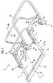
- Fig. 1 is a convertible top frame, generally designated 1 a convertible vehicle, not shown illustrates, with the clarification of the essential Individual parts of this structure a this spanning roof skin 2 only in the cutouts 2 to 7 is visible.
- the convertible top linkage 1 is symmetrical to the longitudinal axis of the vehicle 3 arranged as well as front and rear Provide sections 4, 5 existing side frame parts 6, 7, the one ends over a main column 8 and a main guide rod 9 pivotable on a rear Main bearing 10 of the vehicle body 11 supported are.
- the side frame parts 6, 7 are in the front area via a in the closed position shown at the top Crossbar of a windshield frame (not shown) attachable roof top part 13 connected.
- the convertible top frame 1 described in more detail below is in Training according to the invention as an extruded profile parts existing lightweight structure, whose Individual components are made entirely of aluminum.
- the extruded profile parts are in their cross-sectional contour at least partially with an admission profile provided so that when installing the convertible top roof skin 2nd and / or a corresponding holding part of rod parts a connection position can be brought.
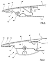
- Fig. 2 is an extruded section 15 for the area the roof top 13 shown in cross section as a Hollow profile 16 is formed.
- the front wall area 17 of the hollow profile 16 has a shaped nose 18 on, in the installation position shown from the or multilayer roof skin 2 is overlapped.
- the hollow profile 16 is on its outer circumference with several inwards Receiving chambers 19, 19 'and an outwardly projecting Holding web 20 provided so that with these profile parts respective pairings of connections to the roof skin 2 or these associated holding parts 23, 23 'are formed. in the The area of the holding part 23 'is towards the interior of the Vehicle facing roof skin part 2 'set.
- the hollow profile 16 is similar to FIG. 2 in one illustrated second embodiment, being in addition to the receiving chambers 19, 19 ', 20' for the roof skin connection a receiving chamber 21 for fixing a cover part 22 is provided and the nose 18 a weight-reducing Has cavity 21 '.
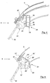
- Extruded profile part 24 in a cross-sectional view illustrates, this extruded section 24 is designed as a U-profile 25 that in the installation position shown by a base leg 26 and two downward holding legs 27, 28 encompassed Receiving chamber 29 has.
- an elastic sealing profile 31 is engaged, on which a side window 32 rests in the closed position.
- FIG. 5 shows a second embodiment of the U-profile 25 ' shown, this respective holding leg 27 ', 28' has, each as a fork with two tines 30, 30 'for supporting the elastic sealing profile body 31 'are formed.
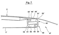
- FIG. 7 is an extruded profile part 46 in the area of rear roof main bow 47 (Fig. 1) shown, wherein this extruded profile part 46 from a hollow profile 48 is formed in the wall as a receiving chamber Annular groove 49 is provided with a receiving slot 50.
- the Hollow profile 48 has a cross-sectional contour that starting from a straight base wall part 51 into a Support the roof skin 2 in the installation position shown arcuate support wall portion 52 merges.
- Execution is the roof main bow 47 with two hollow profiles 48, 48 'provided in the area of their base wall parts 51, 51 'lie against each other.
- Extruded profile parts 15, 24, 35, 46 of the lightweight convertible top frame 1 extensive integration of functions can be achieved that in addition to the connection pairings shown a mounting or fastening of parts of the convertible top cover, of cladding parts, sealing parts, upholstery parts and the like, is possible. It is also conceivable that Extruded profile parts and the connection pairs described above to be designed in such a way that complex adhesive connections a quick replacement of the are avoided Individual components are possible to process fewer individual parts and thus the specific weight of the convertible top frame with sufficient torsional stiffness overall is advantageous to reduce.
- roof bow 47 In the closed position of the convertible top frame 1 is based on rear roof bow 47 also the front area of the Roof roof skin 2 of two are essentially parallel roof bows 60 extending to the roof part 13 and 61 (Fig. 1) so that when closed Driving style of the Cabriolet vehicle a contoured fit Definition of the roof skin 2 in the longitudinal and transverse directions is reached.
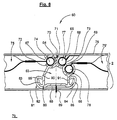
- roof bow 60 and 61 are also provided as extruded profiles as in the inner contour area their cross section (Fig. 8) having a free space Hollow profile parts 63 are formed (Fig. 8 to Fig. 11).
- the hollow profile 63 has 8 on the outer circumference three substantially annular Receiving chambers 64, 65 and 66 with respective receiving slots 67, 68 and 69, this cross-sectional view illustrates that the hollow profile part 63 with on the one hand in the installation position the convertible top roof skin 2 is provided below the T-shaped support area 70, the middle leg 71, on the other hand, two attachment arches 72, 73, which is part of the substantially symmetrically arranged Receiving chambers 64 and 65 are.
- In the reception chamber 64 is connected to a cushion mat 75 first clamping keder 74 supported and in the receiving chamber 65 engages one that is fixed directly on the convertible top cover 76 Clamping welt 77 a.
- the third receiving chamber 66 In the vicinity of the second receiving chamber 65 is in the wall contour of the hollow profile part 63, the third receiving chamber 66 provided, in which a third, on the rear pad area 75 'attacking clamping keder 78 introduced is.
- This triple welt-groove connection enables one quick assembly of the roof skin 2 on the roof bow 47, 60, 61 and also disassembly of the roof skin 2, for example for a separate change of individual parts of the Convertible top frame 1, is after loosening the clamping piping advantageous little effort and without material destruction possible.
- the cross-sectional geometry of the hollow profile part 63 is in an inexpensive continuous casting or extrusion manufacturing producible, so that the roof bow 47, 60, 61 via the plug connections in the area of the clamping piping 74, 77, 70 without additional material expenditure with the Roof skin 2 are connectable. About this connection are, for example, adhesives or the like, unnecessary as a lanyard.
- connection areas Materials of the roof skin 2, for example coated textiles for convertible top cover 76 and / or PVC profiles in the area of the clamping strips 74, 77 and 78, each optimally selected so that when loaded multilayer roof skin 2 even with extremely different climate conditions a long service life is reached that alternating effects of high tensile and compressive forces in the Connection areas causes no material fatigue and so that this connection construction compared to conventional Adhesive connections overall is improved.
- the hollow profile 63 is in its installed position on the vehicle interior 79 facing bottom with a connecting profile 80 provided at least one with the Inner sky 81 connected counter member 82 can be fixed.
- the connection profile 80 is a suitable design two curved hook parts 83, 84 provided, on which the counter member 82 with respective locking legs 85, 86 is supported.
- the counter member 82 is in an appropriate embodiment on Inner headlining 81 is established via a connecting seam 89.
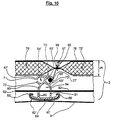
- FIG. 9 to 11 are further advantageous embodiments of the hollow profile part 63 'according to the invention, 63 '', 63 '' 'shown, these at a distance H to the top fabric 76 in the top roof skin 2 are integrated, one below the pad 75, 75 'located cover position is reached.
- the closed position of the convertible top frame 1 is thus the Top fabric 76 not on T-shaped support area 70 the hollow profile parts 63 ', 63' ', 63' '' placed so that unwanted deformations in the form of a roof bow 47, 60, 61 post-forming corrugation with sufficient security are avoided and the optimal overall impression of Roof skin 2 by a uniformly flat top cover 76 is determined.
- the hollow profile part 63 ' accordinging to FIG. 9 has in the area of Connecting profile 80 ', the third receiving chamber 66', in this one connected to the headliner 81 Clamping keder 78 'is fixed.
- the receiving chamber 64 ' is in this embodiment shown subject to change, whereby is conceivable here another fastener in Slide in longitudinal direction of the receiving chamber 64 '.
- connection areas the roof skin 2 or its individual layers with the Hollow profile parts 63 ', 63' 'and 63' '' are in their vicinity respective zipper parts 95 (Fig. 9 to 11) and 96 (Fig. 11) provided with which both the assembly as also the disassembly of the fastening connections shown is further improved with little effort.
- the zipper part 95 on the one hand via a connecting seam 97 on Convertible top cover 76 and on the other hand via a connecting seam 98 connected to the clamping keder 77 '.
- the embodiment 11 has both the zipper part 95 as well as a second zipper part 96, this over a connecting seam 98 the headliner 81 in a tight installation position with the clamping edge 74 'on the double-chamber hollow profile part 63 '' '.
- the above-described keder-groove connections are more expedient Version with continuous in the longitudinal direction of the profile Receiving slots 67, 68, 69; 67 ', 68', 69 ', 67' ', 68' ' provided, which is also conceivable, the respective Hollow profile parts in the longitudinal direction with areas Slots (not shown) to be provided in the over appropriate opening extensions inserted the clamping keder and a longitudinal shift in the intended installation position can be positioned.
Landscapes
- Engineering & Computer Science (AREA)
- Mechanical Engineering (AREA)
- Body Structure For Vehicles (AREA)
Description
Die Erfindung betrifft ein Cabriolet-Fahrzeug mit einem das Faltverdeck tragenden Verdeckgestell gemäß dem Oberbegriff des Anspruchs 1.The invention relates to a convertible vehicle with a Folding hood carrying convertible top frame according to the preamble of claim 1.
Bei bekannten Cabriolet-Fahrzeugen gemäß dem Oberbegriff des Ansprunchs 1 (GB-A-0 656 225) ist die Verdeckgestell-Baugruppe aus einer Vielzahl von verschraubten Einzelteilen gebildet, die in einstückiger Ausführung als stranggepreßte Metallteile mit einem Nutprofil versehen sind, das zur Aufnahme von zusätzlichen Halteleisten vorgesehen ist. Die Montage dieser Einzelteile mit einer Verdeck-Dachhaut ist bei einer Vielzahl von Verbindungspaarungen, insbesondere Schraub- und Nagelverbindungen, überaus aufwendig.In known convertible vehicles according to the preamble of Claim 1 (GB-A-0 656 225) Convertible top frame assembly from a variety of screwed Individual parts formed in one piece as extruded metal parts with a groove profile are provided, to accommodate additional retaining strips is provided. The assembly of these items with a Convertible top roof skin is in a variety of connection pairs, especially screw and nail connections, extremely complex.
Der Erfindung liegt die Aufgabe zugrunde, ein Cabriolet-Fahrzeug der im Oberbegriff des Anspruchs 1 genannten Art zu schaffen, dessen Verdeckgestell mit Einzelbauteilen versehen ist, die bei reduziertem Gewicht eine insgesamt vereinfachte Montage sowie hinreichend stabile Aufnahme der Faltverdeck-Dachhaut im Bereich jeweiliger Verbindungsteile ermöglichen, derart, daß das Dach in Schließstellung im Bereich der Dachspriegel eine gleichmäßige Dachkontur darbietet.The invention has for its object a convertible vehicle that mentioned in the preamble of claim 1 Art to create, the convertible top frame with individual components is provided, which is a total at reduced weight simplified assembly and sufficiently stable mounting of the Folding roof roof skin in the area of the respective connecting parts allow such that the roof in the closed position in Area of the roof bow a uniform roof contour offers.
Ausgehend von einem Cabriolet-Fahrzeug nach dem Oberbegriff
des Anspruchs 1 löst die Erfindung diese Aufgabe mit den
Merkmalen des kennzeichnenden Teils des Anspruchs 1. Hinsichtlich
wesentlicher weiterer Ausgestaltungen wird auf
die Ansprüche 2 bis 28 verwiesen.Starting from a convertible vehicle according to the generic term
of claim 1, the invention solves this problem with
Features of the characterizing part of claim 1. Regarding
essential further developments will be on
referred to
Das erfindungsgemäß ausgebildete Verdeckgestell weist im Bereich der Strangpreßprofilteile jeweils eine Querschnittsgeometrie auf, die mit einer auf geringen Materialverbrauch gerichtete Hohlraumstruktur bei verbesserter Stabilität insgesamt eine Gewichtsreduzierung des Verdeckgestells gewährleistet, wobei gleichzeitig die Strangpreßprofilteile mit jeweiligen Aufnahmeprofilierungen und/oder Hinterschneidungen im Querschnitt versehen sind, so daß damit für entsprechende Gegenglieder von zugeordneten Bauteilen und/oder Verbindungsteilen der Dachhaut überaus einfach montierbare Verbindungsbereiche geschaffen sind.The convertible top frame designed according to the invention has in Area of the extruded profile parts each have a cross-sectional geometry on that with a low material consumption directed cavity structure with improved Overall stability, a reduction in weight of the convertible top frame guaranteed, while at the same time the extruded profile parts with respective admission profiles and / or undercuts are provided in cross section, so that for corresponding counterparts of assigned Components and / or connecting parts of the roof skin extremely easy to assemble connection areas created are.
Die Strangpreßprofile können bei niedrigen Herstellungskosten mit geringem Aufwand an unterschiedliche Stütz- und Haltebedingungen, insbesondere im Bereich der Verbindungspaarungen bei der Dachhaut-Montage, angepaßt werden. Dabei sind in der Querschnittsgeometrie der Strangpreßprofilteile jeweilige Kanäle und Öffnungen zum Befestigen von Dichtungen oder dergleichen so integriert, daß zusätzliche Bearbeitungsschritte vor der Montage weitgehend entbehrlich sind oder gänzlich eingespart werden. The extruded profiles can be manufactured at low cost with little effort to different support and Holding conditions, especially in the area of connection pairings when installing the roof skin. there are in the cross-sectional geometry of the extruded profile parts respective channels and openings for attaching Seals or the like integrated so that additional Processing steps before assembly largely unnecessary are or are saved entirely.
In vorteilhafter Ausführung der Dachspriegel sind in der Wandungskontur des einen Hohlprofil-Querschnitt aufweisenden Strangpreßprofilteils mehrere Aufnahmekammern mit schlitzförmigen Aufnahmeöffnungen vorgesehen, über die jeweilige mit der Verdeck-Dachhaut und/oder dem inneren Dachhimmel verbundene Klemmkeder derart in die Aufnahmekammer einführbar sind, daß die Klemmkeder in dieser Einbaulage über einen formschlüssigen Verbindungseingriff hinreichend stabil am Dachspriegel festgelegt sind und die Dachhaut insgesamt über eine in Schließstellung deren Konturform vorgebenden Abstützung spannbar ist. Gleichzeitig sind jeweilige zur Dachhaut gerichtete Verbindungsbereiche der Klemmkeder so im Aufnahmeschlitz geführt, daß eine weitgehend freie Beweglichkeit bei Entspannung der Dachhaut erreicht ist und damit Belastungsveränderungen im Bereich der Klemmkeder bzw. der Dachhaut, insbesondere bei häufigen Wiederholungen von Öffnungs- bzw. Schließbewegungen des Verdeckgestells, über eine Bewegung der Klemmkeder ausgeglichen werden. In diesem Verbindungsbereich sind Überbelastungen vermieden und damit ist die Langzeitstabilität der Dachhaut-Anbindung im Bereich der Dachspriegel insgesamt verbessert. Die Klemmkeder können dabei im Bereich der Dachspriegel überaus einfach montiert und demontiert werden.In an advantageous embodiment, the roof bow are in the Wall contour of the one having a hollow profile cross section Extruded profile part with several receiving chambers slit-shaped receiving openings provided over the each with the convertible top roof skin and / or the inner Headliner connected to the headlining in the receiving chamber are insertable that the clamping piping in this position sufficient via a positive connection intervention are firmly attached to the roof bow and the Roof skin overall over a contour shape in the closed position the given support can be clamped. At the same time are respective connection areas facing the roof skin the clamping strip is guided in the receiving slot so that a largely free mobility when relaxing the roof membrane is reached and thus changes in the load the clamping piping or the roof skin, especially for frequent ones Repetitions of opening and closing movements of the Convertible top frame, balanced by a movement of the clamping piping become. There are overloads in this connection area avoided and thus long-term stability the roof skin connection in the area of the roof bow overall improved. The clamping piping can be in the area the roof bow is extremely easy to assemble and disassemble become.
Auf seiner zum Fahrzeuginnenraum gerichteten Unterseite ist das Hohlprofilteil ebenfalls mit einer Verbindungsprofilierung versehen, an der ein mit dem Innenhimmel verbundenes Gegenglied oder ein Klemmkeder lösbar festlegbar ist, so daß auch dieser Verbindungsbereich insgesamt überaus einfach montierbar und für eine Demontage, beispielsweise bei einem Wechsel der Dachhaut und/oder des Innenhimmels, geeignet ist.On its underside facing the vehicle interior the hollow profile part also with a connection profile provided on the one connected to the headliner Counter member or a clamping keder is releasably fixable, so that this connection area as a whole is extremely simple mountable and for disassembly, for example at a change in the roof skin and / or the headlining, suitable is.
In vorteilhafter Weiterbildung des Hohlprofilteils kann dieses, beispielsweise in seiner Bauteilhöhe, für verschiedene Dachhautstrukturen variabel gestaltet werden, so daß das Hohlprofilteil ohne unmittelbare Anlage- oder Verbindungsflächen am oberen Verdeckbezug in einen Freiraum zwischen der Polstermatte und dem Innenhimmel integrierbar ist. In Schließstellung des Verdeckgestells weist so die Dachhaut eine gleichmäßig ebene Kontur ohne im Bereich der Dachspriegel sichtbare Erhebungen oder Wellenformen auf, so daß der optische Gesamteindruck des Cabriolet-Fahrzeugs insgesamt verbessert ist.In an advantageous development of the hollow profile part this, for example in its component height, for different Roof skin structures can be designed variably, so that the hollow profile part without direct contact or connection surfaces in a free space on the top cover can be integrated between the upholstered mat and the headlining is. In the closed position of the convertible top frame, the Roof skin a uniformly flat contour without in the area of Roof bows visible elevations or waveforms, so that the overall visual impression of the Cabriolet vehicle is improved overall.
Weitere Einzelheiten und Vorteile der Erfindung ergeben sich aus der nachfolgenden Beschreibung und der Zeichnung, die ein Ausführungsbeispiel des Gegenstands der Erfindung schematisch veranschaulicht. In der Zeichnung zeigen:
- Fig. 1
- eine perspektivische Einzeldarstellung des erfindungsgemäßen Verdeckgestells mit den Tragwerksbauteilen in Schließstellung,
- Fig. 2
- eine Ausschnittsdarstellung eines im Bereich des Dachspitzenteils vorgesehenen Strangpreßprofilteils gemäß einer Linie II-II in Fig. 1 in einer ersten Ausführungsform,
- Fig. 3
- eine Ausschnittsdarstellung der Dachspitze ähnlich Fig. 2 mit dem Strangpreßprofilteil in einer zweiten Ausführungsform,
- Fig. 4
- eine Ausschnittsdarstellung eines im Bereich des Seitenrahmens vorgesehenen Strangpreßprofilteils gemäß einer Linie IV-IV in Fig. 1,
- Fig. 5
- eine Ausschnittsdarstellung des Seitenrahmens ähnlich Fig. 4 mit dem Strangpreßprofilteil in einer zweiten Ausführungsform,
- Fig. 6
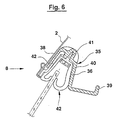
- eine Ausschnittsdarstellung eines Strangpreßprofilteils im Bereich der Hauptsäule gemäß einer Linie VI-VI in Fig. 1,
- Fig. 7
- eine Ausschnittsdarstellung eines Strangpreßprofilteils im Bereichs des Hauptspriegels gemäß einer Linie VI-VI in Fig. 1,
- Fig. 8
- eine Querschnittsdarstellung eines der als Hohlprofilteil ausgebildeten Dachspriegel gemäß einer Linie VIII - VIII in Fig. 1 mit einer Verdeck-Dachhaut in Einbaulage, und
- Fig. 9 bis Fig. 11
- jeweilige Querschnittsdarstellungen ähnlich Fig. 8 mit unterschiedlichen Ausführungsformen der Hohlprofilteile.
- Fig. 1
- 2 shows a perspective individual illustration of the convertible top frame according to the invention with the structural components in the closed position,
- Fig. 2
- 2 shows a detail of an extruded profile part provided in the area of the roof top part according to a line II-II in FIG. 1 in a first embodiment,
- Fig. 3
- 3 shows a detail of the roof top similar to FIG. 2 with the extruded profile part in a second embodiment,
- Fig. 4
- 2 shows a detail of an extruded profile part provided in the region of the side frame according to a line IV-IV in FIG. 1,
- Fig. 5
- 4 shows a detail of the side frame similar to FIG. 4 with the extruded profile part in a second embodiment,
- Fig. 6
- 1 shows a detail of an extruded profile part in the area of the main column according to a line VI-VI in FIG. 1,
- Fig. 7
- 1 shows a detail of an extruded profile part in the region of the main bow according to a line VI-VI in FIG. 1,
- Fig. 8
- a cross-sectional view of one of the roof profile formed as a hollow profile part according to a line VIII - VIII in Fig. 1 with a roof roof skin in the installed position, and
- 9 to 11
- respective cross-sectional representations similar to FIG. 8 with different embodiments of the hollow profile parts.
In Fig. 1 ist ein insgesamt mit 1 bezeichnetes Verdeckgestell
eines nicht näher dargestellten Cabriolet-Fahrzeuges
veranschaulicht, wobei zur Verdeutlichung der wesentlichen
Einzelteile dieser Tragwerkskonstruktion eine diese
überspannende Dachhaut 2 lediglich in den Ausschnittsdarstellungen
gemäß Fig. 2 bis 7 sichtbar ist.In Fig. 1 is a convertible top frame, generally designated 1
a convertible vehicle, not shown
illustrates, with the clarification of the essential
Individual parts of this structure a this
spanning
Das Verdeckgestänge 1 ist mit symmetrisch zur Fahrzeuglängsachse
3 angeordneten sowie aus vorderen und hinteren
Teilstücken 4, 5 bestehenden Seitenrahmenteilen 6, 7 versehen,
die jeweils einenends über eine Hauptsäule 8 und
eine Hauptführungsstange 9 schwenkbeweglich an einem hinteren
Hauptlager 10 der Fahrzeugkarosserie 11 abgestützt
sind. Im vorderen Bereich sind die Seitenrahmenteile 6, 7
über ein in der dargestellten Schließstellung am oberen
Querholm eines Windschutzscheibenrahmens (nicht dargestellt)
anlegbares Dachspitzenteil 13 verbunden.The convertible top linkage 1 is symmetrical to the longitudinal axis of the
Das nachfolgend näher beschriebene Verdeckgestell 1 ist in erfindungsgemäßer Ausbildung als ein aus Strangpreßprofilteilen bestehendes Leichtbautragwerk ausgebildet, dessen Einzelbauteile ganz ober überwiegend aus Aluminium bestehen. Dabei sind die Strangpreßprofilteile in ihrer Querschnittskontur zumindest teilweise mit einem Aufnahmeprofil versehen, so daß bei der Montage der Verdeck-Dachhaut 2 und/oder von Gestängeteilen ein entsprechendes Halteteil in eine Verbindungsstellung verbringbar ist.The convertible top frame 1 described in more detail below is in Training according to the invention as an extruded profile parts existing lightweight structure, whose Individual components are made entirely of aluminum. The extruded profile parts are in their cross-sectional contour at least partially with an admission profile provided so that when installing the convertible top roof skin 2nd and / or a corresponding holding part of rod parts a connection position can be brought.
In Fig. 2 ist ein Strangpreßprofilteil 15 für den Bereich
der Dachspitze 13 dargestellt, das im Querschnitt als ein
Hohlprofil 16 ausgebildet ist. Der vordere Wandungsbereich
17 des Hohlprofils 16 weist dabei eine Formnase 18
auf, die in der dargestellten Einbaulage von der ein- oder
mehrlagigen Dachhaut 2 übergriffen ist. Das Hohlprofil 16
ist an seinem Außenumfang mit mehreren nach innen gerichteten
Aufnahmekammern 19, 19' und einem nach außen vorstehenden
Haltesteg 20 versehen, so daß mit diesen Profilteilen
jeweilige Verbindungspaarungen zur Dachhaut 2 bzw.
dieser zugeordneten Halteteilen 23, 23' gebildet werden. Im
Bereich des Halteteiles 23' ist dabei ein zum Innenraum des
Fahrzeugs gerichtetes Dachhautteil 2' festgelegt.In Fig. 2 is an
In Fig. 3 ist das Hohlprofil 16 ähnlich Fig. 2 in einer
zweiten Ausführungsform dargestellt, wobei zusätzlich zu
den Aufnahmekammern 19, 19', 20' für die Dachhautanbindung
eine Aufnahmekammer 21 zur Festlegung eines Abdeckteiles 22
vorgesehen ist und die Formnase 18 einen gewichtsreduzierenden
Hohlraum 21' aufweist.3, the
In Fig. 4 ist ein für den Bereich des Seitenrahmens 6 vorgesehenes
Strangpreßprofilteil 24 in einer Querschnittsdarstellung
veranschaulicht, wobei dieses Strangpreßprofilteil
24 als ein U-Profil 25 ausgebildet ist, daß in der
dargestellten Einbaulage eine von einem Basisschenkel 26
und zwei nach unten gerichteten Halteschenkeln 27, 28 umgriffene
Aufnahmekammer 29 aufweist. In der Aufnahmekammer
29 ist ein elastisches Dichtungsprofil 31 eingerastet,
an dem in Schließstellung eine Seitenscheibe 32 anliegt.4 is provided for the area of the
Zur Erhöhung der Stabilität des U-Profils 25 ist dieses im
Bereich seines Basisschenkels 26 mit einem in Längsrichtung
eine Profilaussteifung bewirkenden Hohlprofilansatz 33
versehen, so daß mit geringem konstruktivem Aufwand das
Strangpreßprofilteil 24 bei geringer Wandstärke eine hohe
Steifigkeit aufweist.To increase the stability of the U-profile 25, this is in
Area of its
In Fig. 5 ist eine zweite Ausführungsform des U-Profils 25'
dargestellt, wobei dieses jeweilige Halteschenkel 27', 28'
aufweist, die jeweils als eine Gabel mit zwei Profilzinken
30, 30' zur Abstützung des elastischen Dichtungsprofilkörpers
31' ausgebildet sind.5 shows a second embodiment of the U-profile 25 '
shown, this respective holding leg 27 ', 28'
has, each as a fork with two
In Fig. 6 ist ein Strangpreßprofilteil 35 im Bereich der
Hauptsäule 8 dargestellt, wobei dieses Teil 35 von einem
einen gemeinsamen Mittelsteg 36 aufweisenden Doppel-U-Profil
mit gegensinnig abragenden Außenschenkeln 38, 39
gebildet ist, wobei in einer in der dargestellten Einbaulage
äußeren Aufnahmekammer 40 eine als elastisches Dichtungsprofil
ausgebildete Seitenscheibenhalterung 42 über
eine Schraubverbindung 41 festgelegt ist. Zur Festlegung
der Dachhaut 2 ist in die Aufnahmekammer 40 zusätzlich ein
den Endbereich der Dachhaut 2 erfassendes Stützteil 42 eingebracht.6 is an extruded
In Fig. 7 ist ein Stangpreßprofilteil 46 im Bereich des
hinteren Dachhauptspriegels 47 (Fig. 1) dargestellt, wobei
dieses Strangpreßprofilteil 46 von einem Hohlprofil 48
gebildet ist, in dessen Wandung als Aufnahmekammer eine
Ringnut 49 mit einem Aufnahmeschlitz 50 vorgesehen ist. Das
Hohlprofil 48 weist dabei eine Querschnittskontur auf, die
ausgehend von einem geraden Basiswandteil 51 in einen die
Dachhaut 2 in der dargestellten Einbaulage abstützenden
bogenförmigen Stützwandteil 52 übergeht. In zweckmäßiger
Ausführung ist der Dachhauptspriegel 47 mit zwei Hohlprofilen
48, 48' versehen, die im Bereich ihrer Basiswandteile
51, 51' aneinanderliegen.7 is an extruded
Mit den vorbeschriebenen Ausführungsformen der Strangpreßprofilteile
15, 24, 35, 46 des Leichtbau-Verdeckgestells 1
ist eine weitgehende Funktionsintegration derart erreichbar,
daß zusätzlich zu den dargestellten Verbindungspaarungen
eine Aufnahme bzw. Befestigung von Teilen des Verdeckbezuges,
von Verkleidungsteilen, Dichtungsteilen, Polsterteilen
und dgl., möglich ist. Ebenso ist denkbar, die
Strangpreßprofilteile und die vorbeschriebenen Verbindungspaarungen
derart zu gestalten, daß aufwendige Klebeverbindungen
vermieden sind, eine schnelle Auswechselung der
Einzelbauteile möglich ist, weniger Einzelteile zu verarbeiten
sind und damit das spezifische Gewicht des Verdeckgestells
bei hinreichender Verwindungssteife insgesamt
vorteilhaft zu verringern ist.With the above-described embodiments of the extruded
In Schließstellung des Verdeckgestells 1 ist ausgehend vom
hinteren Dachhauptspriegel 47 auch der vordere Bereich der
Verdeckdachhaut 2 von zwei sich im wesentlichen parallel
zum Dachspitzenteil 13 erstreckenden Dachspriegeln 60
und 61 (Fig. 1) derart untergriffen, daß bei geschlossener
Fahrweise des Cabriolet-Fahrzeugs eine konturstraffe
Festlegung der Dachhaut 2 in Längs- und Querrichtung
erreicht ist. Diese Dachspriegel 60 und 61 sind ebenfalls
als Strangpreßprofile vorgesehen, die als im inneren Konturbereich
ihres Querschnitts (Fig. 8) einen Freiraum aufweisende
Hohlprofilteile 63 ausgebildet sind (Fig. 8 bis
Fig. 11).In the closed position of the convertible top frame 1 is based on
Das Hohlprofil 63 weist in einer ersten Ausführungsform
gemäß Fig. 8 am Außenumfang drei im wesentlichen ringförmige
Aufnahmekammern 64, 65 und 66 mit jeweiligen Aufnahmeschlitzen
67, 68 und 69 auf, wobei diese Querschnittsdarstellung
verdeutlicht, daß das Hohlprofilteil 63 mit
einem einerseits in Einbaulage die Verdeck-Dachhaut 2
untergreifenden T-förmigen Stützbereich 70 versehen ist,
dessen Mittelschenkel 71 andererseits zwei Ansatzbögen 72,
73 aufweist, die Teil der im wesentlichen symmetrisch angeordneten
Aufnahmekammern 64 und 65 sind. In der Aufnahmekammer
64 ist dabei ein mit einer Polstermatte 75 verbundener
erster Klemmkeder 74 abgestützt und in die Aufnahmekammer
65 greift ein unmittelbar am Verdeckbezug 76 festgelegter
Klemmkeder 77 ein.In a first embodiment, the
Im Nahbereich der zweiten Aufnahmekammer 65 ist in der Wandungskontur
des Hohlprofilteils 63 die dritte Aufnahmekammer
66 vorgesehen, in der ein dritter, am rückwärtigen Polstermattenbereich
75' angreifender Klemmkeder 78 eingeführt
ist.In the vicinity of the second receiving
Diese dreifache Keder-Nut-Verbindung ermöglicht eine
schnelle Montage der Dachhaut 2 an den Dachspriegeln 47,
60, 61 und auch eine Demontage der Verdeck-Dachhaut 2, beispielsweise
zu einem separaten Wechsel von Einzelteilen des
Verdeckgestells 1, ist nach einem Lösen der Klemmkeder mit
vorteilhaft geringem Aufwand und ohne Materialzerstörung
möglich. Die Querschnittsgeometrie des Hohlprofilteils 63
ist in einer kostengünstigen Stranguß- oder Strangzieh-Fertigung
herstellbar, so daß danach die Dachspriegel 47,
60, 61 über die Steckverbindungen im Bereich der Klemmkeder
74, 77, 70 ohne zusätzliche Materialaufwendungen mit der
Dachhaut 2 verbindbar sind. Zu dieser Verbindungsherstellung
sind beispielsweise Klebstoffe oder dgl.,
als Verbindungsmittel entbehrlich.This triple welt-groove connection enables one
quick assembly of the
Gleichzeitig sind die für die Verbindungsbereiche vorgesehenen
Materialien der Verdeck-Dachhaut 2, beispielsweise
beschichtete Textilien für den Verdeckbezug 76 und/oder
PVC-Profile im Bereich der Klemmkeder 74, 77 und 78,
jeweils optimal so ausgewählt, daß bei Belastung dieser
mehrlagigen Dachhaut 2 auch bei extrem unterschiedlichen
Klimagegebenheiten eine hohe Lebensdauer erreicht ist, die
wechselnde Einwirkung hoher Zug- und Druckkräfte in den
Verbindungsbereichen keine Materialermüdungen bewirkt und
damit diese Verbindungskonstruktion gegenüber herkömmlichen
Klebeverbindungen insgesamt verbessert ist.At the same time, those are provided for the connection areas
Materials of the
Das Hohlprofil 63 ist auf seiner in Einbaulage zum Fahrzeuginnenraum
79 gerichteten Unterseite mit einem Verbindungsprofil
80 versehen, an dem zumindest ein mit dem
Innenhimmel 81 verbundenes Gegenglied 82 festlegbar ist. In
zweckmäßiger Ausführung ist das Verbindungsprofil 80 mit
zwei bogenförmig nach oben verlaufenden Hakenteilen 83, 84
versehen, an denen das Gegenglied 82 mit jeweiligen Rastschenkeln
85, 86 abgestützt ist.The
Im Bereich dieser Verbindung des Innenhimmels 81 weist das
Hohlprofil 63 zum Gegenglied 82 hin eine dessen Anlagefläche
am Innenhimmel 81 verringernde Nutform 88 auf, so daß
in diesem Anlagebereich eine geringfügige Lageverschiebung
des Innenhimmels 81 über das Gegenglied 82 aufnehmbar ist.
Das Gegenglied 82 ist in zweckmäßiger Ausführung am
Innenhimmel 81 über eine Verbindungsnaht 89 festgelegt.In the area of this connection of the
In Fig. 9 bis Fig. 11 sind weitere vorteilhafte Ausführungsformen
des erfindungsgemäßen Hohlprofilteils 63',
63'', 63''' dargestellt, wobei diese in einem Abstand H zu
dem oberseitigen Verdeckstoff 76 derart in die Verdeck-Dachhaut
2 integriert sind, daß eine unterhalb der Polstermatte
75, 75' befindliche Abdeckstellung erreicht ist. In
der Schließstellung des Verdeckgestells 1 ist damit der
Verdeckstoff 76 nicht auf dem T-förmigen Stützbereich 70
der Hohlprofilteile 63', 63'', 63''' aufgelegt, so daß
ungewollte Deformationen in Form einer die Dachspriegel 47,
60, 61 nachformenden Wellung mit hinreichender Sicherheit
vermieden sind und der optimale Gesamteindruck der
Dachhaut 2 durch einen gleichmäßig ebenen Verdeckbezug 76
bestimmt ist.9 to 11 are further advantageous embodiments
of the hollow profile part 63 'according to the invention,
63 '', 63 '' 'shown, these at a distance H to
the
Das Hohlprofilteil 63' gemäß Fig. 9 weist im Bereich des
Verbindungsprofils 80' die dritte Aufnahmekammer 66' auf,
wobei in dieser ein mit dem Dachhimmel 81 verbundener
Klemmkeder 78' festgelegt ist. Die Aufnahmekammer 64' ist
in dieser Ausführungsform freibleibend dargestellt, wobei
denkbar ist, hier ein weiteres Befestigungselement in
Längsrichtung der Aufnahmekammer 64' einzuschieben.The hollow profile part 63 'according to FIG. 9 has in the area of
Connecting profile 80 ', the third receiving chamber 66',
in this one connected to the
In sämtlichen Ausführungsformen des Hohlprofilteils 63,
63', 63'', 63''' ist das Verbindungsprofil 80, 80' über
zwei im wesentlichen parallele Verbindungsschenkel 90, 91
mit dem unteren Wandungsbereich der Aufnahmekammer 64, 65
bzw. 64', 65' verbunden. In den Ausführungsformen gemäß
Fig. 9 und Fig. 10 sind die Verbindungsschenkel 90, 91 mit
jeweiligen Durchlaßöffnungen 93, 94 versehen, so daß in
diesem Bereich ein Spanngurt 92 als zusätzliches Sicherungs-
und Aussteifungsteil in die Verdeckkonstruktion
integriert werden kann.In all embodiments of the
In einer weiteren zweckmäßigen Ausbildung der Verbindungsbereiche
der Dachhaut 2 bzw. deren Einzellagen mit den
Hohlprofilteilen 63', 63'' und 63''' sind in deren Nahbereich
jeweilige Reißverschlußteile 95 (Fig. 9 bis 11) und
96 (Fig. 11) vorgesehen, mit denen sowohl die Montage als
auch die Demontage der dargestellten Befestigungsanbindungen
mit geringem Aufwand weiter verbessert ist. Bei der
Erstmontage der jeweiligen Klemmkeder 74, 77, 78; 74'; 77',
78' werden diese beispielsweise in Längsrichtung der
Dachspriegel 47, 60, 61 in die vorbeschriebenen Aufnahmekammern
eingeschoben, so daß danach mit einer die Aufnahmeschlitze
durchgreifenden Verbindungsfahne die Klemmkeder in
der dargestellten Form mit den Polstermatten 75, 75' bzw.
den Reißverschlüssen 95, 96 verbunden werden können. In
diesen Verbindungsbereichen sind in zweckmäßiger Ausführung
Schweißnähte (HF-Schweißung) vorgesehen und bei der Montage
bzw. Demontage sind Teilbereiche der Dachhaut 2 durch die
einfach zu verbindenden bzw. zu lösenden Reißverschlußteile
95, 96 problemlos zugänglich.In a further expedient design of the connection areas
the
In den Ausführungsformen gemäß Fig. 9 und 10 ist das Reißverschlußteil
95 einerseits über eine Verbindungsnaht 97 am
Verdeckbezug 76 festgelegt und andererseits über eine Verbindungsnaht
98 mit dem Klemmkeder 77' verbunden. Die Ausführungsform
gemäß Fig. 11 weist sowohl das Reißverschlußteil
95 als auch ein zweites Reißverschlußteil 96 auf,
wobei dieses über eine Verbindungsnaht 98 den Innenhimmel
81 in straffer Einbaulage mit dem Klemmkeder 74' am Doppelkammer-Hohlprofilteil
63''' festlegt.In the embodiments according to FIGS. 9 and 10, the
Die vorbeschriebenen Keder-Nut-Verbindungen sind in zweckmäßiger
Ausführung mit in Profillängsrichtung durchlaufenden
Aufnahmeschlitzen 67, 68, 69; 67', 68', 69', 67'', 68''
versehen, wobei ebenfalls denkbar ist, die jeweiligen
Hohlprofilteile in Längsrichtung mit bereichsweisen
Schlitzen (nicht dargestellt) zu versehen, in die über
entsprechende Öffnungserweiterungen die Klemmkeder eingeschoben
und über eine Verschiebung in Längsrichtung in die
vorgesehene Einbaulage positioniert werden können.The above-described keder-groove connections are more expedient
Version with continuous in the longitudinal direction of the
Claims (28)
- A convertible vehicle of which preferably a roof frame (1) carrying a foldable top roof skin (2) has, disposed symmetrically in relation to the longitudinal axis (3) of the vehicle, and consisting of front and rear partial members (4, 5), lateral frame parts (6, 7), each of which is supported at one end by a main pillar (8) and a main guide rod (9) for pivoting movement on a rear main mounting (10) on the vehicle body (11), while its other end is connected via a roof ridge part (13) which can, when in its closed position, be applied against the upper transverse strut of a windscreen frame, the roof frame (1) consisting of extruded section parts (15; 24; 35; 46; 60; 61), characterised in that the extruded section parts (15; 24; 35; 46; 60; 61) are at least partially constructed with accommodating profiled parts forming housing chambers (19, 19'; 20', 21; 29, 29'; 40; 49, 49'; 64, 5, 66) and/or retaining webs (20; 27, 28; 38, 39; 83, 84) on which respective mating members (23, 23'; 74, 77, 78) on the roof skin (2) and/or associated components (22; 31; 31'; 80) can be locked by a positive connecting engagement.
- A convertible vehicle according to claim 1, characterised in that the extruded section parts (15; 24; 35; 46; 60; 61) and/or the mating member provided as a retaining part (23') have a back taper.
- A convertible vehicle according to claim 1 or 2, characterised in that the extruded section parts (15; 24; 35; 46; 50; 61) form a lightweight supporting structure consisting wholly or predominantly of aluminium.
- A folding top according to one of claims 1 to 3, characterised in that the extruded section part (15) for the region of the roof ridge (13) is in cross-section constructed as a hollow profiled member (16) of which the wall (17) forming a front shaped nose (18) has a single-ply or multi-ply roof skin (2) engaging over it when in the installed state.
- A convertible vehicle according to claim 4, characterised in that the hollow profiled member (16) has on its outer periphery a plurality of inwardly directed accommodating chambers (19, 19'; 202; 21) and/or outwardly projecting retaining webs (20).
- A convertible vehicle according to one or more of claims 1 to 4, characterised in that the extruded section parts (24) in the region of the lateral frame (6, 7) are respectively constructed as channel sections (25; 25';) which, in the erected state, form an accommodating chamber (29; 29') around which engage a base member (26; 26') and two downwardly directed retaining members (27, 28; 27', 28').
- A convertible vehicle according to claim 6, characterised in that the channel section (25) is in the region of its base member (26) provided with a hollow profiled extension piece (33) which strengthens it in the longitudinal direction.
- A convertible vehicle according to claim 6 or 7, characterised in that the retaining members (27', 28') are respectively formed as fork with two profiled tines (30, 30').
- A convertible vehicle according to one or more of claims 1 to 8, characterised in that the extruded section part (35) is, in the region of the main pillar (8), formed by a double channel section with a common central web (36) and with oppositely projecting outer members (38, 39) and in that the accommodating chamber (40) which is on the outside in the erected state is provided with a side window support (42).
- A convertible window according to one or more of claims 1 to 9, characterised in that the extruded section part (46) is, in the region of a rear main roof strut (47), formed by a hollow profiled member (48; 48') in the wall of which there is an annular groove (49; 49') with a receiving slot (50; 50') which constitutes an accommodating chamber.
- A convertible vehicle according to claim 10, characterised in that the hollow profiled part (48; 48') has a cross-sectional contour which, starting from a straight base wall part (51; 51') merges into an arcuate bracing wall part (52; 2') which, in the erected state, supports the roof skin (2).
- A convertible vehicle according to claim 10 or 11, characterised in that in the erected state the main roof strut (47) has two hollow profiled members (48; 48') which bear on each other in the region of their base wall parts (51; 51').
- A convertible vehicle according to one or more of claims 1 to 12, characterised in that at least one of the front roof struts (60, 61) is constructed as a one-piece multichamber hollow profiled part (63; 63'; 63''; 63'''), which has at least two substantially annular accommodating chambers (64, 65, 66; 64', 64', 66') with in each case at least one accommodating slot (67, 68, 69; 67', 68', 69'; 67", 68").
- A convertible vehicle according to claim 13, characterised in that in each of the accommodating chambers (64, 65, 66; 64', 65', 66') there is a clamping strip (74, 77, 78; 74', 77', 78') engaging the roof trim (76) and/or a padding (75, 75') connected thereto and/or an inner head lining (81).
- A convertible vehicle according to claim 13 or 14, characterised in that the hollow profiled part (63', 63'', 63''') is integrated into the top roof skin (2) at a distance (H) from an upper roof material (76) in such a way that the hollow profiled part (63'; 63", 63''') assumes a covering position extending under the padding (75, 75').
- A convertible vehicle according to one of claims 13 to 15, characterised in that the hollow profiled part (63; 63'; 63''; 63''') is provided with a T-shaped supporting area (70) of which the middle arm (71) merges at its root into two curved extension pieces (72, 73) which are part of substantially symmetrically disposed accommodating chambers (64, 65; 64', 65').
- A convertible vehicle according to one of claims 13 to 16, characterised in that the hollow profiled part (63) has in the vicinity of its two accommodating chambers (64, 65) a third accommodating chamber (66) in which a clamping strip (78) is fixed which engages a marginal portion of the padding (75').
- A convertible vehicle according to one of claims 13 to 17, characterised in that the hollow profiled part (63; 63") has on its under side which is directed towards the interior of the vehicle (70 when it is in the erected state, a connecting profiled member (80; 80') on which it is possible to fix at least one mating member (82; 82') which is connected to the interior head lining (81).
- A convertible vehicle according to one of claims 13 to 18, characterised in that as the connecting profiled member (80), two arcuately upwardly extending hook-shaped parts (83, 84) are provided on which the one-piece mating member (82) is supported through respective catch arms (85, 86).
- A convertible vehicle according to one of claims 13 to 19, characterised in that the hollow profiled part (63) has in the region of its connection with the mating member (82) a channel-like shape (88) which reduces its contacting surface.
- A convertible vehicle according to one of claims 13 to 20, characterised in that the connecting profiled member (80; 80') is connected to the lower wall area of the accommodating chambers (64, 65; 64', 65') by two substantially parallel connecting arms (90, 91).
- A convertible vehicle according to one of claims 13 to 21, characterised in that the clamping strip (77) which is supported in the middle accommodating chamber (65) of the hollow profiled part (83) is at its other end connected directly to the roof trim (76).
- A convertible vehicle according to one of claims 13 to 22, characterised in that the two outer clamping strips (74, 78) respectively engage parts of the area of the padding (75, 75').
- A convertible vehicle according to one of claims 13 to 23, characterised in that the interior head lining (81) is connected to the mating member (82) via a seam (89).
- A convertible vehicle according to one of claims 13 to 24, characterised in that the hollow profiled part (63') has in the region of the connecting profiled member (80') the third accommodating chamber (66') into which a clamping strip (78') which is connected to the roof head lining (81) engages.
- A convertible vehicle according to one of claims 13 to 25, characterised in that the hollow profiled part (63, 63") has in the region of each of the connecting arms (90, 91) an aperture (93, 94) through which a tensioning strap (92) passes.
- A convertible vehicle according to one of claims 13 to 26, characterised in that the padding (75, 75') and/or the interior head lining (81) is connected to the respective clamping strip (74'; 77') in the vicinity of the hollow profiled part (63'. 63", 63''') by a sliding clasp fastening part (95, 96).
- A convertible vehicle according to one of claims 13 to 27, characterised in that the sliding clasp fastening part (95, 96) is supported on the roof trim (76) or on the interior head lining (81) by a connecting seam (97, 98).
Applications Claiming Priority (4)
| Application Number | Priority Date | Filing Date | Title |
|---|---|---|---|
| DE29607114U | 1996-04-19 | ||
| DE29607114U DE29607114U1 (en) | 1996-04-19 | 1996-04-19 | Cabriolet vehicle |
| DE29702421U DE29702421U1 (en) | 1997-02-13 | 1997-02-13 | Cabriolet vehicle |
| DE29702421U | 1997-02-13 |
Publications (3)
| Publication Number | Publication Date |
|---|---|
| EP0806313A1 EP0806313A1 (en) | 1997-11-12 |
| EP0806313B1 true EP0806313B1 (en) | 2001-08-22 |
| EP0806313B2 EP0806313B2 (en) | 2007-05-02 |
Family
ID=26058873
Family Applications (1)
| Application Number | Title | Priority Date | Filing Date |
|---|---|---|---|
| EP97105887A Expired - Lifetime EP0806313B2 (en) | 1996-04-19 | 1997-04-10 | Vehicle convertible |
Country Status (2)
| Country | Link |
|---|---|
| EP (1) | EP0806313B2 (en) |
| DE (1) | DE59704350D1 (en) |
Cited By (3)
| Publication number | Priority date | Publication date | Assignee | Title |
|---|---|---|---|---|
| EP2409870A2 (en) | 2010-07-20 | 2012-01-25 | Magna Car Top Systems GmbH | Sealing arrangement for a folding roof |
| DE10242451B4 (en) * | 2002-09-11 | 2013-11-28 | Webasto Ag | Hat rack of a convertible |
| DE102015206071A1 (en) | 2015-04-02 | 2016-10-06 | Magna Car Top Systems Gmbh | Adjustable folding top of a convertible vehicle, as well as method for producing a roof cap for an adjustable folding top |
Families Citing this family (16)
| Publication number | Priority date | Publication date | Assignee | Title |
|---|---|---|---|---|
| DE29720065U1 (en) * | 1997-11-12 | 1997-12-18 | Dr.Ing.H.C. F. Porsche Ag, 70435 Stuttgart | Folding hood for a vehicle |
| DE19754189C2 (en) * | 1997-12-06 | 1999-09-30 | Porsche Ag | Folding hood for a vehicle, in particular a passenger car |
| DE19825700A1 (en) * | 1998-06-09 | 1999-12-16 | Volkswagen Ag | Motor vehicle with a convertible roof |
| DE29819187U1 (en) * | 1998-10-28 | 1999-08-12 | Wilhelm Karmann GmbH, 49084 Osnabrück | Motor vehicle with a foldable hood |
| DE19949865A1 (en) * | 1999-10-15 | 2001-04-26 | Parat Automotive Schoenenbach | Folding or folding roof for vehicles such as convertibles or the like. |
| DE19957049A1 (en) * | 1999-11-26 | 2001-06-07 | Parat Automotive Schoenenbach | Convertible top |
| DE20005180U1 (en) * | 2000-03-21 | 2001-03-22 | Wilhelm Karmann GmbH, 49084 Osnabrück | Cabriolet vehicle |
| DE10141312C1 (en) | 2001-08-28 | 2003-05-22 | Cts Fahrzeug Dachsysteme Gmbh | Vehicle roof with a convertible top that can be adjusted between the closed position and the open position |
| DE10201618B4 (en) * | 2002-01-16 | 2007-06-14 | Edscha Cabrio-Dachsysteme Gmbh | Device for fixing a top cloth on parts of a convertible top |
| DE10349822A1 (en) * | 2003-10-24 | 2005-06-02 | Wilhelm Karmann Gmbh | Convertible car |
| US8465081B2 (en) | 2004-02-27 | 2013-06-18 | Magna Car Top Systems Gmbh | Convertible top cover and headliner interconnected by bows |
| JP4636898B2 (en) * | 2005-02-25 | 2011-02-23 | 株式会社東洋シート | Vehicle hood device |
| DE102007021074B3 (en) * | 2007-05-04 | 2008-12-04 | Webasto Ag | Roof module for motor vehicle, has frame profile connected with roof shell and exhibiting base and two brackets that are connected with base, where one bracket exhibits undercut in longitudinal direction |
| DE102007029703A1 (en) | 2007-06-27 | 2009-01-22 | Wilhelm Karmann Gmbh | Cabriolet cover, has cover layer comprising reinforced connection region with recess, which is partially covered with recess of counter support, where cover layer with connection unit is fixed on support by both recesses |
| DE102009018295A1 (en) * | 2009-04-21 | 2010-11-11 | Magna Car Top Systems Gmbh | Folding roof for a passenger car |
| FR2978381B1 (en) | 2011-07-28 | 2013-08-30 | Webasto Systemes Carrosserie | OPENING ROOF CANOPY AND SUNROOF |
Family Cites Families (7)
| Publication number | Priority date | Publication date | Assignee | Title |
|---|---|---|---|---|
| GB656225A (en) * | 1948-03-11 | 1951-08-15 | Briggs Mfg Co | Improvements in and relating to vehicle bodies |
| DE3814379C1 (en) † | 1988-04-28 | 1989-07-20 | Daimler-Benz Aktiengesellschaft, 7000 Stuttgart, De | |
| DE9102147U1 (en) † | 1991-02-23 | 1991-05-16 | Wilhelm Karmann GmbH, 4500 Osnabrück | Holding device for the top of a convertible vehicle |
| US5511844A (en) † | 1993-10-22 | 1996-04-30 | Dura Convertible Systems, Inc. | Convertible top having slidably replaceable bow |
| DE4441670C1 (en) † | 1994-11-23 | 1995-11-16 | Porsche Ag | Folding hood for motor vehicles |
| DE4441667C1 (en) † | 1994-11-23 | 1995-12-14 | Porsche Ag | Fastening of hood cover to collapsible hood of motor vehicle |
| DE19534290C2 (en) † | 1995-09-15 | 1997-02-06 | Audi Ag | Connection between an extruded profile and a flat component connected to it on a vehicle body |
-
1997
- 1997-04-10 EP EP97105887A patent/EP0806313B2/en not_active Expired - Lifetime
- 1997-04-10 DE DE59704350T patent/DE59704350D1/en not_active Expired - Lifetime
Cited By (5)
| Publication number | Priority date | Publication date | Assignee | Title |
|---|---|---|---|---|
| DE10242451B4 (en) * | 2002-09-11 | 2013-11-28 | Webasto Ag | Hat rack of a convertible |
| EP2409870A2 (en) | 2010-07-20 | 2012-01-25 | Magna Car Top Systems GmbH | Sealing arrangement for a folding roof |
| DE102010027606A1 (en) | 2010-07-20 | 2012-01-26 | Magna Car Top Systems Gmbh | Sealing device for a folding top |
| DE102015206071A1 (en) | 2015-04-02 | 2016-10-06 | Magna Car Top Systems Gmbh | Adjustable folding top of a convertible vehicle, as well as method for producing a roof cap for an adjustable folding top |
| DE102015206071B4 (en) | 2015-04-02 | 2022-04-14 | Magna Car Top Systems Gmbh | Adjustable folding top of a convertible vehicle, and method for producing a roof cap for an adjustable folding top |
Also Published As
| Publication number | Publication date |
|---|---|
| DE59704350D1 (en) | 2001-09-27 |
| EP0806313B2 (en) | 2007-05-02 |
| EP0806313A1 (en) | 1997-11-12 |
Similar Documents
| Publication | Publication Date | Title |
|---|---|---|
| EP0806313B2 (en) | Vehicle convertible | |
| EP0530134B1 (en) | Foldable top for vehicles | |
| DE59503256C5 (en) | Folding hood for vehicle - comprises hood frame and cover, one edge area of cover being fixed to rear side tension stirrup of hood frame | |
| DE3151405C2 (en) | ||
| DE102007041222A1 (en) | Vehicle seat composite frame | |
| DE19921305B4 (en) | Folding hood for a vehicle | |
| EP1147931A1 (en) | Sun visor for vehicles | |
| DE3545973A1 (en) | SUITABLE LIFTING AND / OR SLIDING ROOF FOR INSTALLATION | |
| DE3127525A1 (en) | Motor vehicle having a body which exhibits a roll-over bar and with a folding top | |
| DE10324756C5 (en) | Hood for a motor vehicle | |
| DE29607114U1 (en) | Cabriolet vehicle | |
| EP0836960B1 (en) | Convertible vehicle | |
| DE10056895B4 (en) | Convertible car | |
| DE10218701C1 (en) | Roll over cage for motor vehicle has side legs formed of light alloy with profiled sections having cellular reinforcement | |
| DE29702421U1 (en) | Cabriolet vehicle | |
| DE29703774U1 (en) | Locking device for a convertible top | |
| DE19839769A1 (en) | Tarpaulin attachment to covers for commercial vehicles | |
| DE2221344A1 (en) | SEATING ELEMENT | |
| DE4039583C2 (en) | ||
| EP1927493B1 (en) | Bow for a convertible vehicle | |
| DE29718206U1 (en) | Cabriolet vehicle | |
| DE102006047868B4 (en) | vehicle seat | |
| DE29508427U1 (en) | Arrangement for fastening a window in a flexible hood or the like. | |
| DE4441410C1 (en) | Roof rack esp. for open top vehicles e.g. convertibles | |
| DE19909142C1 (en) | Cargo space divider for motor vehicles consists of flat flexible material passing over two horizontal vertically adjustable bars to form pockets for small items |
Legal Events
| Date | Code | Title | Description |
|---|---|---|---|
| PUAI | Public reference made under article 153(3) epc to a published international application that has entered the european phase |
Free format text: ORIGINAL CODE: 0009012 |
|
| AK | Designated contracting states |
Kind code of ref document: A1 Designated state(s): DE FI FR GB IT SE |
|
| 17P | Request for examination filed |
Effective date: 19980109 |
|
| 17Q | First examination report despatched |
Effective date: 19990526 |
|
| GRAG | Despatch of communication of intention to grant |
Free format text: ORIGINAL CODE: EPIDOS AGRA |
|
| GRAG | Despatch of communication of intention to grant |
Free format text: ORIGINAL CODE: EPIDOS AGRA |
|
| GRAH | Despatch of communication of intention to grant a patent |
Free format text: ORIGINAL CODE: EPIDOS IGRA |
|
| GRAG | Despatch of communication of intention to grant |
Free format text: ORIGINAL CODE: EPIDOS AGRA |
|
| GRAH | Despatch of communication of intention to grant a patent |
Free format text: ORIGINAL CODE: EPIDOS IGRA |
|
| GRAH | Despatch of communication of intention to grant a patent |
Free format text: ORIGINAL CODE: EPIDOS IGRA |
|
| GRAA | (expected) grant |
Free format text: ORIGINAL CODE: 0009210 |
|
| AK | Designated contracting states |
Kind code of ref document: B1 Designated state(s): DE FI FR GB IT SE |
|
| REF | Corresponds to: |
Ref document number: 59704350 Country of ref document: DE Date of ref document: 20010927 |
|
| ITF | It: translation for a ep patent filed | ||
| ET | Fr: translation filed | ||
| GBT | Gb: translation of ep patent filed (gb section 77(6)(a)/1977) |
Effective date: 20011117 |
|
| REG | Reference to a national code |
Ref country code: GB Ref legal event code: IF02 |
|
| PG25 | Lapsed in a contracting state [announced via postgrant information from national office to epo] |
Ref country code: FI Free format text: LAPSE BECAUSE OF NON-PAYMENT OF DUE FEES Effective date: 20020410 |
|
| PG25 | Lapsed in a contracting state [announced via postgrant information from national office to epo] |
Ref country code: SE Free format text: LAPSE BECAUSE OF NON-PAYMENT OF DUE FEES Effective date: 20020411 |
|
| PLBQ | Unpublished change to opponent data |
Free format text: ORIGINAL CODE: EPIDOS OPPO |
|
| PLBI | Opposition filed |
Free format text: ORIGINAL CODE: 0009260 |
|
| PLBF | Reply of patent proprietor to notice(s) of opposition |
Free format text: ORIGINAL CODE: EPIDOS OBSO |
|
| 26 | Opposition filed |
Opponent name: WEBASTO VEHICLE SYSTEMS INTERNATIONAL GMBH Effective date: 20020522 |
|
| PLBF | Reply of patent proprietor to notice(s) of opposition |
Free format text: ORIGINAL CODE: EPIDOS OBSO |
|
| EUG | Se: european patent has lapsed |
Ref document number: 97105887.0 |
|
| APBP | Date of receipt of notice of appeal recorded |
Free format text: ORIGINAL CODE: EPIDOSNNOA2O |
|
| APBM | Appeal reference recorded |
Free format text: ORIGINAL CODE: EPIDOSNREFNO |
|
| PLAQ | Examination of admissibility of opposition: information related to despatch of communication + time limit deleted |
Free format text: ORIGINAL CODE: EPIDOSDOPE2 |
|
| PLAR | Examination of admissibility of opposition: information related to receipt of reply deleted |
Free format text: ORIGINAL CODE: EPIDOSDOPE4 |
|
| PLBQ | Unpublished change to opponent data |
Free format text: ORIGINAL CODE: EPIDOS OPPO |
|
| PLAB | Opposition data, opponent's data or that of the opponent's representative modified |
Free format text: ORIGINAL CODE: 0009299OPPO |
|
| APBQ | Date of receipt of statement of grounds of appeal recorded |
Free format text: ORIGINAL CODE: EPIDOSNNOA3O |
|
| R26 | Opposition filed (corrected) |
Opponent name: WEBASTO AG Effective date: 20020522 |
|
| APAH | Appeal reference modified |
Free format text: ORIGINAL CODE: EPIDOSCREFNO |
|
| APBU | Appeal procedure closed |
Free format text: ORIGINAL CODE: EPIDOSNNOA9O |
|
| PUAH | Patent maintained in amended form |
Free format text: ORIGINAL CODE: 0009272 |
|
| STAA | Information on the status of an ep patent application or granted ep patent |
Free format text: STATUS: PATENT MAINTAINED AS AMENDED |
|
| 27A | Patent maintained in amended form |
Effective date: 20070502 |
|
| AK | Designated contracting states |
Kind code of ref document: B2 Designated state(s): DE FI FR GB IT SE |
|
| GBTA | Gb: translation of amended ep patent filed (gb section 77(6)(b)/1977) | ||
| ET3 | Fr: translation filed ** decision concerning opposition | ||
| PGFP | Annual fee paid to national office [announced via postgrant information from national office to epo] |
Ref country code: IT Payment date: 20100420 Year of fee payment: 14 |
|
| PG25 | Lapsed in a contracting state [announced via postgrant information from national office to epo] |
Ref country code: IT Free format text: LAPSE BECAUSE OF NON-PAYMENT OF DUE FEES Effective date: 20110410 |
|
| REG | Reference to a national code |
Ref country code: GB Ref legal event code: 732E Free format text: REGISTERED BETWEEN 20131114 AND 20131120 |
|
| REG | Reference to a national code |
Ref country code: FR Ref legal event code: TP Owner name: VALMET AUTOMOTIVE OY, FI Effective date: 20131209 |
|
| REG | Reference to a national code |
Ref country code: DE Ref legal event code: R082 Ref document number: 59704350 Country of ref document: DE Representative=s name: KRONTHALER, SCHMIDT & COLL. PATENTANWALTSKANZL, DE Effective date: 20131128 Ref country code: DE Ref legal event code: R081 Ref document number: 59704350 Country of ref document: DE Owner name: VALMET AUTOMOTIVE OY, FI Free format text: FORMER OWNER: WILHELM KARMANN GMBH, 49084 OSNABRUECK, DE Effective date: 20131128 |
|
| REG | Reference to a national code |
Ref country code: FR Ref legal event code: PLFP Year of fee payment: 20 |
|
| PGFP | Annual fee paid to national office [announced via postgrant information from national office to epo] |
Ref country code: GB Payment date: 20160628 Year of fee payment: 20 Ref country code: DE Payment date: 20160622 Year of fee payment: 20 |
|
| PGFP | Annual fee paid to national office [announced via postgrant information from national office to epo] |
Ref country code: FR Payment date: 20160621 Year of fee payment: 20 |
|
| REG | Reference to a national code |
Ref country code: DE Ref legal event code: R071 Ref document number: 59704350 Country of ref document: DE |
|
| REG | Reference to a national code |
Ref country code: GB Ref legal event code: PE20 Expiry date: 20170409 |
|
| PG25 | Lapsed in a contracting state [announced via postgrant information from national office to epo] |
Ref country code: GB Free format text: LAPSE BECAUSE OF EXPIRATION OF PROTECTION Effective date: 20170409 |