EP0806311A2 - Aufhängung für eine Fahrzeugachse - Google Patents
Aufhängung für eine Fahrzeugachse Download PDFInfo
- Publication number
- EP0806311A2 EP0806311A2 EP97104355A EP97104355A EP0806311A2 EP 0806311 A2 EP0806311 A2 EP 0806311A2 EP 97104355 A EP97104355 A EP 97104355A EP 97104355 A EP97104355 A EP 97104355A EP 0806311 A2 EP0806311 A2 EP 0806311A2
- Authority
- EP
- European Patent Office
- Prior art keywords
- axle body
- axle
- support arm
- wall thickness
- area
- Prior art date
- Legal status (The legal status is an assumption and is not a legal conclusion. Google has not performed a legal analysis and makes no representation as to the accuracy of the status listed.)
- Granted
Links
Images
Classifications
-
- B—PERFORMING OPERATIONS; TRANSPORTING
- B60—VEHICLES IN GENERAL
- B60G—VEHICLE SUSPENSION ARRANGEMENTS
- B60G21/00—Interconnection systems for two or more resiliently-suspended wheels, e.g. for stabilising a vehicle body with respect to acceleration, deceleration or centrifugal forces
- B60G21/02—Interconnection systems for two or more resiliently-suspended wheels, e.g. for stabilising a vehicle body with respect to acceleration, deceleration or centrifugal forces permanently interconnected
- B60G21/04—Interconnection systems for two or more resiliently-suspended wheels, e.g. for stabilising a vehicle body with respect to acceleration, deceleration or centrifugal forces permanently interconnected mechanically
- B60G21/05—Interconnection systems for two or more resiliently-suspended wheels, e.g. for stabilising a vehicle body with respect to acceleration, deceleration or centrifugal forces permanently interconnected mechanically between wheels on the same axle but on different sides of the vehicle, i.e. the left and right wheel suspensions being interconnected
-
- B—PERFORMING OPERATIONS; TRANSPORTING
- B60—VEHICLES IN GENERAL
- B60G—VEHICLE SUSPENSION ARRANGEMENTS
- B60G11/00—Resilient suspensions characterised by arrangement, location or kind of springs
- B60G11/26—Resilient suspensions characterised by arrangement, location or kind of springs having fluid springs only, e.g. hydropneumatic springs
- B60G11/28—Resilient suspensions characterised by arrangement, location or kind of springs having fluid springs only, e.g. hydropneumatic springs characterised by means specially adapted for attaching the spring to axle or sprung part of the vehicle
-
- B—PERFORMING OPERATIONS; TRANSPORTING
- B60—VEHICLES IN GENERAL
- B60G—VEHICLE SUSPENSION ARRANGEMENTS
- B60G9/00—Resilient suspensions of a rigid axle or axle housing for two or more wheels
- B60G9/02—Resilient suspensions of a rigid axle or axle housing for two or more wheels the axle or housing being pivotally mounted on the vehicle, e.g. the pivotal axis being parallel to the longitudinal axis of the vehicle
Definitions
- the invention relates to a suspension for a rigid tubular axle body having a vehicle axle, with at least one support arm on each side of the longitudinal median plane, which is articulated with its front end to a chassis-fixed bearing point and rigidly connected to the axle body at a distance therefrom, e.g. is welded or clamped, and with means for strengthening the axle body in the area of the connection to the support arm, a support arm section projecting backwards from the axle body in each case forms the lower bearing of an air spring, on the top of which the chassis is supported.
- Such an axle suspension is known for example from EP-A-0 600 198.
- a two-part sleeve is used, which is welded on the one hand to the axle body and on the other hand to the support arm, the latter having an opening for receiving the axle body with the reinforcement sleeve arranged thereon.
- the two-part sleeve has mutually opposite openings through which the sleeve parts are welded to the axle body.
- the sleeve welded onto the axle tube by means of the welded holes creates a gap between the two parts in which there is a risk of corrosion due to the penetration of moisture. This gap must therefore be reliably sealed at both sleeve ends in a time-consuming and complex manner.
- the axle body has a uniform wall thickness over its entire length.
- the known axle arrangement requires a high assembly effort, which is the main aim of the present invention to reduce, without accepting deformation of the axle body or corrosion.
- axle suspension of the type mentioned at the outset in accordance with the invention e.g. solved in that an axle tube serves as the axle body, the wall thickness of which is increased in the area of the connection to the support arm or of guide links.
- Axle tubes of this type can be produced relatively easily with appropriate upsetting and forging devices.
- the installation of additional reinforcement parts, as is required in the prior art, is completely eliminated. Rather, constriction of the axle body due to increased wall thickness is avoided precisely where the axle body is clamped or welded onto or into the support arms.
- the invention also has the essential advantage that the axle body can be weight-optimized. Up to now, a larger wall thickness of the axle beam had to be used than was necessary to cope with the bending moments, only to avoid deformation in the clamping area. With the invention, the axle body can be given a smaller wall thickness than previously over practically its entire length, while a larger wall thickness is only provided in the area of the clamping or welding.
- the increased wall thickness preferably forms a ring area or two ring areas on the axle body under each of the two axis fixtures.
- the increased wall thickness can either be achieved in that the outer diameter of the axle body is essentially constant over its length, that is to say the reinforced wall area projects radially inward from the wall of the axle body. However, it is also possible to keep the inner diameter of the axle body essentially constant over its length. In this case, the area of increased wall thickness projects outward from the outer circumferential surface of the axle body. A combination of both options, namely allowing the areas of increased wall thickness to jump outwards and inwards at the same time, is also possible depending on the technical requirements.
- the outer and inner diameters of the areas of increased wall thickness are e.g. larger than the outside diameter and / or smaller than the inside diameter of the rest of the axle beam.
- the vehicle axle suspension for a rigid tubular axle body has at least one support arm 2 on both sides of the vehicle longitudinal center plane.
- the respective support arm 2 is hinged at its front end to a bearing point 3 fixed to the chassis and rigidly connected to the axle body 1 at a distance behind it.
- a version is shown in which the axle body 1 is welded to the support arm 2, in that the axle body 1 is received in openings 7 of side walls 8 of the support arms 2.
- the axle beam 1 can also, e.g. be clamped by means of U-brackets, on the support arms 2 or via axle flaps on guide links.
- a support arm section 4 projecting backwards from the axle body 1 forms the lower bearing of an air spring 5, on the upper side of which the chassis 6 is supported.
- the axle body 1 is formed by an axle tube, the wall thickness of which is increased in the area of the connection to the support arm 2. In the cases shown, the increased wall thickness forms contiguous ring areas of the axle body 1.
- An increased wall thickness of the tubular axle body 1 in the area of the connection with the support arm 2 is achieved in the case shown in FIG. 2 in that the axle body 1 has a substantially constant outer diameter over its entire length, while the inner diameter in the area of the connection with the support arm 2 leads to the creation of a radially inwardly projecting larger wall thickness.
Landscapes
- Engineering & Computer Science (AREA)
- Mechanical Engineering (AREA)
- Vehicle Body Suspensions (AREA)
Abstract
Description
- Die Erfindung betrifft eine Aufhängung für eine einen starren rohrförmigen Achskörper aufweisenden Fahrzeugachse, mit wenigstens je einem Tragarm beidseits der Fahrzeuglängsmittelebene, welcher mit seinem vorderen Ende an einem chassisfesten Lagerpunkt angelenkt und im Abstand davon starr mit dem Achskörper verbunden, z.B. verschweißt oder verspannt, ist, und mit Mitteln zum Verstärken des Achskörpers im Bereich der Verbindung mit dem Tragarm, wobei ein von dem Achskörper aus jeweils nach hinten ragender Tragarmabschnitt das untere Lager einer Luftfeder bildet, auf deren Oberseite sich das Chassis abstützt.
- Eine derartige Achsaufhängung ist z.B. aus der EP-A-0 600 198 bekannt. Als Mittel zum Verstärken des Achskörpers wird eine zweiteilige Hülse verwendet, welche einerseits mit dem Achskörper und andererseits mit dem Tragarm verschweißt wird, welch letzterer eine Öffnung für die Aufnahme des Achskörpers mit der darauf angeordneten Verstärkungshülse aufweist. Die zweiteilige Hülse hat einander gegenüberliegende Öffnungen, über welche die Hülsenteile mit dem Achskörper verschweißt werden. Durch die über die Lochschweißungen auf das Achsrohr aufgeschweißte Hülse ergibt sich zwischen beiden Teilen ein Spalt, in dem durch Eindringen von Feuchtigkeit Korrosionsgefahr besteht. Dieser Spalt muß daher aufwendig dauerelastisch an beiden Hülsenenden zuverlässig abgedichtet werden. Dennoch wird durch diese Maßnahme die zwischen beiden Teilen auftretende Reibkorrosion, hervorgerufen durch Betriebsbeanspruchungen, nicht verhindert. Der Achskörper hat bei der bekannten Aufhängung über seine gesamte Länge eine einheitliche Wandstärke. Die bekannte Achsanordnung erfordert einen hohen Montageaufwand, den zu verringern das Hauptziel der vorliegenden Erfindung ist, ohne eine Deformation des Achskörpers oder Korrosion in Kauf zu nehmen.
- Diese Aufgabe wird bei einer Achsaufhängung der eingangs genannten Art entsprechend der Erfindung z.B. dadurch gelöst, daß als Achskörper ein Achsrohr dient, dessen Wandstärke im Bereich der Verbindung mit dem Tragarm oder von Führungslenkern vergrößert ist.
- Derartige Achsrohre lassen sich verhältnismäßig einfach mit entsprechenden Stauch- und Schmiedevorrichtungen herstellen. Die Montage zusätzlicher Verstärkungsteile, wie sie im Stande der Technik erforderlich ist, entfällt vollständig. Vielmehr wird eine Einschnürung des Achskörpers durch erhöhte Wandstärke gerade dort vermieden, wo der Achskörper an bzw. in die Tragarme eingespannt bzw. eingeschweißt wird. Die Erfindung bringt ferner den wesentlichen Vorteil mit sich, daß eine Gewichtsoptimierung des Achskörpers erfolgen kann. Bisher war eine größere Wandstärke des Achskörpers zu verwenden als sie für die Bewältigung der Biegemomente erforderlich war, nur um im Einspannbereich eine Deformation zu vermeiden. Mit der Erfindung kann dem Achskörper über praktisch seine gesamte Länge eine geringere Wandstärke als bisher gegeben werden, während lediglich im Bereich der Einspannung bzw. Einschweißung eine größere Wandstärke vorgesehen ist.
- Dabei bildet die vergrößerte Wandstärke vorzugsweise unter jeder der beiden Achseinspannungen einen Ringbereich oder zwei Ringbereiche am Achskörper.
- Die vergrößerte Wandstärke kann entweder dadurch erreicht werden, daß der Außendurchmesser des Achskörpers über seine Länge im wesentlichen konstant ist, der verstärkte Wandbereich also von der Achskörperwandung nach radial innen vorspringt. Es ist aber auch möglich, den Innendurchmesser des Achskörpers über seine Länge im wesentlichen konstant zu halten. In diesem Falle springt der Bereich vergrößerter Wandstärke von der Außenumfangsfläche des Achskörpers nach außen vor. Eine Kombination von beiden Möglichkeiten, nämlich die Bereiche vergrößerter Wandstärke nach außen und gleichzeitig nach innen springen zu lassen, ist je nach den technischen Erfordernissen ebenfalls möglich.
- Die Außen- bzw. Innendurchmesser der Bereiche vergrößerter Wandstärke sind z.B. größer als der Außendurchmesser und/oder kleiner als der Innendurchmseer des übrigen Achskörpers.
- Weitere Ziele, Merkmale, Vorteile und Anwendungsmöglichkeiten der vorliegenden Erfindung ergeben sich aus der nachfolgenden Beschreibung von Ausführungsbeispielen anhand der Zeichnung. Dabei bilden alle beschriebenen und/oder bildlich dargestellten Merkmale für sich oder in beliebiger sinnvoller Kombination den Gegenstand der Erfindung auch unabhängig von ihrer Zusammenfassung in einzelnen Ansprüchen oder deren Rückbeziehung.
- Es zeigen:
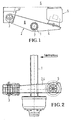
- Fig. 1
- eine schematische Seitenansicht einer die Erfindung aufweisenden Fahrzeugachsaufhängung im Bereich einer Seite einer (im Vertikalschnitt zu sehenden) Fahrzeugachse, wobei die Anordnung am gegenüberliegenden Ende des Achskörpers vorzugsweise entsprechend ausgebildet ist, und
- Fig. 2
- die Fahrzeugachsaufhängung von Fig. 1 im Bereich des einen Endes des Achskörpers in Draufsicht.
- Bei dem in den Fig. 1 und 2 dargestellten Ausführungsbeispiel der Erfindung weist die Fahrzeugachsaufhängung für einen starren rohrförmigen Achskörper je wenigstens einen Tragarm 2 beidseits der Fahrzeuglängsmittelebene auf. Der jeweilige Tragarm 2 ist mit seinem vorderen Ende an einem chassisfesten Lagerpunkt 3 angelenkt und im Abstand dahinter starr mit dem Achskörper 1 verbunden. Dargestellt ist eine Version, bei welcher der Achskörper 1 mit dem Tragarm 2 verschweißt ist, indem der Achskörper 1 in Öffnungen 7 von Seitenwangen 8 der Tragarme 2 aufgenommen ist. Der Achskörper 1 kann jedoch auch, z.B. mittels U-Bügel, an den Tragarmen 2 oder über Achslappen an Führungslenkern festgespannt sein. Ein von dem Achskörper 1 aus jeweils nach hinten ragender Tragarmabschnitt 4 bildet das untere Lager einer Luftfeder 5, auf deren Oberseite sich das Chassis 6 abstützt.
- Der Achskörper 1 wird von einem Achsrohr gebildet, dessen Wandstärke im Bereich der Verbindung mit dem Tragarm 2 vergrößert ist. In den dargestellten Fällen bildet die vergrößerte Wandstärke zusammenhängende Ringbereiche des Achskörpers 1.
- Eine vergrößerte Wandstärke des rohrförmigen Achskörpers 1 im Bereich der Verbindung mit dem Tragarm 2 ist in dem in Fig. 2 dargestellten Fall dadurch erreicht, daß der Achskörper 1 über seine gesamte Länge einen im wesentlichen gleichbleibenden Außendurchmesser aufweist, während der Innendurchmesser im Bereich der Verbindung mit dem Tragarm 2 zur Schaffung einer radial nach innen vorspringenden größeren Wandstärke führt.
-
- 1
- Achskörper
- 2
- Tragarm
- 3
- Lagerpunkt
- 4
- Tragarmabschnitt
- 5
- Luftfeder
- 6
- Chassis
- 7
- Öffnungen
- 8
- Seitenwangen
Claims (5)
- Aufhängung für eine einen starren rohrförmigen Achskörper (1) aufweisende Fahrzeugachse, mit wenigstens je einem Tragarm (2) beidseits der Fahrzeuglängsmittelebene, welcher mit seinem vorderen Ende an einem chassisfesten Lagerpunkt (3) angelenkt und im Abstand davon starr mit dem Achskörper (1) verbunden, z.B. verschweißt oder verspannt, ist, und mit Mitteln zum Verstärken des Achskörpers (1) im Bereich der Verbindung mit dem Tragarm (2), wobei ein von dem Achskörper (1) aus jeweils nach hinten ragender Tragarmabschnitt (4) das untere Lager einer Luftfeder (5) bildet, auf deren Oberseite sich das Chassis (6) abstützt, dadurch gekennzeichnet, daß als Achskörper (1) ein Achsrohr dient, dessen Wandstärke im Bereich der Verbindung mit dem Tragarm (2) oder von Führungslenkern vergrößert ist.
- Aufhängung nach Anspruch 1, dadurch gekennzeichnet, daß die vergrößerte Wandstärke unter jeder der Achseinspannungen wenigstens einen Ringbereich des Achskörpers (1) ausmacht.
- Aufhängung nach Anspruch 1 oder 2, dadurch gekennzeichnet, daß der Außendurchmesser des Achskörpers (1) über seine Länge im wesentlichen konstant ist.
- Aufhängung nach Anspruch 1 oder 2, dadurch gekennzeichnet, daß der Innendurchmesser des Achskörpers (1) über seine Länge im wesentlichen konstant ist.
- Aufhängung nach einem der vorhergehenden Ansprüche, dadurch gekennzeichnet, daß die Außen- bzw. Innendurchmesser der Bereiche vergrößerter Wandstärke größer als der Außendurchmesser und/oder kleiner als der Innendurchmesser des übrigen Achskörpers (1) sind/ist.
Applications Claiming Priority (2)
| Application Number | Priority Date | Filing Date | Title |
|---|---|---|---|
| DE19617929A DE19617929A1 (de) | 1996-05-06 | 1996-05-06 | Aufhängung für eine Fahrzeugachse |
| DE19617929 | 1996-05-06 |
Publications (3)
| Publication Number | Publication Date |
|---|---|
| EP0806311A2 true EP0806311A2 (de) | 1997-11-12 |
| EP0806311A3 EP0806311A3 (de) | 1999-05-19 |
| EP0806311B1 EP0806311B1 (de) | 2002-06-12 |
Family
ID=7793328
Family Applications (1)
| Application Number | Title | Priority Date | Filing Date |
|---|---|---|---|
| EP97104355A Revoked EP0806311B1 (de) | 1996-05-06 | 1997-03-14 | Aufhängung für eine Fahrzeugachse |
Country Status (3)
| Country | Link |
|---|---|
| EP (1) | EP0806311B1 (de) |
| AT (1) | ATE218988T1 (de) |
| DE (2) | DE19617929A1 (de) |
Cited By (3)
| Publication number | Priority date | Publication date | Assignee | Title |
|---|---|---|---|---|
| WO2002074563A1 (de) | 2001-03-21 | 2002-09-26 | Otto Sauer Achsenfabrik Keilberg | Achsaggregat |
| US6550869B2 (en) | 2001-03-21 | 2003-04-22 | Otto Sauer Achsenfabrik Keilberg | Vehicle axle assembly |
| EP2133164B2 (de) † | 2007-03-01 | 2017-08-23 | SAF-HOLLAND GmbH | Achskörper |
Families Citing this family (5)
| Publication number | Priority date | Publication date | Assignee | Title |
|---|---|---|---|---|
| DE29616257U1 (de) * | 1996-09-19 | 1996-11-07 | Otto Sauer Achsenfabrik Keilberg, 63856 Bessenbach | Aufhängung für luftgefederte Fahrzeugradachse |
| DE10060312C5 (de) * | 2000-07-06 | 2010-07-22 | Saf-Holland Gmbh | Fahrzeugachse |
| DE10055859B4 (de) * | 2000-11-10 | 2009-07-02 | Bpw Bergische Achsen Kg | Achskonstruktion für nichtangetriebene Fahrzeugachsen |
| NL1026947C2 (nl) * | 2004-09-01 | 2006-03-02 | Weweler Nv | Veerarm met geplet eindgedeelte. |
| DE102006037356B4 (de) * | 2006-08-09 | 2011-02-03 | Saf-Holland Gmbh | Achsaggregat |
Family Cites Families (3)
| Publication number | Priority date | Publication date | Assignee | Title |
|---|---|---|---|---|
| US1965267A (en) * | 1930-01-13 | 1934-07-03 | Urschel Engineering Company | Automobile axle |
| DE4232779C1 (de) * | 1992-09-30 | 1994-02-17 | Bergische Achsen Kotz Soehne | Achskörper und Achseinbindung |
| AU666572B2 (en) * | 1992-10-19 | 1996-02-15 | Hendrickson International Corporation | Axle suspension systems |
-
1996
- 1996-05-06 DE DE19617929A patent/DE19617929A1/de not_active Withdrawn
-
1997
- 1997-03-14 DE DE59707467T patent/DE59707467D1/de not_active Revoked
- 1997-03-14 AT AT97104355T patent/ATE218988T1/de not_active IP Right Cessation
- 1997-03-14 EP EP97104355A patent/EP0806311B1/de not_active Revoked
Cited By (7)
| Publication number | Priority date | Publication date | Assignee | Title |
|---|---|---|---|---|
| WO2002074563A1 (de) | 2001-03-21 | 2002-09-26 | Otto Sauer Achsenfabrik Keilberg | Achsaggregat |
| US6550869B2 (en) | 2001-03-21 | 2003-04-22 | Otto Sauer Achsenfabrik Keilberg | Vehicle axle assembly |
| DE10118523B4 (de) * | 2001-03-21 | 2006-09-07 | Otto Sauer Achsenfabrik Keilberg | Achsaggregat |
| CN100379589C (zh) * | 2001-03-21 | 2008-04-09 | 塞夫·霍兰德有限公司 | 轴总成 |
| DE10118523C5 (de) * | 2001-03-21 | 2009-06-25 | Saf-Holland Gmbh | Achsaggregat |
| EP2133164B2 (de) † | 2007-03-01 | 2017-08-23 | SAF-HOLLAND GmbH | Achskörper |
| EP2077921B2 (de) † | 2007-03-01 | 2018-01-24 | SAF-HOLLAND GmbH | Achskörper |
Also Published As
| Publication number | Publication date |
|---|---|
| EP0806311B1 (de) | 2002-06-12 |
| EP0806311A3 (de) | 1999-05-19 |
| DE19617929A1 (de) | 1997-12-11 |
| DE59707467D1 (de) | 2002-07-18 |
| ATE218988T1 (de) | 2002-06-15 |
Similar Documents
| Publication | Publication Date | Title |
|---|---|---|
| EP2049284B1 (de) | Achsaggregat | |
| DE102015015520B4 (de) | Drehstabfederungsstruktur | |
| EP1193087A2 (de) | Radaufhängung für Kraftfahrzeuge | |
| EP2881307A1 (de) | Hilfsrahmenanordnung für ein Fahrzeug | |
| EP3096963B1 (de) | Bauteilanbindung mit querkraftabstützender stützfläche | |
| EP0806311A2 (de) | Aufhängung für eine Fahrzeugachse | |
| DE19533479C2 (de) | Fahrzeugachse | |
| DE102014218159B4 (de) | Fahrwerksanordnung | |
| DE102013218028B4 (de) | Achsanbindung | |
| DE1951271B2 (de) | Einzelradaufhaengung fuer kraftfahrzeuge | |
| EP2492517A1 (de) | Verbindungsanordnung für Bambusrohre | |
| DE19642024A1 (de) | Rollbalg-Gasfeder mit einem Außenstützteil | |
| DE19631975B4 (de) | Kraftfahrzeugachse | |
| DE19638082C1 (de) | Aufhängung für eine Fahrzeugachse | |
| EP0800937B1 (de) | Achseinbindung | |
| DE20309455U1 (de) | Verbundlenkerachse für eine hintere Radaufhängung eines Kraftfahrzeugs | |
| EP1771310B1 (de) | Zylinderbaugruppe mit einem achsanschluss | |
| EP2711270A2 (de) | Rahmen für ein insbesondere landwirtschaftliches Nutzfahrzeug | |
| EP1907250B1 (de) | Stützwinde | |
| EP0600500B1 (de) | Anordnung einer Anhängerkupplung an einem Fahrzeug | |
| EP3882103A1 (de) | Kuppelstange insbesondere für ein schienenfahrzeug | |
| DE29624603U1 (de) | Aufhängung für eine Fahrzeugachse | |
| DE102008041501A1 (de) | Vorderbau für ein Fahrzeug | |
| DE102009041702A1 (de) | Lageranordnung zum Lagern eines Achsrohrs | |
| DE102004025283B3 (de) | Schwingungsdämpfer mit einem Verbindungsträger |
Legal Events
| Date | Code | Title | Description |
|---|---|---|---|
| PUAI | Public reference made under article 153(3) epc to a published international application that has entered the european phase |
Free format text: ORIGINAL CODE: 0009012 |
|
| AK | Designated contracting states |
Kind code of ref document: A2 Designated state(s): AT DE ES FR GB IT NL |
|
| PUAL | Search report despatched |
Free format text: ORIGINAL CODE: 0009013 |
|
| AK | Designated contracting states |
Kind code of ref document: A3 Designated state(s): AT DE ES FR GB IT NL |
|
| 17P | Request for examination filed |
Effective date: 19991113 |
|
| 17Q | First examination report despatched |
Effective date: 20010208 |
|
| GRAG | Despatch of communication of intention to grant |
Free format text: ORIGINAL CODE: EPIDOS AGRA |
|
| GRAG | Despatch of communication of intention to grant |
Free format text: ORIGINAL CODE: EPIDOS AGRA |
|
| GRAH | Despatch of communication of intention to grant a patent |
Free format text: ORIGINAL CODE: EPIDOS IGRA |
|
| GRAH | Despatch of communication of intention to grant a patent |
Free format text: ORIGINAL CODE: EPIDOS IGRA |
|
| GRAA | (expected) grant |
Free format text: ORIGINAL CODE: 0009210 |
|
| AK | Designated contracting states |
Kind code of ref document: B1 Designated state(s): AT DE ES FR GB IT NL |
|
| PG25 | Lapsed in a contracting state [announced via postgrant information from national office to epo] |
Ref country code: NL Free format text: LAPSE BECAUSE OF FAILURE TO SUBMIT A TRANSLATION OF THE DESCRIPTION OR TO PAY THE FEE WITHIN THE PRESCRIBED TIME-LIMIT Effective date: 20020612 Ref country code: IT Free format text: LAPSE BECAUSE OF FAILURE TO SUBMIT A TRANSLATION OF THE DESCRIPTION OR TO PAY THE FEE WITHIN THE PRESCRIBED TIME-LIMIT;WARNING: LAPSES OF ITALIAN PATENTS WITH EFFECTIVE DATE BEFORE 2007 MAY HAVE OCCURRED AT ANY TIME BEFORE 2007. THE CORRECT EFFECTIVE DATE MAY BE DIFFERENT FROM THE ONE RECORDED. Effective date: 20020612 Ref country code: GB Free format text: LAPSE BECAUSE OF FAILURE TO SUBMIT A TRANSLATION OF THE DESCRIPTION OR TO PAY THE FEE WITHIN THE PRESCRIBED TIME-LIMIT Effective date: 20020612 Ref country code: FR Free format text: LAPSE BECAUSE OF FAILURE TO SUBMIT A TRANSLATION OF THE DESCRIPTION OR TO PAY THE FEE WITHIN THE PRESCRIBED TIME-LIMIT Effective date: 20020612 |
|
| REF | Corresponds to: |
Ref document number: 218988 Country of ref document: AT Date of ref document: 20020615 Kind code of ref document: T |
|
| REG | Reference to a national code |
Ref country code: GB Ref legal event code: FG4D Free format text: NOT ENGLISH |
|
| REF | Corresponds to: |
Ref document number: 59707467 Country of ref document: DE Date of ref document: 20020718 |
|
| NLV1 | Nl: lapsed or annulled due to failure to fulfill the requirements of art. 29p and 29m of the patents act | ||
| GBV | Gb: ep patent (uk) treated as always having been void in accordance with gb section 77(7)/1977 [no translation filed] |
Effective date: 20020612 |
|
| PG25 | Lapsed in a contracting state [announced via postgrant information from national office to epo] |
Ref country code: ES Free format text: LAPSE BECAUSE OF FAILURE TO SUBMIT A TRANSLATION OF THE DESCRIPTION OR TO PAY THE FEE WITHIN THE PRESCRIBED TIME-LIMIT Effective date: 20021220 |
|
| EN | Fr: translation not filed | ||
| PLBQ | Unpublished change to opponent data |
Free format text: ORIGINAL CODE: EPIDOS OPPO |
|
| PLBI | Opposition filed |
Free format text: ORIGINAL CODE: 0009260 |
|
| PLBF | Reply of patent proprietor to notice(s) of opposition |
Free format text: ORIGINAL CODE: EPIDOS OBSO |
|
| 26 | Opposition filed |
Opponent name: BPW BERGISCHE ACHSEN KG Effective date: 20030306 |
|
| PLAX | Notice of opposition and request to file observation + time limit sent |
Free format text: ORIGINAL CODE: EPIDOSNOBS2 |
|
| PLBB | Reply of patent proprietor to notice(s) of opposition received |
Free format text: ORIGINAL CODE: EPIDOSNOBS3 |
|
| PGFP | Annual fee paid to national office [announced via postgrant information from national office to epo] |
Ref country code: AT Payment date: 20040322 Year of fee payment: 8 |
|
| PGFP | Annual fee paid to national office [announced via postgrant information from national office to epo] |
Ref country code: DE Payment date: 20040527 Year of fee payment: 8 |
|
| RDAF | Communication despatched that patent is revoked |
Free format text: ORIGINAL CODE: EPIDOSNREV1 |
|
| RDAG | Patent revoked |
Free format text: ORIGINAL CODE: 0009271 |
|
| STAA | Information on the status of an ep patent application or granted ep patent |
Free format text: STATUS: PATENT REVOKED |
|
| 27W | Patent revoked |
Effective date: 20040617 |