EP0805895B1 - Materiau de montage stratifie, procede et flanc pour la fabrication dudit materiau - Google Patents
Materiau de montage stratifie, procede et flanc pour la fabrication dudit materiau Download PDFInfo
- Publication number
- EP0805895B1 EP0805895B1 EP96941259A EP96941259A EP0805895B1 EP 0805895 B1 EP0805895 B1 EP 0805895B1 EP 96941259 A EP96941259 A EP 96941259A EP 96941259 A EP96941259 A EP 96941259A EP 0805895 B1 EP0805895 B1 EP 0805895B1
- Authority
- EP
- European Patent Office
- Prior art keywords
- band
- clothing
- thread
- seam
- laminated
- Prior art date
- Legal status (The legal status is an assumption and is not a legal conclusion. Google has not performed a legal analysis and makes no representation as to the accuracy of the status listed.)
- Expired - Lifetime
Links
Images


Classifications
-
- D—TEXTILES; PAPER
- D21—PAPER-MAKING; PRODUCTION OF CELLULOSE
- D21F—PAPER-MAKING MACHINES; METHODS OF PRODUCING PAPER THEREON
- D21F1/00—Wet end of machines for making continuous webs of paper
- D21F1/0027—Screen-cloths
- D21F1/0054—Seams thereof
-
- D—TEXTILES; PAPER
- D21—PAPER-MAKING; PRODUCTION OF CELLULOSE
- D21F—PAPER-MAKING MACHINES; METHODS OF PRODUCING PAPER THEREON
- D21F7/00—Other details of machines for making continuous webs of paper
- D21F7/08—Felts
- D21F7/10—Seams thereof
-
- Y—GENERAL TAGGING OF NEW TECHNOLOGICAL DEVELOPMENTS; GENERAL TAGGING OF CROSS-SECTIONAL TECHNOLOGIES SPANNING OVER SEVERAL SECTIONS OF THE IPC; TECHNICAL SUBJECTS COVERED BY FORMER USPC CROSS-REFERENCE ART COLLECTIONS [XRACs] AND DIGESTS
- Y10—TECHNICAL SUBJECTS COVERED BY FORMER USPC
- Y10T—TECHNICAL SUBJECTS COVERED BY FORMER US CLASSIFICATION
- Y10T428/00—Stock material or miscellaneous articles
- Y10T428/24—Structurally defined web or sheet [e.g., overall dimension, etc.]
- Y10T428/2419—Fold at edge
- Y10T428/24264—Particular fold structure [e.g., beveled, etc.]
-
- Y—GENERAL TAGGING OF NEW TECHNOLOGICAL DEVELOPMENTS; GENERAL TAGGING OF CROSS-SECTIONAL TECHNOLOGIES SPANNING OVER SEVERAL SECTIONS OF THE IPC; TECHNICAL SUBJECTS COVERED BY FORMER USPC CROSS-REFERENCE ART COLLECTIONS [XRACs] AND DIGESTS
- Y10—TECHNICAL SUBJECTS COVERED BY FORMER USPC
- Y10T—TECHNICAL SUBJECTS COVERED BY FORMER US CLASSIFICATION
- Y10T428/00—Stock material or miscellaneous articles
- Y10T428/24—Structurally defined web or sheet [e.g., overall dimension, etc.]
- Y10T428/24777—Edge feature
- Y10T428/24785—Edge feature including layer embodying mechanically interengaged strands, strand portions or strand-like strips [e.g., weave, knit, etc.]
Definitions
- the present invention generally relates to a laminated clothing, such as a laminated press felt, for use in a papermaking or cellulose manufacturing machine. More specifically, the invention relates to a clothing having in its thickness direction a first and, laminated therewith, a second layer, each having a direction-defined thread system, said thread systems making an angle with the machine direction of the clothing and with one another. The invention also relates to a method and a blank for manufacturing such a laminated clothing.
- SE 468,602 discloses a laminated press felt of the above-mentioned type, and a method of manufacturing the same.
- a modern press felt comprises a soft compressible part adjacent to the paper web for protection, and a relatively incompressible part, called base fabric, for receiving and removing water pressed out in the press nips.
- the compressible part usually is a single- or double-face fibre layer needled to the base fabric.
- the base fabric usually consists of woven monofilaments, but also spun threads or twisted multifilaments are used.
- polyamide is an impact-resistant fibre that does not fibrillate owing to repeated compressions in a press nip.
- laminated press felts which are a special type of multilayer press felts and which have implied a great step forward
- two base fabrics are included, which have separate thread systems and which are combined, i.e. laminated, while manufacturing the felt.
- Laminated press felts are particularly used in highly loaded press positions where large amounts of water are to be processed, in many cases requiring low marking. By different combinations of top and bottom fabrics it has been possible to adapt the structure to demanding machine positions.
- a new type of laminated press felt was introduced, marketed under the designation DYNATEXTM supplied by Albany International Corp., at least one of the two base fabrics, i.e. one of the two layers laminated with each other, consisting of a spirally rolled strip, preferably a flat-woven strip.
- This spirally rolled base fabric is the subject matter of SE 468,602 mentioned by way of introduction.
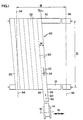
- the principle is illustrated in Fig. 1 on the accompanying sheet of drawing, which illustrates schematically and from above a method of manufacturing such a spirally rolled base fabric.
- Two rotatably mounted rollers 10, 12 having parallel axes are arranged at a mutual axial distance D.
- a supply coil 14 is rotatably arranged about an axis 16 and movable in parallel with the shafts 10 and 12, as indicated by arrow 18.
- the supply coil 14 accommodates a rolled-up supply of a flat-woven strip 20 of fabric made from yarn, having a width w between its longitudinal edges 26 and 28.
- the strip 20 is composed of two mutually perpendicular thread systems consisting of longitudinal threads (warp threads) and transverse threads (weft threads), respectively, schematically shown at 22 and 24, respectively.
- the strip 20 is discharged in the direction of arrow 30 to be spirally rolled about the shafts 10, 12 into an endless product, below called “endless band", generally designated 40.
- the final width of the band 40 is designated B and is defined by lines 34 and 36 along which the sides of the band 40 are cut after the spiral rolling.
- the strip 20 is applied at an angle ⁇ to the machine direction which is designated MD and which is the running direction of the finished press felt in the machine.
- the longitudinal edges 26, 28 of the strip 20 can be made to be positioned edge by edge or in overlapping fashion, preferably joined together.
- the completed, laminated press felt has a width B which is determined by the number of spiral turns, and a length equalling approximately twice the axial distance D and thus easily being possible to vary by changing D.
- the advantages of this prior-art spiral rolling is disclosed in SE 468,602 and will not be repeated here.
- a special advantage has been obtained with a multiaxial variant of DYNATEXTM, where two spirally rolled endless base fabric bands as described above are laminated in such a manner that the spiral turns of one band intersects the spiral turns of the other band. It is possible to manufacture such a multiaxial, laminated base fabric by spirally rolling a first base fabric band according to Fig. 1, and spirally rolling a second base fabric band of essentially the same length, but of opposite pitch angle (i.e. the strip in the second base fabric band is directed obliquely upwards to the right instead of obliquely upwards to the left as in Fig. 1).
- a laminated base fabric which, seen from above, has on the one hand two systems of longitudinal threads 22 making an angle with each other and with the machine direction MD and, on the other hand, two systems of transverse threads 24 making an angle with each other as well as with the longitudinal threads 22 and the machine direction MD, i.e. totally four thread directions.
- the multiaxial, laminated base fabric can then be provided with a needled batt layer, which produces a joining effect on the two layers.
- the resultant product is called a multiaxial, laminated press felt.
- Runs with multiaxial laminated press felts have conferred a number of advantages, mainly an improved stability as to shape under pressure thanks to the crossing of the thread systems preventing them from sliding into each other, i.e. improved incompressibility.
- a further advantage is that the life of the press felt increases since it will keep more open for a longer time and, thus, its properties change less in time.
- a problem of the multiaxial laminated press felt, however, is that the manufacture thereof in respect of lamination is relatively complicated and time-consuming.
- a further problem of the multiaxial laminated press felt is that it has no openable seam, and therefore cannot be installed and run in machine positions requiring a seamed felt.
- the invention suggests a laminated clothing and a method for manufacturing a laminated clothing having the features defined in claims 1 and 7, respectively.
- a blank intended for the manufacture of a laminated clothing is provided according to the claim 14.
- clothing means either a finished product for installation, for instance a press felt comprising a laminated base fabric and, needled thereto, a batt, or part of a finished product, for instance merely a laminated base fabric for a press felt.
- the term “clothing” should further not be considered limited to the field of press felts.
- Other possible fields of application for the invention are LNP bands (long nip presses), transfer bands, clothings for forming or drying, etc.
- a laminated clothing for a papermaking or cellulose manufacturing machine having in its thickness direction a first and, laminated therewith, a second layer, each having an inclined direction-defined thread system, said thread systems being inclined relative to the machine direction of the clothing and relative to one another.
- first and the second layer constitute an outer and an inner part, respectively, of an endless band which is so flattened that two edge folds are formed transversely of the machine direction, and which is then doubled with the edge folds coupled to each other, said band having a direction-defined thread system which is inclined relative to the machine direction and which, owing to said flattening and doubling of the band, forms the thread systems, inclined relative to each other, of the first and the second layer.
- a technical effect that is essential to and characteristic of the invention is that the crossing of the thread systems which are included in the laminated layers and which in the finished product make an angle with each other as well as with the machine direction, is effected fully automatically by the flattening and doubling of one and the same endless band. If the inclined, direction-defined thread systems of the endless band make an angle of, for instance, + ⁇ with the machine direction MD, the flattened and doubled band will have, as seen perpendicular to its major face, two thread systems which make an angle 2 ⁇ with each other and which make an angle + ⁇ and - ⁇ , respectively, with the machine direction MD.
- a multiaxial laminated clothing of the above design is easier to manufacture since the entire clothing keeps together, compared with the known technique of manufacturing the laminated clothing from two initially separate bands. No adaptation in respect of dimensions of two separate bands is required. Moreover, the time of manufacture is reduced since merely one endless band has to be manufactured. A further advantage is that the product properties, such as tendency to shrinkage and angles of the thread system, will be uniform in the laminated layers.
- the endless band can be manufactured in any fashion whatever, provided that it comprises at least one inclined, direction-defined thread system which makes an angle with the longitudinal direction of the band.
- the endless band may also be a warp knit.
- endless band also comprises bands having one or more openable seams in their transverse direction, even if such a design probably is less preferable.
- the endless band is formed of a spirally rolled strip, which has a width smaller than the width of the band and which has a direction-defined thread system extended in the longitudinal direction of the strip and forming the inclined, direction-defined thread system of the endless band.
- the axial distance D must be doubled, i.e. 20 m, for forming an about 40-m-long endless band.
- This increased axial distance implies that the width of the strip must be substantially doubled if the pitch angle is to remain equal to ⁇ .
- Starting from and spirally rolling a wider strip contributes in an advantageous manner to a shorter time of manufacture, on the one hand in respect of the time required for manufacturing the actual strip and, on the other hand, regarding the time required for spirally rolling and joining the spiral turns.
- a further advantage of the design having a spirally rolled strip is that it is possible to better check the angle of the threads in the two laminated layers.
- the inventive principle of providing the multiaxial configuration from one and the same endless band by flattening and doubling the same also makes it possible to provide the clothing with an openable seam adjacent to the coupled-together edge folds. Even if designs of the invention having an openable seam are preferred, the field of definition of the claims should, however, also be considered to comprise clothings without an openable seam for the probably less interesting case of permanently coupled-together edge folds.
- the edge folds of the band are openably joined by means of two rows of seam loops, said rows forming together with a pintle wire an openable seam of the clothing.
- Openable seams with seam loops and pintle wires are per se previously known, but arranging rows of seam loops in a structure having inclined thread systems, i.e. thread systems making an angle with MD as well as CD, is something completely new, especially in a laminated structure.
- Modern techniques for manufacturing seam loops in a fabric are all dependent on the fact that the fabric has an MD thread system which can either on its own form the seam loops or hold seam spirals inserted in the CD direction.
- SE 429,982 An example of a prior-art loop seam of a press felt having MD thread systems is disclosed in SE 429,982, which relates to a non-laminated press felt comprising a base fabric having two layers of MD threads, which form seam loops in the transition between the layers.
- FI 77072, EP-B1-0 425 523 and US-A-5,015,220 disclose clothings, in which an endless band having perpendicular thread systems has been flattened and doubled, the two edge folds being openably joined by means of seam loops formed of MD threads.
- MD threads are an absolute condition for the possibility of forming seam loops.
- the seam loops are formed of the MD threads as these turn in the edge folds.
- a drawback of the prior-art techniques for manufacturing seam loops is that they cause an undesired change of the structure and properties of the material along the rows of seam loops owing to the ravelling of CD threads.
- a new technique which permits manufacture of seam loops in a clothing having inclined thread systems, especially in a laminated clothing having inclined, intersecting thread systems.
- the seam loops are manufactured from a separate filament, below called seam loop thread, which is formed, by means of a special loop-forming device, into loops in the band.
- the structure of the endless band is neither damaged nor influenced, and the technique does not require the existence of MD threads in the band material.
- the loop-forming device and the band are caused to move relative to each other along the intended seam line, i.e. perpendicular to the longitudinal edges of the band, before carrying out the final doubling.
- the seam loop thread is pulled in double state through the band in the thickness direction thereof in each point that is to be provided with a seam loop.
- This operation is carried out with a thread guide entering and leaving the band through the same hole, preferably perpendicular to the surface thereof, i.e. perpendicular to the intended edge fold.
- the thus formed thread loop is kept on the opposite side and formed round a forming member or the like, the seam loop thread obtaining its desired loop shape round the forming member by being tensioned against the forming member, preferably during the forming of the subsequent thread loop.
- An advantage of this technique of applying seam loops is that it can be carried out on all types of flat, textile structures that are to be folded along a seam edge, since the technique does not require the existence of any MD thread systems perpendicular to the seam line, or CD thread systems in parallel with the seam line.
- a technique is suggested that permits the manufacture of seam loops in a clothing having inclined thread systems, especially in a laminated clothing having inclined intersecting thread systems.
- the seam loops are made from a preformed spiral.
- US-A-4,896,702 discloses the arranging, in the edge folds of a flattened, doubled band, of preformed seam spirals for forming rows of seam loops along the edge folds.
- the spirals must be inserted in the CD direction and to make this possible, the structure must first be opened along the edge folds by removing special CD filler elements and, optionally, CD threads in the fabric.
- This known technique therefore cannot be used in a multiaxial laminated clothing having inclined thread systems since there are no MD threads to be ravelled adjacent to the edge folds of a multiaxial laminated construction.
- seam loops are manufactured from a preformed spiral, which instead is pulled or pressed through the band transversely of the major plane thereof, preferably substantially perpendicular to the intended edge fold.
- loop side one side forming seam loops
- mounting side one side for anchoring in the band
- the loop side of the spiral thus is passed through the band from the rear side to the front side of the band.
- a pintle wire or the like can afterwards be passed through the loops to prevent them from falling back to the rear side.
- the mounting side of the spiral is passed through the band from the front side to the rear side of the band.
- a pintle wire or the like can be passed through the spiral on the rear side of the band to prevent the spiral from falling out on the front side.
- a clothing according to claim 14 which comprises, in contrast to the above-described embodiment, two or more endless belts connected in series.
- the basic principle is the same, but the manufacture of longer clothings is simplified by the technique of connecting in series.
- the modifications and methods of manufacture as described above for the first embodiment can be used also for the variant connected in series according to claim 14.
- the endless structure formed of bands connected in series can be openable adjacent to one or more of the coupled-together edge folds, or as an alternative have only permanently coupled-together edge folds.
- a method for manufacturing an embodiment of a clothing according to the invention here a laminated base fabric for a press felt, will now be described with reference to the accompanying drawings.
- an endless band is made from a strip, which is spirally rolled in the same manner as already described above in connection with Fig. 1. Therefore, the description of the spiral rolling technique will not be repeated, since it is known to those skilled in the art from SE 468,602.
- the strip 20 is of a width w which is smaller than the width B of the finished base fabric, and in the embodiment illustrated, the strip 20 is flat-woven with longitudinal and transverse thread systems 22, 24, respectively.
- the axial distance D should be doubled compared with the case in SE 468,602, such that the resultant endless band 40 obtains a circumferential length which is approximately twice the circumferential length of the finished press felt.
- the endless band is not composed of a strip, but instead consists of a uniform structure.
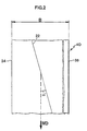
- the endless band is provided with two rows of seam loops 42, 44 along seam lines L1 and L2 coinciding with intended edge folds of the band (see Fig. 4).
- the seam lines L1 and L2 can be marked in advance on the band 40, as indicated in Fig. 5 by a full and a dashed line, respectively.
- the seam lines L1 and L2 are inclined relative to the spiral turns of the strip, i.e. inclined in relation to the longitudinal threads 22 as well as the transverse threads 24.
- the seam loops 42, 44 are made from a seam loop thread 46 which is separate from the band, preferably monofilament polyamide, in a manner that will be described in more detail below.
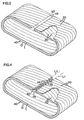
- the endless band is flattened such that the seam lines L1 and L2 coincide with two formed edge folds 48, 50. Then the endless band is doubled to the appearance shown in Fig. 4, where the edge folds 48 and 50 with the loop rows 42, 44 are arranged opposite each other.
- a laminated structure is obtained, having an outer layer O and an inner layer I.
- the laminated base fabric 40 therefore has, perpendicularly to its major face, four non-coinciding thread directions which are all inclined relative to the machine direction MD, viz. longitudinal and transverse threads 22, 24 in the inner layer I and longitudinal and transverse threads 22, 24 in the outer layer O.
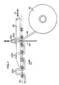
- the loop-forming device 52 comprises an upper and a lower part which are caused to move synchronously with each other and intermittently relative to the stationary band 40 above and below, respectively, the seam line L1 in the direction indicated by arrow 54.
- the lower part of the loop-forming device 52 comprises a supporting plate 56 abutting against the underside of the band 40, a rotating feeding roller 58 which, under the action of drive means (not shown), causes the intermittent movement, and a thread guide 60 making a reciprocating movement perpendicular to the plate 56 under the action of a drive means (not shown), such as a piston-and-cylinder assembly.
- a drive means such as a piston-and-cylinder assembly.
- Fig. 6 schematically illustrates a supply coil 62 storing seam loop thread 46 which, via a roller 64, is fed through an upper eye 66 (see Fig. 7) of the thread guide 60.
- the upper part of the loop-forming device 52 comprises an elongate loop-forming member 68 which can be made to perform a reciprocating motion in its longitudinal direction, as marked by a double arrow 72, by means of a piston-and-cylinder assembly 70 mounted on an upper plate 74.
- the member 68 has, in the embodiment shown, a cross-section conforming with the desired shape of the seam loops 42 and 44 and is extended along a line which is parallel with and slightly offset relative to the seam line L1.
- the member 68 is prevented from hitting the thread guide 60, which moves up and down through the band 40 in the actual seam line L1.
- the plate 74 and the member 68 mounted thereon are made, by drive means (not shown), to move in combination with the lower part of the loop-forming device 52 in the direction of arrow 54.
- the mode of operation of the loop-forming device 52 is more clearly seen from Fig. 7, where the major plane of the endless band is marked with 40, and the band is made of fourfold yarn.
- Two seam loops 42a and 42b have already been manufactured to the left of the thread guide 60, and a new seam loop 42c is being manufactured.
- the device 52 performs the following operations.
- a first step the thread 46 is raised by means of the thread guide 60 upwards through a hole in the band 40.
- the member 68 is inserted in the already formed seam loops 42a, 42b and the loop-forming device 52 is kept stationary relative to the band 40.
- the new loop 42c is not yet positioned on the member 68. Thanks to the member 68 being inserted in the preceding loop 42b, the latter is tensioned round the member 68 during this first step.
- the thread guide 60 moves downwards, the thread 46 sliding on through the eye 66, such that the new loop 42c is formed of the amount of thread that is now positioned on the upper side of the band 40.
- This new loop 42c can in some suitable manner, for instance by guide rails or the like acting on the outsides of the loop, be moved to such a position that in a subsequent step the member 68 can be inserted through the loop 42c.
- An example of such guiding of the loops will be described with reference to the embodiment shown in Figs 8-10.
- a fourth step the member 68 moves to the left, to the situation shown in Fig. 7, for catching on the one hand the new loop 42c and, on the other hand, a suitable number of the previously formed loops 42b, 42a, etc.
- the thread guide 60 moves to its lower turning position under the band 40.
- an indexing in the direction of arrow 54 of the loop-forming device 52 is carried out to the next position along the seam line L1.
- the main purpose of the member 68 is to keep back a sufficient amount of thread 46 such that the correct size of the seam loops 42 is formed. If a member 68 of a certain shape is used, it may also, like in this case, be used to form and set the loops 42. The member 68 can be heated for setting. However, it is also possible to set the loops 42 in a separate subsequent process, in which the loops 42 can remain on the member 68, or a new special insert thread (not shown) can be inserted in these to give them the desired shape.
- the seam loop thread 46 can be a monofilament yarn of a suitable dimension, for instance 0.35-0.50 mm, doubled monofilament yarn, multifilament yarn etc.
- the loops 42, 44 can be formed to a diameter of 1.7 mm and be coupled to an insert thread of 1.5 mm. The thermal treatment can then be carried out, if this has not already.been done during the forming operation.
- the insert thread can then be changed for a thinner thread of for instance 0.7 mm, whereupon the laminated base fabric 40 is provided with a batt layer (not shown) by needling through both layers O and I.
- Figs 8-11 illustrate an alternative embodiment for carrying out the manufacture of loops.
- the construction and function of the loop-forming device 52 is essentially the same as described above for the embodiment in Figs 5-7, and like components are provided with the same reference numerals.
- the difference between this and the previously described embodiment is above all that the device 52 in Figs 8-11 is stationary, and that the endless band 40 is instead made to move relative to the device 52 in the direction of the seam line L1/L2 as indicated by arrow 54 in Figs 8-11.
- the loop-forming device 52 is mounted on a stationary frame 80, which is arranged approximately in the centre of a horizontal beam 82, which is supported by legs 84 and one end of which is openable at 86, such that the endless band 40 can be slipped over and made to rest on the beam 82.
- the beam 82 is approximately twice as long as the width B of the band 40.
- the loop-forming device 52 is of essentially the same composition as the device in Fig. 6.
- Fig. 9 also shows a piston-and-cylinder assembly 88 for driving the thread guide 60 as well as a further feeding roller 58 for the intermittent feeding of the band 40.
- Figs 10 and 11 illustrate schematically how the loops 42 are guided in the lateral direction during the manufacture of loops, thereby making it possible to catch them and form them round the reciprocating member 68.
- a horizontally extended, platform-type guide 90 is fixedly mounted on the frame 80 and comprises along its long side facing the member 68 and the loops 42 a first guiding wall 92 and a second guiding wall 94, which are interconnected as shown in Fig. 10 and which are interconnected via an inclined partition 96.
- the loop 42" which is presently being formed by the thread guide 60 is positioned adjacent to the first guiding wall 92 immediately adjacent to the inclined partition 96.
- the loop will, under the action of the inclined partition 96, be guided aside, away from the seam line L1 to a laterally offset position which coincides with the path of movement of the member 68.
- An optional number of loops, designated 42' in Fig. 10 are held in this laterally offset position by the second guiding wall 94.
- Fig. 10 also shows an abutment 98 which prevents the newly formed loop 42" from turning forwards to such an extent that the member 68 misses the loop.
- Figs 12-14 illustrate a different method for manufacturing the seam loops 42, 44.
- this method use is made, adjacent to each edge fold 48, 50, of a spiral 100 known to those skilled in the art and made of, for instance, polyamide.
- the band 40 may, for instance, but not necessarily, be a woven structure, the stitches being used for the mounting of the spiral 100.
- Each needle 102 For mounting a spiral 100, use is made of a set of needles 102, each essentially having the form of a crochet needle with a "hook" 104 at one end. Each needle 102 also comprises a pivotable locking arm 106, whose function will be described below.
- the needles 102 are first pressed through the band 40, for instance, from the rear side of the band 40 towards its front side.
- the articulated locking arms 106 are parallel with the needle 102 and directed downwards to be able to pass through the band 40.
- the needles 102 are pressed through so far that the free ends of the locking arms 106 can be made to rest against the band on the exit side of the needles, as shown in Fig. 12.
- the hooks 104 of the needles 102 are then attached in the spiral loops, on the loop side or mounting side of the spiral 100, as mentioned above, whereupon a pintle rod or wire 108 is passed through the spiral 100 to prevent the spiral 100 from releasing the hooks 104.
- each locking arm 106 being moved, under the action of the band 40, to a locked position, according to Fig. 13, where the locking arm together with the associated hook 104 forms a closed eye of the needle, in which the spiral loop is caught.
- the pintle rod or wire 108 can now be removed (alternatively replaced by a thinner one), whereupon the needles 100 can be pulled back the last distance down through the band 40, as illustrated in Fig. 14.
- the spiral 100 is mounted in the correct position in the band 40 and can be fixed in some suitable manner, for instance by inserting a pintle wire in the CD direction through the spiral on the rear side of the band 40.
- the seem loops or alternatively the spirals could be mounted on the band before making this endless, if the band is manufactured in some other manner than described above.
Landscapes
- Paper (AREA)
- Laminated Bodies (AREA)
- Nonwoven Fabrics (AREA)
- Reinforced Plastic Materials (AREA)
- Manufacturing Of Multi-Layer Textile Fabrics (AREA)
- Treatment Of Fiber Materials (AREA)
- Yarns And Mechanical Finishing Of Yarns Or Ropes (AREA)
- Treatments For Attaching Organic Compounds To Fibrous Goods (AREA)
Claims (16)
- Habillage stratifié pour une machine à papier ou à cellulose, ledit habillage ayant dans le sens de son épaisseur une première couche (O) et, stratifiée avec, une deuxième couche (I), chacune ayant un système de fil incliné à direction définie (22; 22), lesdits systèmes de fil (22 ; 22) étant inclinés par rapport à la direction machine (MD) de l'habillage et l'un par rapport à l'autre, caractérisé en ce que les première et deuxième couches (O, I) constituent une partie extérieure et une partie intérieure respectivement d'une bande sans fin (40) qui est aplatie de telle sorte que deux plis de bord (48, 50) sont formés transversalement à la direction de la machine (MD), et qui est alors doublée avec les plis de bord (48, 50) reliés l'un à l'autre, ladite bande ayant un système de fil à direction définie (22) qui est incliné par rapport à la direction de la machine (MD) et qui, du fait dudit aplatissement et dudit doublage de la bande, forme les systèmes de fil (22; 22), inclinés l'un par rapport à l'autre, des première et deuxième couches (O, I).
- Habillage selon la revendication 1, dans lequel la bande (40) est formée avec une bande enroulée en spirale (20), qui a une largeur (w) inférieure à la largeur (B) de la bande (40) et qui a un système de fil à direction définie (22) qui s'étend dans la direction longitudinale de la bande (20) et qui forme les systèmes de fil inclinés à direction définie (22) de la bande (40).
- Habillage selon l'une quelconque des revendications précédentes, dans lequel la bande (40) est fabriquée dans une toile fabriquée à partir de fil.
- Habillage selon la revendication 3, dans lequel la bande (40) est tissée.
- Habillage selon l'une quelconque des revendications précédentes, dans lequel les plis de bord reliés ensemble (48, 50) de la bande (40) sont reliés ensemble au moyen de deux rangées de boucles de couture (42, 44), qui sont prévues pour former, avec un fil de pivot, une couture pouvant être ouverte de l'habillage.
- Habillage selon la revendication 5, dans lequel chaque rangée de boucles de couture (42, 44) est formée avec un fil (46) séparé de la matière de bande.
- Habillage selon la revendication 5, dans lequel chaque rangée de boucles de couture (42, 44) est formée à partir d'une spirale préformée (100) séparée de la matière de bande.
- Procédé de fabrication d'un habillage stratifié pour une machine à papier ou à cellulose, ledit habillage ayant dans le sens de son épaisseur une première couche (O) et, stratifiée avec celle-ci, une deuxième couche (I), chacune ayant un système de fil incliné à direction définie (22; 22), lesdits systèmes de fil (22; 22) étant inclinés par rapport à la direction de la machine (MD) de l'habillage et l'un par rapport à l'autre, caractérisé par les étapes suivantes :a) fabrication d'une bande sans fin (40), qui est d'une circonférence qui est approximativement le double de la longueur de la circonférence de l'habillage fini et qui a un système de fil incliné à direction définie (22) qui fait un angle avec la direction longitudinale (MD) de la bande (40),b) aplatissement de la bande (40), en formant ainsi deux plis de bord (48, 50), etc) doublage de la bande aplatie (40) en raccordant et en reliant ensemble les deux plis de bord (48, 50), de telle sorte que la moitié extérieure et la moitié intérieure de la bande doublée (40) forment la première couche (O) et la deuxième couche (I), respectivement, et de telle sorte que lesdits systèmes de fil à direction définie (22; 22) de la première et de la deuxième couche forment tous deux une partie dudit système de fil incliné à direction définie de la bande (40).
- Procédé selon la revendication 8, dans lequel l'étape de fabrication de la bande sans fin (40) comporte les étapes partielles suivantes :a1) fabrication d'une bande (20) qui est d'une largeur (w) inférieure à la largeur de l'habillage et qui a un système de fil à direction définie (22) qui s'étend dans sa direction longitudinale, eta2) enroulement en spirale de la bande (20) afin de former la bande sans fin (40), le système de fil incliné à direction définie (22) de la bande (40) se composant dudit système de fil (22) de la bande (20).
- Procédé selon la revendication 9, dans lequel l'étape partielle de fabrication de la bande (20) comprend la mesure de tissage à plat de celle-ci.
- Procédé selon l'une quelconque des revendications 8 à 10, dans lequel l'étape de liaison ensemble des plis de bord (48, 50) de la bande comprend l'étape de liaison de ceux-ci ensemble au moyen d'une couture à boucle pouvant être ouverte, qui comprend deux rangées de boucles de couture (42, 44), chaque rangée étant étendue le long de son pli de bord associé (48, 50).
- Procédé selon l'une quelconque des revendications 8 à 10, dans lequel les boucles de couture (42, 44) sont constituées par un fil séparé (46) qui est introduit de manière successive dans la bande (40) le long de la ligne de couture prévue (L1, L2).
- Procédé selon l'une quelconque des revendications 8 à 10, dans lequel les boucles de couture (42, 44) sont constituées par une spirale préformée séparée (100), dont un côté est passé à travers la bande (40) transversalement au plan principal de celle-ci.
- Habillage stratifié pour une machine à papier ou à cellulose, ledit habillage ayant dans le sens de son épaisseur une première couche (O) et, stratifiée avec celle-ci, une deuxième couche (I), ayant chacune un système de fil incliné à direction définie (22; 22), lesdits systèmes de fil (22; 22) étant inclinés par rapport à la direction machine (MD) de l'habillage et l'un par rapport à l'autre, caractérisé en ce que l'habillage comprend deux ou plusieurs bandes sans fin, chacune étant aplatie de telle sorte que deux plis de bord sont formés transversalement à la direction de la machine (MD), lesdites bandes aplaties étant, en reliant ensemble les plis de bord, reliées de manière successive en série dans le sens de la machine afin de former une structure sans fin, lesdites première et deuxième couches (O, I) étant une partie extérieure et intérieure, respectivement, de la structure sans fin, lesdites bandes ayant un système de fil à direction définie (22) qui est incliné par rapport à la direction de la machine (MD) et qui, du fait dudit aplatissement, forment les systèmes de fil (22, 22) inclinés l'un par rapport à l'autre des première et deuxième couches (O, I).
- Ebauche pour la fabrication d'un habillage stratifié pour une machine à papier ou à cellulose, ledit habillage ayant dans le sens de son épaisseur une première couche (O) et, stratifiée avec celle-ci, une deuxième couche (I), chacune ayant un système de fil incliné à direction définie (22; 22), lesdits systèmes de fil étant inclinés par rapport à la direction machine (MD) de l'habillage et l'un par rapport à l'autre, caractérisée en ce que l'ébauche comprend une bande sans fin (40) qui a un système de fil à direction définie (22) incliné par rapport à la direction de la machine (MD) et qui est aplatie de telle sorte que deux plis de bord (48, 50) sont formés transversalement à la direction longitudinale de la bande, le système de fil incliné à direction définie (22) de la bande (40) formant, du fait de l'aplatissement de la bande, les systèmes de fil (22; 22), inclinés l'un par rapport à l'autre, de la première et la deuxième couche (O, I), ladite bande aplatie étant prévue pour être doublée avec plis de bord (48, 50) dans l'état reliés ensemble, en formant ainsi ledit habillage stratifiée.
- Ebauche selon la revendication 15, dans lequel les plis de bord (48, 50) de la bande (40) ont chacun une rangée de boucles de couture (42, 44), lesdites rangées étant prévues pour former, avec un fil de pivot, une couture pouvant être ouverte de l'habillage.
Applications Claiming Priority (3)
| Application Number | Priority Date | Filing Date | Title |
|---|---|---|---|
| SE9504275A SE505390C2 (sv) | 1995-11-30 | 1995-11-30 | Laminerad beklädnad samt metod och ämne för framställning därav |
| SE9504275 | 1995-11-30 | ||
| PCT/SE1996/001536 WO1997020105A1 (fr) | 1995-11-30 | 1996-11-26 | Materiau de montage stratifie, procede et flanc pour la fabrication dudit materiau |
Publications (2)
| Publication Number | Publication Date |
|---|---|
| EP0805895A1 EP0805895A1 (fr) | 1997-11-12 |
| EP0805895B1 true EP0805895B1 (fr) | 2001-10-24 |
Family
ID=20400413
Family Applications (1)
| Application Number | Title | Priority Date | Filing Date |
|---|---|---|---|
| EP96941259A Expired - Lifetime EP0805895B1 (fr) | 1995-11-30 | 1996-11-26 | Materiau de montage stratifie, procede et flanc pour la fabrication dudit materiau |
Country Status (18)
| Country | Link |
|---|---|
| US (1) | US6265048B1 (fr) |
| EP (1) | EP0805895B1 (fr) |
| JP (1) | JP4128218B2 (fr) |
| KR (1) | KR100479565B1 (fr) |
| CN (1) | CN1077937C (fr) |
| AT (1) | ATE207558T1 (fr) |
| AU (1) | AU703689B2 (fr) |
| BR (1) | BR9607080A (fr) |
| CA (1) | CA2209529C (fr) |
| DE (1) | DE69616278T2 (fr) |
| ES (1) | ES2162121T3 (fr) |
| MX (1) | MX9705747A (fr) |
| NO (1) | NO309616B1 (fr) |
| NZ (1) | NZ323498A (fr) |
| SE (1) | SE505390C2 (fr) |
| TW (1) | TW338776B (fr) |
| WO (1) | WO1997020105A1 (fr) |
| ZA (1) | ZA969918B (fr) |
Families Citing this family (26)
| Publication number | Priority date | Publication date | Assignee | Title |
|---|---|---|---|---|
| JP3472483B2 (ja) * | 1998-06-15 | 2003-12-02 | 市川毛織株式会社 | 抄紙用フェルト及びその製造方法 |
| US5939176A (en) * | 1998-09-01 | 1999-08-17 | Albany International Corp. | Warp loop seam |
| US5916421A (en) * | 1998-09-02 | 1999-06-29 | Albany International Corp. | Preformed seam fabric |
| US6117274A (en) * | 1998-09-03 | 2000-09-12 | Albany International Corp. | Multilayer laminate seam fabric |
| FI107517B (fi) * | 1999-04-21 | 2001-08-31 | Tamfelt Oyj Abp | Menetelmä kutisteviiran valmistamiseksi ja kutisteviira |
| CN101591865A (zh) * | 2000-10-23 | 2009-12-02 | 奥尔巴尼国际公司 | 缝合的造纸机织物 |
| DE10115007A1 (de) * | 2001-03-26 | 2002-10-10 | Huesker Synthetic Gmbh & Co | Gittermatte |
| US6776878B2 (en) | 2002-04-02 | 2004-08-17 | Albany International Corp. | Laminated multiaxial press fabric |
| US6880583B2 (en) * | 2002-05-29 | 2005-04-19 | Albany International Corp. | Papermaker's and industrial fabric seam |
| US6918998B2 (en) * | 2002-11-13 | 2005-07-19 | Albany International Corp. | On-machine-seamable industrial fabric comprised of interconnected rings |
| US7086128B2 (en) | 2002-12-27 | 2006-08-08 | Albany International Corp. | Seam assist attachment device |
| US7147756B2 (en) * | 2003-02-11 | 2006-12-12 | Albany International Corp. | Unique fabric structure for industrial fabrics |
| US6989080B2 (en) * | 2003-06-19 | 2006-01-24 | Albany International Corp. | Nonwoven neutral line dryer fabric |
| US7381308B2 (en) * | 2004-05-12 | 2008-06-03 | Albany International Corp. | Seam for multiaxial papermaking fabrics |
| US7410554B2 (en) * | 2004-11-11 | 2008-08-12 | Albany International Corp. | Unique modular construction for use as a forming fabric in papermaking or tissue or nonwovens |
| US7473336B2 (en) * | 2005-04-28 | 2009-01-06 | Albany International Corp. | Multiaxial fabrics |
| US7207355B2 (en) * | 2005-05-06 | 2007-04-24 | Astenjohnson, Inc. | Multi-axial seamed papermaking fabric and method |
| GB2432337A (en) * | 2005-11-22 | 2007-05-23 | Marc Pierre Despault | Offset intermeshing industrial fabric seam |
| US8640862B2 (en) * | 2006-04-10 | 2014-02-04 | Albany International Corp. | Seam-on laminated belt |
| US7523532B2 (en) * | 2006-04-10 | 2009-04-28 | Federal Mogul World Wide, Inc. | Non-woven self-wrapping acoustic sleeve and method of construction thereof |
| US20080182938A1 (en) * | 2007-01-25 | 2008-07-31 | Heping Zhang | Toughened monofilaments |
| US7712336B2 (en) * | 2007-01-31 | 2010-05-11 | Albany International Corp. | Subassembly for industrial fabrics |
| JP5148401B2 (ja) * | 2008-07-25 | 2013-02-20 | 日本フエルト株式会社 | 製紙用フェルト及びその製造方法 |
| JP6497678B2 (ja) * | 2015-07-21 | 2019-04-10 | イチカワ株式会社 | 抄紙用フェルト及びその製造方法 |
| JP6521447B2 (ja) | 2015-07-28 | 2019-05-29 | イチカワ株式会社 | 抄紙用フェルト |
| EP3235949B1 (fr) | 2016-04-21 | 2018-05-23 | Ichikawa Co., Ltd. | Feutre de machine à papier |
Family Cites Families (8)
| Publication number | Priority date | Publication date | Assignee | Title |
|---|---|---|---|---|
| GB1056351A (en) * | 1963-07-03 | 1967-01-25 | Drytex Ltd | Jointing of endless bands |
| DE1471431A1 (de) * | 1963-08-29 | 1969-04-10 | Siemens Ag | Verfahren zur Herstellung von verlustarmen,magnetisch stabilen Mangan-Zink-Ferritkernen fuer Frequenzen unterhalb etwa 2 MHz |
| DE3034709A1 (de) * | 1979-10-03 | 1981-04-16 | Albany International Corp., Menands, N.Y. | Papiermaschinen-bespannung und verfahren zu ihrer herstellung |
| US4315049A (en) * | 1979-12-06 | 1982-02-09 | Asten Group, Incorporated | Stitchless low bulk, pin-type seam for use in paper making equipment fabrics, such as dryer felts |
| US4695498A (en) * | 1982-07-20 | 1987-09-22 | Asten Group, Inc. | Papermakers flat woven fabric |
| US5015220A (en) * | 1988-08-03 | 1991-05-14 | Tamfelt, Inc. | Seam for work fabric and method of manufacture thereof |
| US4896702A (en) | 1988-12-01 | 1990-01-30 | Niagara Lockport Industries Inc. | Seam construction for papermaking fabrics |
| SE468602B (sv) * | 1990-12-17 | 1993-02-15 | Albany Int Corp | Pressfilt samt saett att framstaella densamma |
-
1995
- 1995-11-30 SE SE9504275A patent/SE505390C2/sv unknown
-
1996
- 1996-11-23 TW TW085114462A patent/TW338776B/zh not_active IP Right Cessation
- 1996-11-26 AU AU10452/97A patent/AU703689B2/en not_active Ceased
- 1996-11-26 DE DE69616278T patent/DE69616278T2/de not_active Expired - Lifetime
- 1996-11-26 EP EP96941259A patent/EP0805895B1/fr not_active Expired - Lifetime
- 1996-11-26 BR BR9607080A patent/BR9607080A/pt not_active IP Right Cessation
- 1996-11-26 WO PCT/SE1996/001536 patent/WO1997020105A1/fr active IP Right Grant
- 1996-11-26 NZ NZ323498A patent/NZ323498A/en not_active IP Right Cessation
- 1996-11-26 CN CN96191675A patent/CN1077937C/zh not_active Expired - Fee Related
- 1996-11-26 ES ES96941259T patent/ES2162121T3/es not_active Expired - Lifetime
- 1996-11-26 MX MX9705747A patent/MX9705747A/es not_active IP Right Cessation
- 1996-11-26 AT AT96941259T patent/ATE207558T1/de active
- 1996-11-26 KR KR1019970705146A patent/KR100479565B1/ko not_active IP Right Cessation
- 1996-11-26 JP JP52040997A patent/JP4128218B2/ja not_active Expired - Fee Related
- 1996-11-26 ZA ZA969918A patent/ZA969918B/xx unknown
- 1996-11-26 CA CA002209529A patent/CA2209529C/fr not_active Expired - Fee Related
-
1997
- 1997-07-21 US US08/897,179 patent/US6265048B1/en not_active Expired - Fee Related
- 1997-07-24 NO NO973412A patent/NO309616B1/no unknown
Also Published As
| Publication number | Publication date |
|---|---|
| BR9607080A (pt) | 1997-11-04 |
| CA2209529C (fr) | 2005-02-01 |
| KR100479565B1 (ko) | 2005-05-16 |
| KR19980701750A (ko) | 1998-06-25 |
| DE69616278D1 (de) | 2001-11-29 |
| SE9504275L (sv) | 1997-05-31 |
| CA2209529A1 (fr) | 1997-06-05 |
| ES2162121T3 (es) | 2001-12-16 |
| JPH10513511A (ja) | 1998-12-22 |
| CN1077937C (zh) | 2002-01-16 |
| CN1169762A (zh) | 1998-01-07 |
| ATE207558T1 (de) | 2001-11-15 |
| WO1997020105A1 (fr) | 1997-06-05 |
| NO973412D0 (no) | 1997-07-24 |
| SE505390C2 (sv) | 1997-08-18 |
| DE69616278T2 (de) | 2002-04-18 |
| ZA969918B (en) | 1997-06-17 |
| AU703689B2 (en) | 1999-04-01 |
| TW338776B (en) | 1998-08-21 |
| NO309616B1 (no) | 2001-02-26 |
| AU1045297A (en) | 1997-06-19 |
| SE9504275D0 (sv) | 1995-11-30 |
| MX9705747A (es) | 1997-11-29 |
| EP0805895A1 (fr) | 1997-11-12 |
| NZ323498A (en) | 1998-08-26 |
| US6265048B1 (en) | 2001-07-24 |
| JP4128218B2 (ja) | 2008-07-30 |
| NO973412L (no) | 1997-07-24 |
Similar Documents
| Publication | Publication Date | Title |
|---|---|---|
| EP0805895B1 (fr) | Materiau de montage stratifie, procede et flanc pour la fabrication dudit materiau | |
| RU2466233C2 (ru) | Полноразмерная по ширине ткань, полученная плоским тканьем и выполненная с возможностью сшивания при установке | |
| EP2895322B1 (fr) | Feutre de presse cousu comprenant une couche de support élastique et son procédé de fabrication | |
| KR100405084B1 (ko) | 제지기의 프레스부용 프레스 패브릭 및 그 제조방법 | |
| KR100352025B1 (ko) | 기계위에서이음가능한다축압착직물 | |
| RU2318941C2 (ru) | Ламинированная многоосная прессовочная ткань | |
| US4991630A (en) | Single layer pin seam fabric having perpendicular seaming loops and method | |
| RU2363793C2 (ru) | Усовершенствованный шов для многоосных тканей, предназначенных для бумагоделательных машин | |
| US5787936A (en) | Laminated papermaker's fabric having projecting seaming loops | |
| KR100620632B1 (ko) | 이형단면사를 갖는 다축 프레스직물 | |
| CA2247720C (fr) | Produit ourlet a couches multiples laminees ayant des boucles formees | |
| US20030221739A1 (en) | Papermaker's and industrial fabric seam | |
| KR101051330B1 (ko) | 층을 이루는 프레스용 직물 | |
| RU2391454C2 (ru) | Четырехполосная многослойная ткань, соединяемая швом | |
| TWI285230B (en) | Method to increase bond strength and minimize non-uniformities of woven two-layer multiaxial fabrics and fabric produced according to same | |
| RU2339754C2 (ru) | Устройство для изготовления швов | |
| EP0341041A2 (fr) | Joint pour toile à couche unique comprenant des boucles de jonction perpendiculaires et son procédé de fabrication | |
| CA1319289C (fr) | Toile monocouche a assemblage en bande sans fin par cheville passee dans des boucles perpendiculaires a la nappe | |
| JP2007510827A (ja) | 透明な継目スパイラル |
Legal Events
| Date | Code | Title | Description |
|---|---|---|---|
| PUAI | Public reference made under article 153(3) epc to a published international application that has entered the european phase |
Free format text: ORIGINAL CODE: 0009012 |
|
| 17P | Request for examination filed |
Effective date: 19970801 |
|
| AK | Designated contracting states |
Kind code of ref document: A1 Designated state(s): AT BE DE ES FI FR GB IT NL |
|
| 17Q | First examination report despatched |
Effective date: 19991227 |
|
| GRAG | Despatch of communication of intention to grant |
Free format text: ORIGINAL CODE: EPIDOS AGRA |
|
| GRAG | Despatch of communication of intention to grant |
Free format text: ORIGINAL CODE: EPIDOS AGRA |
|
| GRAH | Despatch of communication of intention to grant a patent |
Free format text: ORIGINAL CODE: EPIDOS IGRA |
|
| GRAH | Despatch of communication of intention to grant a patent |
Free format text: ORIGINAL CODE: EPIDOS IGRA |
|
| GRAA | (expected) grant |
Free format text: ORIGINAL CODE: 0009210 |
|
| AK | Designated contracting states |
Kind code of ref document: B1 Designated state(s): AT BE DE ES FI FR GB IT NL |
|
| REF | Corresponds to: |
Ref document number: 207558 Country of ref document: AT Date of ref document: 20011115 Kind code of ref document: T |
|
| REF | Corresponds to: |
Ref document number: 69616278 Country of ref document: DE Date of ref document: 20011129 |
|
| REG | Reference to a national code |
Ref country code: ES Ref legal event code: FG2A Ref document number: 2162121 Country of ref document: ES Kind code of ref document: T3 |
|
| REG | Reference to a national code |
Ref country code: GB Ref legal event code: IF02 |
|
| ET | Fr: translation filed | ||
| PLBE | No opposition filed within time limit |
Free format text: ORIGINAL CODE: 0009261 |
|
| STAA | Information on the status of an ep patent application or granted ep patent |
Free format text: STATUS: NO OPPOSITION FILED WITHIN TIME LIMIT |
|
| 26N | No opposition filed | ||
| PGFP | Annual fee paid to national office [announced via postgrant information from national office to epo] |
Ref country code: GB Payment date: 20101124 Year of fee payment: 15 Ref country code: IT Payment date: 20101125 Year of fee payment: 15 |
|
| PGFP | Annual fee paid to national office [announced via postgrant information from national office to epo] |
Ref country code: FR Payment date: 20111128 Year of fee payment: 16 Ref country code: NL Payment date: 20111129 Year of fee payment: 16 Ref country code: ES Payment date: 20111124 Year of fee payment: 16 |
|
| PGFP | Annual fee paid to national office [announced via postgrant information from national office to epo] |
Ref country code: BE Payment date: 20111124 Year of fee payment: 16 |
|
| PGFP | Annual fee paid to national office [announced via postgrant information from national office to epo] |
Ref country code: DE Payment date: 20121128 Year of fee payment: 17 |
|
| PGFP | Annual fee paid to national office [announced via postgrant information from national office to epo] |
Ref country code: AT Payment date: 20121102 Year of fee payment: 17 |
|
| BERE | Be: lapsed |
Owner name: *ALBANY INTERNATIONAL CORP. Effective date: 20121130 |
|
| REG | Reference to a national code |
Ref country code: NL Ref legal event code: V1 Effective date: 20130601 |
|
| GBPC | Gb: european patent ceased through non-payment of renewal fee |
Effective date: 20121126 |
|
| REG | Reference to a national code |
Ref country code: FR Ref legal event code: ST Effective date: 20130731 |
|
| PG25 | Lapsed in a contracting state [announced via postgrant information from national office to epo] |
Ref country code: BE Free format text: LAPSE BECAUSE OF NON-PAYMENT OF DUE FEES Effective date: 20121130 Ref country code: NL Free format text: LAPSE BECAUSE OF NON-PAYMENT OF DUE FEES Effective date: 20130601 Ref country code: IT Free format text: LAPSE BECAUSE OF NON-PAYMENT OF DUE FEES Effective date: 20121126 |
|
| PG25 | Lapsed in a contracting state [announced via postgrant information from national office to epo] |
Ref country code: GB Free format text: LAPSE BECAUSE OF NON-PAYMENT OF DUE FEES Effective date: 20121126 Ref country code: FR Free format text: LAPSE BECAUSE OF NON-PAYMENT OF DUE FEES Effective date: 20121130 |
|
| PGFP | Annual fee paid to national office [announced via postgrant information from national office to epo] |
Ref country code: FI Payment date: 20131127 Year of fee payment: 18 |
|
| REG | Reference to a national code |
Ref country code: ES Ref legal event code: FD2A Effective date: 20140304 |
|
| PG25 | Lapsed in a contracting state [announced via postgrant information from national office to epo] |
Ref country code: ES Free format text: LAPSE BECAUSE OF NON-PAYMENT OF DUE FEES Effective date: 20121127 |
|
| REG | Reference to a national code |
Ref country code: AT Ref legal event code: MM01 Ref document number: 207558 Country of ref document: AT Kind code of ref document: T Effective date: 20131126 |
|
| REG | Reference to a national code |
Ref country code: DE Ref legal event code: R119 Ref document number: 69616278 Country of ref document: DE Effective date: 20140603 |
|
| PG25 | Lapsed in a contracting state [announced via postgrant information from national office to epo] |
Ref country code: AT Free format text: LAPSE BECAUSE OF NON-PAYMENT OF DUE FEES Effective date: 20131126 Ref country code: DE Free format text: LAPSE BECAUSE OF NON-PAYMENT OF DUE FEES Effective date: 20140603 |
|
| PG25 | Lapsed in a contracting state [announced via postgrant information from national office to epo] |
Ref country code: FI Free format text: LAPSE BECAUSE OF NON-PAYMENT OF DUE FEES Effective date: 20141126 |