EP0805765B1 - System und verfahren zum abfüllen von druckgas - Google Patents
System und verfahren zum abfüllen von druckgas Download PDFInfo
- Publication number
- EP0805765B1 EP0805765B1 EP96902060A EP96902060A EP0805765B1 EP 0805765 B1 EP0805765 B1 EP 0805765B1 EP 96902060 A EP96902060 A EP 96902060A EP 96902060 A EP96902060 A EP 96902060A EP 0805765 B1 EP0805765 B1 EP 0805765B1
- Authority
- EP
- European Patent Office
- Prior art keywords
- tank
- gas
- pressure
- pressurized gas
- volume
- Prior art date
- Legal status (The legal status is an assumption and is not a legal conclusion. Google has not performed a legal analysis and makes no representation as to the accuracy of the status listed.)
- Expired - Lifetime
Links
Images


Classifications
-
- F—MECHANICAL ENGINEERING; LIGHTING; HEATING; WEAPONS; BLASTING
- F17—STORING OR DISTRIBUTING GASES OR LIQUIDS
- F17C—VESSELS FOR CONTAINING OR STORING COMPRESSED, LIQUEFIED OR SOLIDIFIED GASES; FIXED-CAPACITY GAS-HOLDERS; FILLING VESSELS WITH, OR DISCHARGING FROM VESSELS, COMPRESSED, LIQUEFIED, OR SOLIDIFIED GASES
- F17C5/00—Methods or apparatus for filling containers with liquefied, solidified, or compressed gases under pressures
- F17C5/06—Methods or apparatus for filling containers with liquefied, solidified, or compressed gases under pressures for filling with compressed gases
-
- F—MECHANICAL ENGINEERING; LIGHTING; HEATING; WEAPONS; BLASTING
- F17—STORING OR DISTRIBUTING GASES OR LIQUIDS
- F17C—VESSELS FOR CONTAINING OR STORING COMPRESSED, LIQUEFIED OR SOLIDIFIED GASES; FIXED-CAPACITY GAS-HOLDERS; FILLING VESSELS WITH, OR DISCHARGING FROM VESSELS, COMPRESSED, LIQUEFIED, OR SOLIDIFIED GASES
- F17C13/00—Details of vessels or of the filling or discharging of vessels
- F17C13/02—Special adaptations of indicating, measuring, or monitoring equipment
- F17C13/025—Special adaptations of indicating, measuring, or monitoring equipment having the pressure as the parameter
-
- F—MECHANICAL ENGINEERING; LIGHTING; HEATING; WEAPONS; BLASTING
- F17—STORING OR DISTRIBUTING GASES OR LIQUIDS
- F17C—VESSELS FOR CONTAINING OR STORING COMPRESSED, LIQUEFIED OR SOLIDIFIED GASES; FIXED-CAPACITY GAS-HOLDERS; FILLING VESSELS WITH, OR DISCHARGING FROM VESSELS, COMPRESSED, LIQUEFIED, OR SOLIDIFIED GASES
- F17C13/00—Details of vessels or of the filling or discharging of vessels
- F17C13/02—Special adaptations of indicating, measuring, or monitoring equipment
- F17C13/026—Special adaptations of indicating, measuring, or monitoring equipment having the temperature as the parameter
-
- F—MECHANICAL ENGINEERING; LIGHTING; HEATING; WEAPONS; BLASTING
- F17—STORING OR DISTRIBUTING GASES OR LIQUIDS
- F17C—VESSELS FOR CONTAINING OR STORING COMPRESSED, LIQUEFIED OR SOLIDIFIED GASES; FIXED-CAPACITY GAS-HOLDERS; FILLING VESSELS WITH, OR DISCHARGING FROM VESSELS, COMPRESSED, LIQUEFIED, OR SOLIDIFIED GASES
- F17C2201/00—Vessel construction, in particular geometry, arrangement or size
- F17C2201/01—Shape
- F17C2201/0104—Shape cylindrical
- F17C2201/0109—Shape cylindrical with exteriorly curved end-piece
-
- F—MECHANICAL ENGINEERING; LIGHTING; HEATING; WEAPONS; BLASTING
- F17—STORING OR DISTRIBUTING GASES OR LIQUIDS
- F17C—VESSELS FOR CONTAINING OR STORING COMPRESSED, LIQUEFIED OR SOLIDIFIED GASES; FIXED-CAPACITY GAS-HOLDERS; FILLING VESSELS WITH, OR DISCHARGING FROM VESSELS, COMPRESSED, LIQUEFIED, OR SOLIDIFIED GASES
- F17C2203/00—Vessel construction, in particular walls or details thereof
- F17C2203/06—Materials for walls or layers thereof; Properties or structures of walls or their materials
- F17C2203/0602—Wall structures; Special features thereof
- F17C2203/0612—Wall structures
- F17C2203/0614—Single wall
- F17C2203/0617—Single wall with one layer
-
- F—MECHANICAL ENGINEERING; LIGHTING; HEATING; WEAPONS; BLASTING
- F17—STORING OR DISTRIBUTING GASES OR LIQUIDS
- F17C—VESSELS FOR CONTAINING OR STORING COMPRESSED, LIQUEFIED OR SOLIDIFIED GASES; FIXED-CAPACITY GAS-HOLDERS; FILLING VESSELS WITH, OR DISCHARGING FROM VESSELS, COMPRESSED, LIQUEFIED, OR SOLIDIFIED GASES
- F17C2205/00—Vessel construction, in particular mounting arrangements, attachments or identifications means
- F17C2205/03—Fluid connections, filters, valves, closure means or other attachments
- F17C2205/0302—Fittings, valves, filters, or components in connection with the gas storage device
- F17C2205/0323—Valves
- F17C2205/0326—Valves electrically actuated
-
- F—MECHANICAL ENGINEERING; LIGHTING; HEATING; WEAPONS; BLASTING
- F17—STORING OR DISTRIBUTING GASES OR LIQUIDS
- F17C—VESSELS FOR CONTAINING OR STORING COMPRESSED, LIQUEFIED OR SOLIDIFIED GASES; FIXED-CAPACITY GAS-HOLDERS; FILLING VESSELS WITH, OR DISCHARGING FROM VESSELS, COMPRESSED, LIQUEFIED, OR SOLIDIFIED GASES
- F17C2205/00—Vessel construction, in particular mounting arrangements, attachments or identifications means
- F17C2205/03—Fluid connections, filters, valves, closure means or other attachments
- F17C2205/0302—Fittings, valves, filters, or components in connection with the gas storage device
- F17C2205/0352—Pipes
- F17C2205/0364—Pipes flexible or articulated, e.g. a hose
-
- F—MECHANICAL ENGINEERING; LIGHTING; HEATING; WEAPONS; BLASTING
- F17—STORING OR DISTRIBUTING GASES OR LIQUIDS
- F17C—VESSELS FOR CONTAINING OR STORING COMPRESSED, LIQUEFIED OR SOLIDIFIED GASES; FIXED-CAPACITY GAS-HOLDERS; FILLING VESSELS WITH, OR DISCHARGING FROM VESSELS, COMPRESSED, LIQUEFIED, OR SOLIDIFIED GASES
- F17C2205/00—Vessel construction, in particular mounting arrangements, attachments or identifications means
- F17C2205/03—Fluid connections, filters, valves, closure means or other attachments
- F17C2205/0302—Fittings, valves, filters, or components in connection with the gas storage device
- F17C2205/037—Quick connecting means, e.g. couplings
-
- F—MECHANICAL ENGINEERING; LIGHTING; HEATING; WEAPONS; BLASTING
- F17—STORING OR DISTRIBUTING GASES OR LIQUIDS
- F17C—VESSELS FOR CONTAINING OR STORING COMPRESSED, LIQUEFIED OR SOLIDIFIED GASES; FIXED-CAPACITY GAS-HOLDERS; FILLING VESSELS WITH, OR DISCHARGING FROM VESSELS, COMPRESSED, LIQUEFIED, OR SOLIDIFIED GASES
- F17C2221/00—Handled fluid, in particular type of fluid
- F17C2221/03—Mixtures
- F17C2221/032—Hydrocarbons
- F17C2221/033—Methane, e.g. natural gas, CNG, LNG, GNL, GNC, PLNG
-
- F—MECHANICAL ENGINEERING; LIGHTING; HEATING; WEAPONS; BLASTING
- F17—STORING OR DISTRIBUTING GASES OR LIQUIDS
- F17C—VESSELS FOR CONTAINING OR STORING COMPRESSED, LIQUEFIED OR SOLIDIFIED GASES; FIXED-CAPACITY GAS-HOLDERS; FILLING VESSELS WITH, OR DISCHARGING FROM VESSELS, COMPRESSED, LIQUEFIED, OR SOLIDIFIED GASES
- F17C2223/00—Handled fluid before transfer, i.e. state of fluid when stored in the vessel or before transfer from the vessel
- F17C2223/01—Handled fluid before transfer, i.e. state of fluid when stored in the vessel or before transfer from the vessel characterised by the phase
- F17C2223/0107—Single phase
- F17C2223/0123—Single phase gaseous, e.g. CNG, GNC
-
- F—MECHANICAL ENGINEERING; LIGHTING; HEATING; WEAPONS; BLASTING
- F17—STORING OR DISTRIBUTING GASES OR LIQUIDS
- F17C—VESSELS FOR CONTAINING OR STORING COMPRESSED, LIQUEFIED OR SOLIDIFIED GASES; FIXED-CAPACITY GAS-HOLDERS; FILLING VESSELS WITH, OR DISCHARGING FROM VESSELS, COMPRESSED, LIQUEFIED, OR SOLIDIFIED GASES
- F17C2223/00—Handled fluid before transfer, i.e. state of fluid when stored in the vessel or before transfer from the vessel
- F17C2223/03—Handled fluid before transfer, i.e. state of fluid when stored in the vessel or before transfer from the vessel characterised by the pressure level
- F17C2223/036—Very high pressure (>80 bar)
-
- F—MECHANICAL ENGINEERING; LIGHTING; HEATING; WEAPONS; BLASTING
- F17—STORING OR DISTRIBUTING GASES OR LIQUIDS
- F17C—VESSELS FOR CONTAINING OR STORING COMPRESSED, LIQUEFIED OR SOLIDIFIED GASES; FIXED-CAPACITY GAS-HOLDERS; FILLING VESSELS WITH, OR DISCHARGING FROM VESSELS, COMPRESSED, LIQUEFIED, OR SOLIDIFIED GASES
- F17C2227/00—Transfer of fluids, i.e. method or means for transferring the fluid; Heat exchange with the fluid
- F17C2227/04—Methods for emptying or filling
-
- F—MECHANICAL ENGINEERING; LIGHTING; HEATING; WEAPONS; BLASTING
- F17—STORING OR DISTRIBUTING GASES OR LIQUIDS
- F17C—VESSELS FOR CONTAINING OR STORING COMPRESSED, LIQUEFIED OR SOLIDIFIED GASES; FIXED-CAPACITY GAS-HOLDERS; FILLING VESSELS WITH, OR DISCHARGING FROM VESSELS, COMPRESSED, LIQUEFIED, OR SOLIDIFIED GASES
- F17C2250/00—Accessories; Control means; Indicating, measuring or monitoring of parameters
- F17C2250/03—Control means
- F17C2250/032—Control means using computers
-
- F—MECHANICAL ENGINEERING; LIGHTING; HEATING; WEAPONS; BLASTING
- F17—STORING OR DISTRIBUTING GASES OR LIQUIDS
- F17C—VESSELS FOR CONTAINING OR STORING COMPRESSED, LIQUEFIED OR SOLIDIFIED GASES; FIXED-CAPACITY GAS-HOLDERS; FILLING VESSELS WITH, OR DISCHARGING FROM VESSELS, COMPRESSED, LIQUEFIED, OR SOLIDIFIED GASES
- F17C2250/00—Accessories; Control means; Indicating, measuring or monitoring of parameters
- F17C2250/03—Control means
- F17C2250/034—Control means using wireless transmissions
-
- F—MECHANICAL ENGINEERING; LIGHTING; HEATING; WEAPONS; BLASTING
- F17—STORING OR DISTRIBUTING GASES OR LIQUIDS
- F17C—VESSELS FOR CONTAINING OR STORING COMPRESSED, LIQUEFIED OR SOLIDIFIED GASES; FIXED-CAPACITY GAS-HOLDERS; FILLING VESSELS WITH, OR DISCHARGING FROM VESSELS, COMPRESSED, LIQUEFIED, OR SOLIDIFIED GASES
- F17C2250/00—Accessories; Control means; Indicating, measuring or monitoring of parameters
- F17C2250/04—Indicating or measuring of parameters as input values
- F17C2250/0404—Parameters indicated or measured
- F17C2250/043—Pressure
-
- F—MECHANICAL ENGINEERING; LIGHTING; HEATING; WEAPONS; BLASTING
- F17—STORING OR DISTRIBUTING GASES OR LIQUIDS
- F17C—VESSELS FOR CONTAINING OR STORING COMPRESSED, LIQUEFIED OR SOLIDIFIED GASES; FIXED-CAPACITY GAS-HOLDERS; FILLING VESSELS WITH, OR DISCHARGING FROM VESSELS, COMPRESSED, LIQUEFIED, OR SOLIDIFIED GASES
- F17C2250/00—Accessories; Control means; Indicating, measuring or monitoring of parameters
- F17C2250/04—Indicating or measuring of parameters as input values
- F17C2250/0404—Parameters indicated or measured
- F17C2250/0439—Temperature
-
- F—MECHANICAL ENGINEERING; LIGHTING; HEATING; WEAPONS; BLASTING
- F17—STORING OR DISTRIBUTING GASES OR LIQUIDS
- F17C—VESSELS FOR CONTAINING OR STORING COMPRESSED, LIQUEFIED OR SOLIDIFIED GASES; FIXED-CAPACITY GAS-HOLDERS; FILLING VESSELS WITH, OR DISCHARGING FROM VESSELS, COMPRESSED, LIQUEFIED, OR SOLIDIFIED GASES
- F17C2250/00—Accessories; Control means; Indicating, measuring or monitoring of parameters
- F17C2250/06—Controlling or regulating of parameters as output values
- F17C2250/0605—Parameters
- F17C2250/0621—Volume
-
- F—MECHANICAL ENGINEERING; LIGHTING; HEATING; WEAPONS; BLASTING
- F17—STORING OR DISTRIBUTING GASES OR LIQUIDS
- F17C—VESSELS FOR CONTAINING OR STORING COMPRESSED, LIQUEFIED OR SOLIDIFIED GASES; FIXED-CAPACITY GAS-HOLDERS; FILLING VESSELS WITH, OR DISCHARGING FROM VESSELS, COMPRESSED, LIQUEFIED, OR SOLIDIFIED GASES
- F17C2250/00—Accessories; Control means; Indicating, measuring or monitoring of parameters
- F17C2250/06—Controlling or regulating of parameters as output values
- F17C2250/0605—Parameters
- F17C2250/0626—Pressure
-
- F—MECHANICAL ENGINEERING; LIGHTING; HEATING; WEAPONS; BLASTING
- F17—STORING OR DISTRIBUTING GASES OR LIQUIDS
- F17C—VESSELS FOR CONTAINING OR STORING COMPRESSED, LIQUEFIED OR SOLIDIFIED GASES; FIXED-CAPACITY GAS-HOLDERS; FILLING VESSELS WITH, OR DISCHARGING FROM VESSELS, COMPRESSED, LIQUEFIED, OR SOLIDIFIED GASES
- F17C2250/00—Accessories; Control means; Indicating, measuring or monitoring of parameters
- F17C2250/06—Controlling or regulating of parameters as output values
- F17C2250/0605—Parameters
- F17C2250/0631—Temperature
-
- F—MECHANICAL ENGINEERING; LIGHTING; HEATING; WEAPONS; BLASTING
- F17—STORING OR DISTRIBUTING GASES OR LIQUIDS
- F17C—VESSELS FOR CONTAINING OR STORING COMPRESSED, LIQUEFIED OR SOLIDIFIED GASES; FIXED-CAPACITY GAS-HOLDERS; FILLING VESSELS WITH, OR DISCHARGING FROM VESSELS, COMPRESSED, LIQUEFIED, OR SOLIDIFIED GASES
- F17C2250/00—Accessories; Control means; Indicating, measuring or monitoring of parameters
- F17C2250/07—Actions triggered by measured parameters
- F17C2250/072—Action when predefined value is reached
-
- F—MECHANICAL ENGINEERING; LIGHTING; HEATING; WEAPONS; BLASTING
- F17—STORING OR DISTRIBUTING GASES OR LIQUIDS
- F17C—VESSELS FOR CONTAINING OR STORING COMPRESSED, LIQUEFIED OR SOLIDIFIED GASES; FIXED-CAPACITY GAS-HOLDERS; FILLING VESSELS WITH, OR DISCHARGING FROM VESSELS, COMPRESSED, LIQUEFIED, OR SOLIDIFIED GASES
- F17C2260/00—Purposes of gas storage and gas handling
- F17C2260/02—Improving properties related to fluid or fluid transfer
- F17C2260/026—Improving properties related to fluid or fluid transfer by calculation
-
- F—MECHANICAL ENGINEERING; LIGHTING; HEATING; WEAPONS; BLASTING
- F17—STORING OR DISTRIBUTING GASES OR LIQUIDS
- F17C—VESSELS FOR CONTAINING OR STORING COMPRESSED, LIQUEFIED OR SOLIDIFIED GASES; FIXED-CAPACITY GAS-HOLDERS; FILLING VESSELS WITH, OR DISCHARGING FROM VESSELS, COMPRESSED, LIQUEFIED, OR SOLIDIFIED GASES
- F17C2260/00—Purposes of gas storage and gas handling
- F17C2260/02—Improving properties related to fluid or fluid transfer
- F17C2260/028—Avoiding unauthorised transfer
-
- F—MECHANICAL ENGINEERING; LIGHTING; HEATING; WEAPONS; BLASTING
- F17—STORING OR DISTRIBUTING GASES OR LIQUIDS
- F17C—VESSELS FOR CONTAINING OR STORING COMPRESSED, LIQUEFIED OR SOLIDIFIED GASES; FIXED-CAPACITY GAS-HOLDERS; FILLING VESSELS WITH, OR DISCHARGING FROM VESSELS, COMPRESSED, LIQUEFIED, OR SOLIDIFIED GASES
- F17C2270/00—Applications
- F17C2270/01—Applications for fluid transport or storage
- F17C2270/0134—Applications for fluid transport or storage placed above the ground
- F17C2270/0139—Fuel stations
-
- F—MECHANICAL ENGINEERING; LIGHTING; HEATING; WEAPONS; BLASTING
- F17—STORING OR DISTRIBUTING GASES OR LIQUIDS
- F17C—VESSELS FOR CONTAINING OR STORING COMPRESSED, LIQUEFIED OR SOLIDIFIED GASES; FIXED-CAPACITY GAS-HOLDERS; FILLING VESSELS WITH, OR DISCHARGING FROM VESSELS, COMPRESSED, LIQUEFIED, OR SOLIDIFIED GASES
- F17C2270/00—Applications
- F17C2270/01—Applications for fluid transport or storage
- F17C2270/0165—Applications for fluid transport or storage on the road
- F17C2270/0168—Applications for fluid transport or storage on the road by vehicles
Definitions
- This invention relates to a pressurized gas dispensing system and more particularly to a method and apparatus useful for transferring compressed natural gas (“CNG”) from a refueling station into one or more vehicle storage tanks.
- CNG compressed natural gas
- the amount of CNG that can safely be introduced into a storage tank such as a vehicle storage tank during refueling necessarily depends upon factors such as the volume and design pressure of the tank, and the temperature and pressure of the gas inside the tank.
- Industry convention sets the pressure rating for CNG fuel tanks at the standard temperature of 70°F, so nominal pressure ratings such as 2400, 3000 and 3600 psi correspond to an internal gas temperature of 70°F.
- the internal tank temperature will typically rise about 70°F due to adiabatic compression of the gas. After the tank is filled, the temperature and pressure inside the tank will normally decrease as the gas cools.
- U.S. 3,837,377 discloses means for sensing the pressure of a given amount of reference gas contained in a closed reference pressure vessel that is in thermal contact with the tank being filled. Gas is charged into the tank and the pressure in both the reference vessel and the tank are monitored and compared. Refueling is terminated whenever there is a predetermined pressure differential between the gases in the reference vessel and the tank.
- the use of an internal reference vessel increases fabrication and installation costs and also presents an ongoing maintenance problem with regard to checking the integrity of the reference vessel. If the reference vessel leaks, there is no way to verify that the reference pressure is correct and has not changed. Also, the use of a reference vessel as disclosed in U.S. 3,837,377 will not provide a desirably quick response time in that the gas flow rate will be gradually lowered as the receiving tank pressure begins approaching the reference pressure.
- U.S. 4,527,600 discloses a CNG dispensing system comprising a relatively high pressure storage tank from which CNG flows through a control valve, pressure regulator and flow sensing transducer to the tank being filled. Temperature and pressure transducers in the storage tank transmit electric signals to a process control computer that calculates the volume of gas dispensed by comparing the initial and final values of the CNG inside the storage tank.
- a differential pressure cell communicating with the storage tank and with the vehicle tank fill line generates a signal that is used by the computer to operate a solenoid-controlled valve disposed in the fill line. Flow continues until pressure in the vehicle storage tank reaches a preselected set point, causing the regulator to close. The regulator set point is not, however, adjusted according to the temperature inside the vehicle tank.
- U.S. 5,029,622 discloses a gas refueling device and method of operation wherein at least one temperature sensor is utilized for sensing the temperature of ambient air external to the refueling device and generating a first actual value signal while the pressure sensor senses the pressure of the gas flow in the gas distribution means and generates another actual value signal in response thereto.
- An advantage of this refueling device is said to be that set/actual value comparisons between pressures and temperatures are carried out at short time intervals, with the permissible set values being corrected according to the development of the preceding measurements.
- the temperature inside the vehicle storage tank is not monitored during refueling.
- U.S. 4,966,206 discloses another device for refilling tanks with CNG that automatically adjusts the filling pressure of the gaseous fuel to the local ambient temperature.
- a temperature sensor is disposed outside the casing of the device for generating a signal in response to ambient temperature.
- a pressure sensor is connected to the suction line of the compressor for generating a signal in response to the gas inlet pressure.
- a pressure difference sensor is also provided for generating a signal in response to a difference in pressure between the fuel pressure in the inlet line of the casing and the pressure inside the casing.
- a control device disposed in the casing is connected to each of the three sensors in order to receive signals from each. This control device is also connected to the inlet valve and discharge valve in order to control the inlet valve and discharge valve in response to the signals received from the sensors.
- U.S. 5,238,030 WO 93/00264 disclose a pressurized fluid dispensing system that can automatically compensate for non-standard ambient gas temperature to promote complete filling of a pressurized storage tank.
- Pressure and temperature transducers connected to the supply plenum measure the stagnation pressure and temperature of the CNG, and a pressure transducer in fluid communication with the vehicle tank via the dispensing hose assembly is used to determine the pressure in the vehicle tank.
- a second temperature transducer is used to measure the ambient temperature.
- An electronic control system connected to the pressure and temperature transducers and to the control valve assembly calculates a vehicle tank cut-off pressure based on the ambient temperature and on the pressure rating of the vehicle tank that has been pre-programmed into the electronic control system and automatically turns off the CNG flow when the pressure in the vehicle tank reaches the calculated cut-off pressure.
- U.S. 5,259,424, related to U.S. 5,238,030 discloses a similar system in which the pressure transducer is used to determine the discharge pressure; in which the electronic control system calculates the volume of the vehicle tank and the additional mass of CNG required to increase the tank pressure to the cut-off pressure; and in which the CNG flow is turned off when the additional mass has been dispensed into the vehicle tank.
- the present system is based on measuring the temperature inside a receiving tank such as a CNG storage tank mounted on a vehicle.
- a receiving tank such as a CNG storage tank mounted on a vehicle.
- a thermocouple or other temperature measuring device is installed so as to sense temperature changes near the center of the tank.
- the tank temperature data is communicated through the vehicle data module to the computer controlling the dispensing system.
- the tank temperature data is transmitted to the computer through a hard-wired connection utilizing a jack installed on the vehicle.
- the receiving tank is filled rapidly until the tank pressure is within about 200 psi of the estimated finish pressure, and is then filled more slowly until filling is completed and the gas flow is terminated.
- the computer repeatedly adjusts the estimated final fill pressure as necessary to compensate for any adiabatic heat gain during the refueling process.
- This technique insures that each refilled tank receives the maximum safe fuel load, which will desirably not exceed the manufacturer's recommended maximum operating pressure.
- the volume of gas dispensed during refilling is preferably determined as the difference between the final and initial gas volumes inside the receiving tank as calculated by the system computer.
- automated vehicle filling system of the invention includes automatic vehicle identification and refueling authorisation; a valve sequence for maximizing fill rate by avoiding a decreasing flow rate as the finish pressure is reached; display of current driving range in miles based on MPG calculated from last fill-up; the ability to measure the volume of gas dispensed in any desired units, including standard cubic feet (SCF). British thermal units (BTU), therms, decatherms, gasoline gallon equivalents (GGE); and a determination of the cost or charge for the gas dispensed.
- SCF standard cubic feet
- BTU British thermal units
- therms therms
- decatherms gasoline gallon equivalents
- GGE gasoline gallon equivalents
- a system and method are also disclosed for simultaneously "slow filling” or “time filling” a plurality of receiving tanks with a pressurized gas through a plurality of hoses connected to a single manifold.
- a system of this type might be used, for example, by a fleet operator in situations where numerous vehicles are kept and serviced in a common maintenance area.
- a hose is preferably connected to each vehicle when it is parked in the refueling area, and refueling continues until the receiving tanks in all vehicles have reached the desired pressure level.
- any adiabatic heat gain inside the tank during refueling is dissipated through the tank wall so that the internal tank temperature remains close to the ambient temperature and it is not necessary to adjust the estimated finish pressure to compensate for adiabatic heat gain.
- the estimated finish pressure is instead determined by adjusting the manufacturer's maximum allowable operating pressure for the tank at standard conditions according to the extent by which the ambient temperature during refueling varies from 70°F.
- transducers are desirably provided to measure temperature and pressure inside each receiving tank to permit calculation of initial and final gas volumes at standard conditions.
- This invention replaces conventional sonic and micro-motion CNG dispensing equipment at a much lower unit cost.
- Conventional dispensing and measuring equipment is limited to a very narrow range of flow rate.
- the micro-motion dispensers and measuring equipment must desirably demonstrate an accuracy of plus or minus two percent of the actual mass of gas dispensed. This accuracy can only be maintained within a fairly narrow flow rate range of approximately plus or minus 33 percent of its design capacity. If unregistered gas rates exceed the design capacity of the meter, the gas must be throttled by means of a choke. Likewise, if the gas flow rate falls below the lower limit of acceptable accuracy, the flow of gas must be stopped until sufficient gas pressure is reached to give a flow rate within the range of accuracy.
- the system disclosed herein does not need to measure the gas flow rate, it is totally independent of any flow rate restrictions. It can therefore measure the volume of gas transferred at any rate and is only limited in accuracy by the end devices used to measure the beginning and ending temperature and pressure of gas within the vehicle fuel tank.
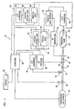
- system 10 of the invention preferably comprises pressurized gas source 12 connected to receiving tank 14 through pressurized gas flow line 16 and releasable hose connector assembly 18; gas supply valve 20, three way vent valve 45 and pressure transducer 24 disposed in gas flow line 16 to control the flow of pressurized gas between gas source 12 and receiving tank 14; temperature transducer 22 disposed inside receiving tank 14; analog-to-digital converters 26, 36; system computer 38; and display 40.
- Gas supply valve 20 is preferably a two position valve that is selectively opened and closed by electronically actuated solenoid 28 in response to signals received from computer 38. A typical response time for valve 20 is about 120 microseconds. Solenoid 28 can be hard-wired to computer 38 as shown in FIG.
- Pressurized gas source 12 can be a large volume storage tank, a pressurized gas supply line, a compressor discharge line, or any combination of these elements suitable for use in supplying gas to receiving tank 14 in an amount and at a pressure great enough to achieve the desired fill rate, fill level and pressure.
- a particularly preferred gas source 12 for supplying pressurized gas to receiving tank 14 is a system as shown and described in U.S. 5,351,726, which is incorporated by reference herein. It should be understood for purposes of the present invention that pressurized gas source 12 can include both rapid-fill and slow-fill sources, together with means for controlling the source from which the gas is supplied in response to signals generated by computer 38.
- rapid-fill is generally understood to apply to fill rates exceeding about 200 cfm per tank, while the term “slow-fill” is generally understood to apply to fill rates below 200 cfm per tank, and usually to flow rates of about 30 cfm per tank or lower. It will be appreciated of course that “rapid-fill” and “slow-fill” are relative terms and that the flow rates associated with those terms can vary substantially according to the capacity of the gas supply line and according to the number and volume of receiving tank(s) being filled in a particular application. The flow rates mentioned above are exemplary of those that might reasonably be utilized in the "rapid-fill” or “slow-fill” of vehicle storage tanks such as pickup or automobile CNG storage tanks.
- rapid-fill is primarily utilized when refilling a single tank, as described herein with reference to FIGS. 1 and 2, whereas “slow-fill” is primarily utilized when simultaneously refilling a plurality of tanks as described herein with reference to FIGS. 3, 4 and 9.
- hose connector assembly 18 preferably comprises male connector 56 communicating with vehicle tank supply line 58 attached to vehicle panel 60 by nut 62, and spring-loaded female connector 54 attached to gas flow line 16.
- Female connector 54 and male connector 56 both preferably comprise integral check valves (not visible in FIG. 8) that are locked open whenever the connection is made.
- Three-way vent valve 45 is preferably installed at the dispensing island or refueling dock just upstream of hose connector assembly 18.
- Valve 45 preferably comprises valve body 82 containing a valve member that is actuated by rotating handle 84 to selectively establish fluid communication between gas flow line 16 and either tank supply line 58 or vent line 88, or alternatively, to block fluid communication between gas flow line 16 and tank supply line 58.
- rotating handle 84 By selectively rotating valve handle 84 to the vent position after refueling, the operator is able to relieve the gas pressure inside hose connector assembly 18 to permit disengagement of female connector 54 from male connector 56.
- Three-way vent valve 45 and quick-connect hose connector assembly 18 are commercially available from well known industry vendors such as Stäubli, Swagelok, Parker Hannefin and Hoke Gyrolok.
- RF antenna loops 42, 44 are attached to male and female connectors 56, 54, respectively, and as hose connector assembly 18 is connected, the two RF antennae are brought close enough that data transfer can occur as discussed in greater detail below.
- Pressure transducer 24 is desirably disposed in gas flow line 16 between supply valve 20 and three way vent valve 45, and generates a signal corresponding to the line pressure that is forwarded through analog-to-digital converter 36 to computer 38.
- a significant feature of the present invention is the disposition of temperature transducer 22 inside receiving tank 14.
- a preferred temperature transducer 22 for use in the present invention is further described and explained in relation to FIGS. 5-7.
- temperature transducer 22 is desirably made of 304 stainless steel and is secured by threads 66 to an orifice in the end wall of receiving tank 14 that is opposite fuel inlet port 43 as shown in FIG. 1.
- the free end of probe portion 64 of temperature transducer 22 desirably extends inside receiving tank 14 to a point at or near the centroid of the tank, or at least along the centerline of the tank, in order to obtain temperature data that is representative of the gas temperature inside the tank. Referring to FIGS.
- probe portion 64 of temperature transducer 22 is desirably a tubular member having a closed end with a wall thickness that is relatively thin when compared to the wall thickness of receiving tank 14.
- Wire 68 comprising electrical conductors 70, 72 preferably extends into probe portion 64, and wire filaments 74, 76 attached to conductors 70, 72, respectively, are joined to each other at bead 78, which is also grounded to the interior surface of end wall 80 of probe portion 64.
- the volume of gas inside receiving tank 14 and the desired finish pressure can be determined or recalculated by computer 38 at any time based upon the actual temperature of the gas inside receiving tank 14.
- finish pressure refers to the pressure inside receiving tank 14 whenever the gas fill level is within a predetermined range, preferably within about 1.5%, of the standard condition volume at the rated maximum standard condition pressure for the tank.
- the signal from temperature transducer 22 can be relayed to computer 38 by any of several conventional, commercially available devices or systems as desired. Three such alternative devices are depicted diagrammatically in FIG. 1.
- the temperature data signal generated by temperature transducer 22 is routed first to analog-to-digital converter 26 and vehicle data module 32. (Although shown separately in FIG. 1, it is understood that converter 26 can be a part of the circuitry of vehicle data module 32.)
- the signal for the digitized temperature data is directed through RF transmitter 34 to antenna 42, and then picked up by antenna 44 and directed through RF receiver 46 to computer 38.
- the signal from temperature transducer 22 can alternately be routed to system computer 38 through a hard-wired connection utilizing releasably interconnectable vehicle jack 50 and control system jack 52, both of which are depicted schematically inside dashed boundary 48.
- Jacks 50, 52 can be built into the respective male and female connectors 56, 54 of hose connector assembly 18 or can be situated at any other point reasonably accessible to the operator during refueling.
- the signal from temperature transducer 22 can alternately be routed to system computer 38 through a hard-wired connection utilizing releasably interconnectable vehicle jack 92 and control system jack 94 and through analog-to-digital converter 96, which are depicted schematically inside dashed boundary 90.
- Jacks 92, 94 can be built into the respective male and female connectors 56, 54 of hose connector assembly 18 or can be situated at any other point reasonably accessible to the operator during refueling.
- point of sale authorization or fuel pump security in a self-serve fleet operation can be controlled by a credit card or "card lock" system.
- a credit card or "card lock” system With some prior art systems, each employee or customer is issued a magnetic card and assigned a personal identification (“PIN") number. After the magnetic card is scanned, the person requesting fuel is asked to enter the PIN number. The PIN number helps prevent unauthorized use of the magnetic card, but falls short of securing fuel from unauthorized use. For example, an employee having a magnetic card and PIN number can fuel an unauthorized vehicle or an unauthorized auxiliary container even with the card lock system in place. At best, record keeping is difficult, particularly if vehicles are rotated or reassigned to other operators.
- the CNG refueling system 10 disclosed herein is desirably adapted to incorporate a vehicle point of sale authorization feature that eliminates any employee input of data.
- the vehicle data module of each vehicle is desirably programmed to transmit to computer 38 a discrete alphanumeric identification code such as, for example, the 14 character manufacturer's vehicle identification number.
- the water volume, maximum allowable pressure and maximum operating pressure for receiving tank 14 can also be transmitted to system computer 38 at this time if not already stored in the computer's memory (or as a cross-check against the values stored in memory).
- the transmitted code must match up with one of a list of preauthorized codes in the system computer 38 in order to initiate the refueling cycle, thereby providing very reliable security against unauthorized use.
- the vehicle data module can be programmed to transmit back to the system computer other information such as, for example, the odometer readings for the respective mileage driven under gasoline or CNG power, engine hours for both fuels, and the like.
- the transmitter, receiver and antennae used for this purpose are the same transmitter 34, receiver 46 and antennae 42, 44 described above for use in transmitting temperature data for receiving tank 14.
- the error-free transmission distance is preferably controlled so that the communication between the vehicle and fuel hose is broken if the fuel hose is disconnected from the vehicle.
- the communication between the vehicle and fuel hose is continuously monitored during fueling and the fuel dispenser is turned off if the signal is lost. This prevents the system from dispensing CNG to anything other than an authorized vehicle.
- a jack system as represented inside dashed outline 48 of FIG. 1 is used for transmitting temperature data to computer 38 through vehicle data module 32, then other information such as vehicle identification data, tank water volume, manufacturer's pressure ratings, and the like, can also be transmitted to system computer 38 using this data link.
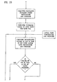
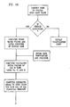
- Computer 38 then calculates the volume of CNG that receiving tank 14 will hold at its maximum operating pressure at 70°F, reads the initial temperature in receiving tank 14 as determined by temperature transducer 22 and the initial pressure as determined by pressure transducer 24, calculates the initial volume of gas in receiving tank 14 using the water volume of the tank and the initial tank temperature and pressure, estimates the finish temperature and pressure for receiving tank 14, signals solenoid 28 to open valve 20, and signals pressurized gas source 12 to commence rapid filling of receiving tank 14.
- temperature transducer 22 and pressure transducer 24 continue to forward real time temperature and pressure data to computer 38, which repeatedly recalculates the gas volume inside receiving tank 14 in standard cubic feet (cubic feet at standard conditions) at predetermined intervals.
- Computer 38 compares the volume calculated from the real time temperature and pressure inside receiving tank 14 with the previously calculated volume of gas that receiving tank 14 will hold at the maximum allowable operating pressure and 70°F. If the actual gas volume is still lower, computer 38 calculates a new estimated finish temperature and pressure and determines whether or not the actual tank pressure is within some predetermined range, preferably within about 200 psi, of the reestimated finish pressure.
- computer 38 next determines whether the actual gas volume in receiving tank 14 is within some predetermined range, preferably about 1.5%, of the volume the tank will hold at its rated pressure at 70°F. (The value of 1.5% is derived from the combined error ranges of temperature transducer 22 and pressure transducer 24.) If the volume of gas inside receiving tank 14 is within about 1.5%, computer 38 signals solenoid 28 to close valve 20.
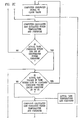
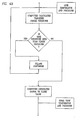
- computer 38 again reads the real time temperature and pressure of receiving tank 14, calculates a new estimated finish temperature and pressure, and signals pressurized gas source 12 to switch from "rapid-fill” to "slow-fill.”
- rapid-fill and “slow-fill” are simply intended as relative terms and that the particular flow rates associated with the terms can vary according to the capacities of the equipment utilized.
- the estimated finish pressure should always be lower than the manufacturer's maximum allowable pressure for receiving tank 14 and that system computer 38 will generate a signal for solenoid 28 to close supply valve 20 at any time the pressure as measured by pressure transducer 24 exceeds the manufacturer's maximum allowable pressure for receiving tank 14 when adjusted for the actual tank temperature as measured by temperature transducer 22 inside tank 14.
- computer 38 again reads the real time temperature and pressure received from temperature transducer 22 and pressure transducer 24, recalculates the volume of gas in receiving tank 14 in standard cubic feet using the actual tank temperature and pressure, and again determines whether or not the actual gas volume inside the receiving tank 14 is within about 1.5% of the standard condition volume (rated pressure at 70°F).
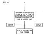
- computer 38 calculates the final volume of gas inside the tank and subtracts the initial volume to determine the volume of gas dispensed.
- Additional computations can be made regarding fuel usage, mileage, cost or the like, and the resultant data can be displayed as desired, stored electronically, or relayed back to vehicle data module 32 through a hard-wired connection such as that shown alternatively inside dashed line 48 in FIG. 1, or through another transmitter and receiver not depicted in FIG. 1.
- Three-way vent valve 45 is then turned to the vent position, releasing gas from hose connector assembly 18 through vent line 88 as seen in FIG. 8 to permit manual separation of the male and female connectors 56, 54.
- the check valves disposed inside hose connector assembly 18 prevent loss of pressurized gas from inside receiving tank 14 when hose connector assembly 18 is disconnected.
- a system and method are also disclosed for simultaneously "slow-filling" or “time-filling” (terms used synonymously herein) a plurality of receiving tanks with a pressurized gas through a plurality of hoses connected to a single manifold.
- a system of this type might be used, for example, by a fleet operator in situations where numerous vehicles having receiving tanks with substantially the same pressure ratings are kept and serviced in a common area overnight. Because the receiving tanks are filled more slowly than with the embodiment of the invention previously described, the adiabatic heat is dissipated through the tank walls, and the temperature of the gas inside the receiving tanks remains close to the ambient temperature. Because tank sizes and initial fill levels will likely vary from vehicle to vehicle, however, temperature and pressure transducers are desirably provided for each receiving tank to permit the calculation of initial and final gas volumes for each tank.
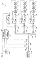
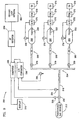
- system 100 of the invention preferably comprises pressurized gas source 12 connected to dispensing manifold 114 by gas flow line 116; three-way vent valves 170 and hose connector assemblies 166 for use in establishing gas flow communication between manifold 114 and receiving tanks 160, 162, 164; temperature transducers 122 disposed in each receiving tank and temperature transducer 180 installed in gas flow line 116; pressure transducers 178 installed in each receiving tank and pressure transducer 124 installed in gas flow line 116; analog-to-digital converters 172; vehicle data modules 173, 174, 175 for the various vehicles; RF transmitters 176; RF receiver 134; analog-to-digital converter 136; system computer 138; valve 120 disposed in gas flow line 116 and controlled by solenoid 128 in response to signals received from computer 138; and display 140.
- Hose connector assemblies 166 are desirably of the type previously described in relation to FIG. 8, which embody an RF antenna on both the male and female sides of the assemblies. Although only three receiving tanks 160, 162, 164 are shown in FIG. 3, it is understood that a plurality of additional tanks having substantially the same pressure ratings can likewise be connected to the manifold line 115 if desired.
- pressurized gas dispensing system 100 is used to "slow-fill" a plurality of receiving tanks is further described and explained in relation to FIGS. 4A to 4C.
- hose connector assemblies 166 have connected each of receiving tanks 160, 162, 164 to dispensing manifold 114, three-way vent valves 170 are desirably opened and authorization procedures are desirably initiated as discussed above in relation to system 10 for reasons of safety and security.
- tank water volumes and pressure ratings for receiving tanks 160, 162, 164 can be transmitted to system computer 138 from vehicle data modules 174, 175, 176 through transmitter 176 and receiver 136 as previously discussed in relation to system 10, or by any other similarly effective means (one of which is described below in relation to system 200 of FIG. 9).
- Initial tank temperature and pressure data are also transmitted to computer 138 from temperature transducers 122 and pressure transducers 178, and computer 138 calculates initial gas volumes for each receiving tank 160, 162, 164.
- Computer 138 then signals solenoid 128 to open valve 120, permitting pressurized gas to flow through manifold 114, valves 170 and into receiving tanks 160, 162, 164. Because pressurized gas entering manifold 114 from pressurized gas source 112 will seek the path of least resistance, the receiving tank(s) having the lowest initial pressure will equalize with the other(s) before gas will begin entering the fuller tanks.
- temperature and pressure data are communicated to computer 138 through analog-to-digital converter 136, and computer 138 calculates the targeted finish pressure.
- system computer 138 of system 100 can be programmed so that if the pressure as determined by pressure transducer 124 drops by a predetermined amount (as might be experienced due to gradual cooling) prior to the time that the receiving tanks are disconnected from the refueling system, computer 138 will recalculate the estimated finish pressure and will signal solenoid 128 to reopen valve 120 to resume slow-filling the receiving tanks until the reestimated finish pressure is achieved.
- FIG. 9 depicts pressurized gas dispensing system 200 comprising pressurized gas source 212, gas flow line 216, gas dispensing manifold 214, three-way vent valves 270, hose connector assemblies 266, ground loop antenna 250, RF receiver 234, computer 238, analog-to-digital converter 236, display 240, solenoid 228, valve 220, pressure transducer 224 and temperature transducer 280.
- temperature transducer is not in direct thermal contact with the gas supply line 216, but is disposed so as to measure ambient temperature at the refueling site.
- Ground loop antenna 250 of system 200 is a preferred vehicle - specific authorization means that can be buried in the driveway entering the refueling area for use in downloading information such as vehicle identification, mileage, tank water volume, rated pressures, initial tank temperatures and pressures, and the like, from vehicle data modules 273 as vehicles approach the refueling area.
- the entryway to the refueling area is desirably constructed with an automated gate or other similarly effective means that will deny access to the refueling area for unauthorized vehicles.
- Receiving tanks 260, 262, 264 are desirably provided with temperature transducers 222, pressure transducers 278, analog-to-digital converters 272, vehicle data modules 273 and RF transmitters 276.
- hose connector assemblies 266 do not comprise RF antennae, so ending tank temperature and pressure data from temperature transducers 222 and pressure transducers 278, or any other data not previously downloaded to the ground loop antenna 250, are transmitted to computer 238 from RF transmitters 276 to RF receiver 234 as vehicles exit the refueling area. The volume of dispersed gas is then determined by comparing the exit data to the entrance data.
- System 200 is otherwise configured and functions in the same way as system 100 previously described.
- pressurized gas particularly CNG
- POS point of sale
- FDM automated fleet data management
- a computer is used to calculate the volume of gas dispensed through use of formulae involving the pressure, volume and temperature (“PUT") relationship of gases.
- PUT pressure, volume and temperature
- Data pertaining to vehicle identification, odometer readings, rated tank pressure, tank pressure, tank temperature, fuel utilization, and the like can be communicated to and from the computer as described above through the vehicle data module, through RF transmitters and receivers (above or below ground), through plug-in hard-wired connectors, or through other similarly effective means.
- the computer can be programmed to charge out the selling price to the purchaser through any combination of displays, printouts and/or electronic data storage that is desired.
- the computer can be programmed to provide the fleet manager with periodic reports on specific vehicle performance, mileage, fuel utilization, hours of operation, and the like, using data received from the vehicle data module and from the temperature and pressure sensors disposed in the vehicle tanks.
- the systems and methods disclosed herein are also applicable to more advanced vehicular fuel systems utilizing both liquid and compressed gaseous fuels, and reports can also be generated regarding the time of operation, fuel quantities used, and mileage achieved with each fuel.
Landscapes
- Engineering & Computer Science (AREA)
- Mechanical Engineering (AREA)
- General Engineering & Computer Science (AREA)
- Filling Or Discharging Of Gas Storage Vessels (AREA)
Claims (37)
- System zum Abfüllen von Druckgas aus einer Druckgasquelle in einen Aufnahmetank, wobei das System umfasst:dadurch gekennzeichnet, dass die Mittel zur Erfassung der im Inneren des Tanks herrschenden Gastemperatur im Inneren des Tanks angeordnet sind,eine Druckgasquelle;mindestens einen Aufnahmetank;Mittel, um die Quelle lösbar am Tank anzuschliessen;Mittel zur Erfassung der Gastemperatur im Inneren des Tanks und zur Erzeugung eines dazu entsprechenden Signals;Mittel zur Erfassung des Gasdruckes im Inneren des Tanks und zur Erzeugung eines dazu entsprechenden Signals;einen Computer;Mittel, um einen Strom von Druckgas in den Tank zu starten;Mittel zur Übertragung von durch die Temperatur- und Druckmittel erzeugten Signalen zum Computer in einer für den Computer erkennbaren Form;im Computer befindliche Mittel zum Empfang und zur Speicherung von Daten des Wasservolumens und des Nenndruckes des Tanks, zum Empfang und zur Speicherung von Temperatur- und Druckdaten, die dem Computer von den temperatur- und druckerfassenden Mitteln übermittelt werden, zur Berechnung des geschätzten Enddruckes des Tanks sowie zum Vergleichen des aktuellen Druckes und Gasvolumens des Tanks mit dem geschätzten Enddruck des Tanks und dem entsprechenden Gasvolumen des Tanks; undMittel, um den Strom von Druckgas zum Tank zu beendigen, sobald das Gasvolumen im Tank oder der Gasdruck im Tank einen vorbestimmten Wert erreicht;
dass die Daten des Wasservolumens des Tanks, welche von besagten, im Computer befindlichen Mitteln zum Empfang und zur Speicherung empfangen und gespeichert werden, die vom Hersteller gelieferten Daten des Wasservolumens sind,
dass die im Computer befindlichen Mittel auch für eine auf der Temperatur und dem Druck des Tanks beruhende periodische Berechnung des Gasvolumens im Tank vorgesehen sind, und
dass die im Computer befindlichen Mittel zur Berechnung des geschätzten Enddruckes des Tanks für eine periodische solche Berechnung vorgesehen sind. - System nach Anspruch 1, wobei das Druckgas komprimiertes Erdgas ist.
- System nach Anspruch 1, weiterhin umfassend automatisierte Autorisierungsmittel.
- System nach Anspruch 3, wobei die Mittel, um einen Strom von Druckgas in den Tank zu starten, mindestens ein Ventil sowie Mittel zur Steuerung des Ventils als Antwort auf ein durch die Autorisierungsmittel erzeugtes Signal umfasst.
- System nach Anspruch 1, wobei die Übertragungsmittel elektronische Signalerzeugungs-, -übermittlungs- und -empfangsmittel umfassen.
- System nach Anspruch 1, wobei die Mittel zur Beendigung des Stromes von Druckgas in den Tank den Strom beendigen, sobald das Gasvolumen im Inneren des Tanks einen vorbestimmten Wert erreicht.
- System nach Anspruch 1, wobei die Mittel zur Beendigung des Stromes von Druckgas in den Tank den Strom beendigen, sobald der Gasdruck im Tank einen vorbestimmten Wert erreicht.
- System nach Anspruch 1, umfassend Mittel, um zu jedem Zeitpunkt, nachdem der Strom von Druckgas in den Tank gestartet worden ist, einen dem Gasvolumen im Inneren des Tanks entsprechenden Wert zu berechnen und speichern.
- System nach Anspruch 1, umfassend Mittel zur Berechnung, Darstellung und Speicherung des in den Tank abgefüllten Gasvolumens.
- System nach Anspruch 1, umfassend Mittel zur Berechnung, Darstellung und Speicherung der Kosten des in den Tank abgefüllten Gases.
- System nach Anspruch 1, umfassend Mittel zum gleichzeitigen Abfüllen von Druckgas von der Druckgasquelle zu einer Vielzahl von Aufnahmetanks.
- System nach Anspruch 1, umfassend Mittel, um den Strom von Druckgas von der Druckgasquelle zum Aufnahmetank auf eine gewünschte Flussrate zu regeln.
- System nach Anspruch 3, wobei der Aufnahmetank ein Vorratstank eines Fahrzeuges ist und wobei das automatisierte Autorisierungsmittel fahrzeugspezifisch ist.
- System nach Anspruch 1, wobei das Mittel zur Erfassung der Gastemperatur im Inneren des Tanks und zur Erzeugung eines dazu entsprechenden Signals einen in das Tank ragenden Temperaturwandler umfassen.
- System nach Anspruch 1, wobei das Mittel zur Erfassung des Gasdruckes im Inneren des Tanks und zur Erzeugung eines dazu entsprechenden Signals ein mit dem Tank in Fluidverbindung stehender Druckwandler ist.
- System nach Anspruch 1, wobei die Mittel, um die Quelle am Tank lösbar anzuschliessen, einen flexiblen Schlauch mit einem lösbaren Anschlussmittel umfassen.
- System nach Anspruch 1, wobei die Mittel, um die Quelle am Tank lösbar anzuschliessen, für die Übermittlung von Daten zum Computer verwendbare Mittel umfassen.
- Verfahren zum Abfüllen von Druckgas aus einer Druckgasquelle in einen Aufnahmetank, wobei das Verfahren die Schritte umfasst:dadurch gekennzeichnet, dass das eingelesene und gespeicherte Wasservolumen das vom Hersteller angegebene Wasservolumen ist;Einlesen und Speichern in einem Computer des Wasservolumens und des Nenndruckes des Tanks;lösbares Anschliessen einer Gasstromleitung von der Quelle an den Tank;Erfassen und Übermitteln an den Computer einer im Inneren des Tanks herrschenden Anfangstemperatur und eines Anfangsdruckes;Berechnen und Speichern eines anfänglichen Gasvolumens des Tanks;Starten eines Stromes von Druckgas von der Quelle in den Tank;periodisches Erfassen und Übermitteln an den Computer der im Inneren des Tanks herrschenden Temperatur und Gasdruck;periodisches Wiederberechnen des Gasvolumens im Inneren des Tanks;Berechnen eines geschätzten Enddruckes des Gases im Inneren des Tanks;Vergleichen des aktuellen Tankdruckes und Gasvolumens mit dem geschätzten Enddruck und dem entsprechenden Gasvolumen im Tank; undBeendigen des Stromes von Druckgas zum Tank, sobald das Gasvolumen oder der Gasdruck im Tank einen vorbestimmten Wert erreicht,
dass das anfängliche und periodische Erfassen des Druckes im Inneren des Tanks durch einen im Inneren des Tanks angeordneten Temperatur-Sensor bewerkstelligt wird;
und dass das Berechnen eines geschätzten Enddrucks des Gases im Inneren des Tanks periodisch durchgeführt wird. - Verfahren nach Anspruch 18, wobei das Druckgas komprimiertes Erdgas ist.
- Verfahren nach Anspruch 18, weiterhin umfassend den Schritt des Bestätigens der Benutzer-Autorisierung vor dem Starten des Stromes von Druckgas.
- Verfahren nach Anspruch 18, umfassend den Schritt des Beendigens des Stromes von Druckgas zum Tank, sobald das Gasvolumen im Inneren des Tanks einen vorbestimmten Wert erreicht.
- Verfahren nach Anspruch 18, umfassend den Schritt des Beendigens des Stromes von Druckgas zum Tank, sobald der Gasdruck im Inneren des Tanks einen vorbestimmten Wert erreicht.
- Verfahren nach Anspruch 18, umfassend den Schritt des gleichzeitigen Abfüllens von Druckgas aus der Druckgasquelle in eine Vielzahl von Aufnahmetanks.
- Verfahren nach Anspruch 18, umfassend den Schritt des Regelns des Stromes von Druckgas von der Druckgasquelle zum Aufnahmetank auf eine bestimmte Flussrate.
- Verfahren nach Anspruch 18, wobei der Aufnahmetank ein Vorratstank eines Fahrzeugs ist.
- Verfahren nach Anspruch 18, umfassend die Schritte des Berechnens, Speicherns und Darstellens des von der Quelle in den Tank geleiteten Gasvolumens.
- Verfahren nach Anspruch 18, umfassend die Schritte des Berechnens, Speicherns und Darstellens der Kosten des von der Quelle in den Tank geleiteten Gases.
- System zur Bestimmung der von einer Druckgasquelle in einen Aufnahmetank bekannten Wasservolumens abgefüllten Menge eines vorbestimmten Druckgases, wobei das System umfasst:dadurch gekennzeichnet, dass das System weiterhin umfasst:Mittel zur Bestimmung der Anfangstemperatur und des Anfangsdruckes im Inneren des Aufnahmetanks;Mittel zur Berechnung und Speicherung des Anfangsvolumens des Gases im Inneren des Aufnahmetanks; und Mittel zur Bestimmung der Endtemperatur und des Enddruckes im Inneren des Aufnahmetanks;Mittel zur Berechnung des Endvolumens des Gases im Inneren des Aufnahmetanks; undMittel zur Bestimmung der Differenz zwischen dem Anfangsund Endvolumen des Gases im Inneren des Aufnahmetanks;und dass die Mittel zur Bestimmung der Anfangs- und Endtemperaturen im Inneren des Aufnahmetanks angeordnet sind.
- System nach Anspruch 28, wobei die Mittel zur Bestimmung der Anfangs- und Endtemperaturen im Inneren des Aufnahmetanks einen in der Tankwand installierten Temperaturwandler umfassen.
- System nach Anspruch 28, wobei die Mittel zur Bestimmung der Anfangs- und Enddrucke im Inneren des Aufnahmetanks einen in der Tankwand installierten Druckwandler umfassen.
- System nach Anspruch 28, wobei das Mittel zur Berechnung der Anfangs- und Endvolumen des Gases im Inneren des Tanks ein persönlicher Computer ist.
- System nach Anspruch 18, wobei das Mittel zur Bestimmung der Differenz zwischen dem Anfangs- und Endvolumen des Gases im Inneren des Aufnahmetanks ein persönlicher Computer ist.
- Verfahren zum Wiederauffüllen eines Vorratstanks mit einem Druckgas, wobei das Verfahren die folgenden Schritte umfasst:dadurch gekennzeichnet, dass das Verfahren weiter umfasst:Bestimmen des Superkompressibilitätsfaktors des Druckgases;Bestimmen des Volumens des Vorratstanks;Bestimmen der Anfangstemperatur und des Anfangsdruckes im Inneren des Tanks;Berechnen des Volumens des Druckgases im Inneren des Tanks vor dem Wiederauffüllen unter Verwendung des bezüglich der Superkompressibilität des Druckgases korrigierten idealen Gasgesetzes;Starten eines Stromes von Druckgas in den Vorratstank;Bestimmen eines gewünschten Endfülldruckes;Überwachen des Druckes im Inneren des Vorratstanks während des Wiederauffüllens;Beendigen des Stromes von Druckgas, sobald der Druck im Inneren des Vorratstanks einen gewünschten Endfülldruck erreicht; undBestimmen der Endtemperatur und des Enddruckes im Inneren des Tanks;Berechnen des Volumens des Druckgases im Inneren des Tanks nach dem Wiederauffüllen unter Verwendung des bezüglich der Superkompressibilität des Druckgases korrigierten idealen Gasgesetzes; undBestimmen des Volumens des während des Wiederauffüllens abgefüllten Gases durch Subtraktion des Gasvolumens im Inneren des Tanks vor dem Wiederauffüllen vom Gasvolumen im Inneren des Tanks nach dem Wiederauffüllen;und dass das Bestimmen der Anfangs- und Endtemperaturen des Tanks mittels eines im Inneren des Tanks angebrachten Temperatur-Sensors durchgeführt wird.
- Verfahren nach Anspruch 33, umfassend die zusätzlichen Schritte des Überwachens der Temperatur im Inneren des Vorratstanks während des Wiederauffüllens sowie des erneuten Bestimmens des gewünschten Endfülldruckes als Antwort auf die Temperaturänderungen im Inneren des Vorratstanks während des Wiederauffüllens.
- Verfahren nach Anspruch 34, umfassend den zusätzlichen Schritt des Berechnens des Druckgasvolumens im Inneren des Tanks während des Wiederauffüllens unter Verwendung des bezüglich der Superkompressibilität des Druckgases korrigierten idealen Gasgesetzes.
- Verfahren nach Anspruch 35, wobei der Strom von Druckgas beendet wird, sobald das Druckgasvolumen im Inneren des Tanks einen vorbestimmten Wert erreicht hat.
- Verfahren nach Anspruch 33, umfassend den zusätzlichen Schritt des Reduzierens des Stromes von Druckgas, sowie sich der Druck im Inneren des Gefässes dem gewünschten Endfüllungsdruck nähert.
Applications Claiming Priority (3)
| Application Number | Priority Date | Filing Date | Title |
|---|---|---|---|
| US08/377,975 US5628349A (en) | 1995-01-25 | 1995-01-25 | System and method for dispensing pressurized gas |
| US377975 | 1995-01-25 | ||
| PCT/US1996/000039 WO1996022915A1 (en) | 1995-01-25 | 1996-01-24 | System and method for dispensing pressurized gas |
Publications (3)
| Publication Number | Publication Date |
|---|---|
| EP0805765A1 EP0805765A1 (de) | 1997-11-12 |
| EP0805765A4 EP0805765A4 (de) | 1998-01-28 |
| EP0805765B1 true EP0805765B1 (de) | 2003-06-04 |
Family
ID=23491225
Family Applications (1)
| Application Number | Title | Priority Date | Filing Date |
|---|---|---|---|
| EP96902060A Expired - Lifetime EP0805765B1 (de) | 1995-01-25 | 1996-01-24 | System und verfahren zum abfüllen von druckgas |
Country Status (6)
| Country | Link |
|---|---|
| US (1) | US5628349A (de) |
| EP (1) | EP0805765B1 (de) |
| CN (1) | CN1094578C (de) |
| AU (1) | AU4651596A (de) |
| CA (1) | CA2208763C (de) |
| WO (1) | WO1996022915A1 (de) |
Families Citing this family (104)
| Publication number | Priority date | Publication date | Assignee | Title |
|---|---|---|---|---|
| US5810058A (en) * | 1996-03-20 | 1998-09-22 | Gas Research Institute | Automated process and system for dispensing compressed natural gas |
| US5762118A (en) * | 1996-11-05 | 1998-06-09 | I C E M Enterprises Inc. | Apparatus and method for the cordless remote control of a filling function of a mobile vehicle |
| DE19653048A1 (de) * | 1996-12-19 | 1998-06-25 | Messer Griesheim Gmbh | Verfahren und Vorrichtung zum Überwachen der Befüllung eines Kryotanks |
| US5868176A (en) * | 1997-05-27 | 1999-02-09 | Gas Research Institute | System for controlling the fill of compressed natural gas cylinders |
| US5970786A (en) * | 1997-09-25 | 1999-10-26 | Smith; Robert S. | Method for measuring compressed natural gas |
| DE19915779B4 (de) * | 1999-04-08 | 2007-10-31 | Air Liquide Deutschland Gmbh | Abfüllstand zur Herstellung von Präzisionsgasgemischen |
| FR2801370B1 (fr) | 1999-11-22 | 2002-02-01 | Cryolor | Installation de stockage d'un gaz liquefie sous pression |
| JP4490557B2 (ja) * | 2000-06-09 | 2010-06-30 | 本田技研工業株式会社 | 水素急速充填方法 |
| FR2812958B1 (fr) * | 2000-08-11 | 2002-11-08 | Thomson Csf | Systeme de maintenance pour un ensemble d'equipements |
| DE50113779D1 (de) * | 2000-11-08 | 2008-05-08 | Greenfield Ag | Verfahren zum Befüllen eines Fahrzeugtanks mit Gas |
| EP1205704B1 (de) * | 2000-11-08 | 2008-03-26 | GreenField AG | Verfahren zum Befüllen eines Fahrzeugtanks mit Gas |
| US6698462B2 (en) * | 2001-04-30 | 2004-03-02 | Hewlett-Packard Development Company, L.P. | Automatic solution dispenser |
| DE10142757C1 (de) * | 2001-08-31 | 2003-04-17 | Messer Griesheim Gmbh | Betankungseinrichtung und Verfahren zur Betankung von kryokraftstoffbetriebenen Fahrzeugen |
| EP1312854A1 (de) * | 2001-11-19 | 2003-05-21 | Linde Aktiengesellschaft | Gaszuführvorrichtung |
| US6619336B2 (en) | 2002-02-14 | 2003-09-16 | Air Products And Chemicals, Inc. | System and method for dispensing pressurized gas |
| US6782928B2 (en) * | 2002-03-15 | 2004-08-31 | Lg.Philips Lcd Co., Ltd. | Liquid crystal dispensing apparatus having confirming function for remaining amount of liquid crystal and method for measuring the same |
| US6779350B2 (en) | 2002-03-21 | 2004-08-24 | Ritchie Enginerring Company, Inc. | Compressor head, internal discriminator, external discriminator, manifold design for refrigerant recovery apparatus and vacuum sensor |
| US6832491B2 (en) * | 2002-03-21 | 2004-12-21 | Ritchie Engineering Company, Inc. | Compressor head, internal discriminator, external discriminator, manifold design for refrigerant recovery apparatus |
| US6805172B2 (en) * | 2002-09-06 | 2004-10-19 | Kendro Laboratory Products, Inc. | Enhanced/proactive CO2/O2 gas control |
| US6810924B2 (en) * | 2003-03-17 | 2004-11-02 | Praxair Technology, Inc. | Compressed gas stream introduction method and filling station |
| US7788048B2 (en) * | 2003-04-24 | 2010-08-31 | Hewlett-Packard Development Company, L.P. | Apparatus and method for integrating a fuel supply and a fuel level sensing pressure sensor |
| US20070113575A1 (en) * | 2003-12-05 | 2007-05-24 | Ritchie Engineering Company, Inc. | Valve manifold assembly |
| US20050126200A1 (en) * | 2003-12-05 | 2005-06-16 | Ajit Ramachandran | Single valve manifold |
| US7168464B2 (en) * | 2004-09-09 | 2007-01-30 | Pinnacle Cng Systems, Llc | Dual-service system and method for compressing and dispensing natural gas and hydrogen |
| FR2879719B1 (fr) * | 2004-12-22 | 2007-11-23 | Air Liquide | Procede de controle du remplissage de reservoirs de gaz sous pression |
| US20060180237A1 (en) * | 2005-02-17 | 2006-08-17 | Hoke Bryan C Jr | System and method for dispensing compressed gas |
| US7152637B2 (en) | 2005-02-17 | 2006-12-26 | Air Products And Chemicals, Inc. | Method and apparatus for dispensing compressed gas |
| US7762289B2 (en) * | 2005-06-21 | 2010-07-27 | Respironics, Inc. | Method and related system of filling therapeutic gas cylinders |
| US7568507B2 (en) * | 2005-12-06 | 2009-08-04 | Air Products And Chemicals, Inc. | Diagnostic method and apparatus for a pressurized gas supply system |
| RU2299375C1 (ru) * | 2006-02-01 | 2007-05-20 | Военная академия Ракетных войск стратегического назначения имени Петра Великого | Способ распределения расходов газа и устройство для его осуществления |
| US8020589B2 (en) | 2007-01-04 | 2011-09-20 | Air Products And Chemicals, Inc. | Hydrogen dispensing station and method of operating the same |
| DE102007012080A1 (de) * | 2007-03-13 | 2008-09-18 | Linde Ag | Verfahren zum Befüllen eines Wasserstoff-Speicherbehälters |
| US8286670B2 (en) * | 2007-06-22 | 2012-10-16 | L'air Liquide Societe Anonyme Pour L'etude Et L'exploitation Des Procedes Georges Claude | Method for controlled filling of pressurized gas tanks |
| FR2919376B1 (fr) * | 2007-07-26 | 2010-01-29 | Air Liquide | Systeme de robinet pour bouteille de fluide sous pression. |
| US7891350B2 (en) * | 2007-12-06 | 2011-02-22 | Ausco, Inc. | Self-contained chargeable gas supply system for pneumatic store ejection utilizing a removable, replaceable and on-board rechargeable gas storage vessel |
| US8986253B2 (en) | 2008-01-25 | 2015-03-24 | Tandem Diabetes Care, Inc. | Two chamber pumps and related methods |
| US8408421B2 (en) | 2008-09-16 | 2013-04-02 | Tandem Diabetes Care, Inc. | Flow regulating stopcocks and related methods |
| CA2737461A1 (en) | 2008-09-19 | 2010-03-25 | Tandem Diabetes Care, Inc. | Solute concentration measurement device and related methods |
| JP5525188B2 (ja) * | 2009-06-09 | 2014-06-18 | 本田技研工業株式会社 | 水素充填装置及び水素充填方法 |
| FR2948438B1 (fr) * | 2009-07-27 | 2015-04-03 | Air Liquide | Procede d'estimation du volume d'un reservoir de gaz sous pression. |
| US8926561B2 (en) | 2009-07-30 | 2015-01-06 | Tandem Diabetes Care, Inc. | Infusion pump system with disposable cartridge having pressure venting and pressure feedback |
| JP5489573B2 (ja) * | 2009-07-30 | 2014-05-14 | トヨタ自動車株式会社 | ガス充填システム及びガス充填装置 |
| JP5474436B2 (ja) | 2009-07-30 | 2014-04-16 | トヨタ自動車株式会社 | ガス充填システム |
| JP5287994B2 (ja) * | 2009-10-19 | 2013-09-11 | トヨタ自動車株式会社 | ガス充填装置、ガス充填システム、ガス充填方法及び移動装置 |
| NO332687B1 (no) * | 2009-10-21 | 2012-12-10 | Nel Hydrogen As | Fremgangsmate for operasjonen og styring ved gassfylling |
| US8534327B2 (en) * | 2009-11-16 | 2013-09-17 | Toyota Jidosha Kabushiki Kaisha | Gas charging apparatus and gas charging method |
| JP5328617B2 (ja) * | 2009-11-18 | 2013-10-30 | トヨタ自動車株式会社 | ガス充填システム、ガス充填方法、車両 |
| JP5261408B2 (ja) * | 2010-01-25 | 2013-08-14 | トヨタ自動車株式会社 | 燃料ガスステーション、燃料ガス充填システム、燃料ガス供給方法 |
| US8783303B2 (en) | 2010-04-21 | 2014-07-22 | Ryan HARTY | Method and system for tank refilling |
| US9212783B2 (en) | 2010-04-21 | 2015-12-15 | Honda Motor Co., Ltd. | Method and system for tank refilling |
| US9347614B2 (en) | 2010-04-21 | 2016-05-24 | Honda Motor Co., Ltd. | Method and system for tank refilling using active fueling speed control |
| US9605804B2 (en) | 2010-04-21 | 2017-03-28 | Honda Motor Co., Ltd. | Method and system for tank refilling using active fueling speed control |
| US9347612B2 (en) | 2010-04-21 | 2016-05-24 | Honda Motor Co., Ltd. | Method and system for tank refilling using active fueling speed control |
| US8453682B2 (en) * | 2010-05-24 | 2013-06-04 | Air Products And Chemicals, Inc. | Compressed gas dispensing method |
| DE102010027683A1 (de) * | 2010-07-20 | 2012-01-26 | Linde Aktiengesellschaft | Tankstelle mit Kommunikation |
| JP5757074B2 (ja) * | 2010-08-20 | 2015-07-29 | トヨタ自動車株式会社 | ガス充填システム及び補正方法 |
| US8783307B2 (en) * | 2010-12-29 | 2014-07-22 | Clean Energy Fuels Corp. | CNG time fill system and method with safe fill technology |
| US8973624B2 (en) * | 2011-01-27 | 2015-03-10 | GM Global Technology Operations LLC | Compressed hydrogen fueling control valve |
| US9618158B2 (en) | 2011-05-02 | 2017-04-11 | New Gas Industries, L.L.C. | Method and apparatus for compressing gas in a plurality of stages to a storage tank array having a plurality of storage tanks |
| FR2978233B1 (fr) | 2011-07-22 | 2016-05-06 | Air Liquide | Procede de remplissage d'un reservoir avec du gaz sous pression |
| US8720500B2 (en) * | 2011-10-11 | 2014-05-13 | GM Global Technology Operations LLC | Electrical architecture for passive controller wake-up during refuel |
| US20140331691A1 (en) * | 2011-12-05 | 2014-11-13 | Francesco Nettis | System and method for loading, storing and offloading natural gas from a barge |
| PL2788215T3 (pl) * | 2011-12-07 | 2020-06-15 | Agility Fuel Systems Llc | Systemy i sposoby monitorowania i kontrolowania układów paliwowych |
| US10018304B2 (en) | 2012-01-31 | 2018-07-10 | J-W Power Company | CNG fueling system |
| US10851944B2 (en) | 2012-01-31 | 2020-12-01 | J-W Power Company | CNG fueling system |
| WO2013116526A1 (en) | 2012-01-31 | 2013-08-08 | J-W Power Company | Cng fueling system |
| US9434598B2 (en) * | 2012-03-15 | 2016-09-06 | Ultimate Cng, Llc | Mobile fueling vehicle and method |
| JP5591854B2 (ja) * | 2012-03-19 | 2014-09-17 | 本田技研工業株式会社 | 移動体及びその燃料充填システム |
| CN102620136A (zh) * | 2012-04-13 | 2012-08-01 | 成都佳贝尔电子科技有限责任公司 | 永久气体充装控制装置 |
| US9180242B2 (en) | 2012-05-17 | 2015-11-10 | Tandem Diabetes Care, Inc. | Methods and devices for multiple fluid transfer |
| US9086040B2 (en) * | 2012-10-17 | 2015-07-21 | Ford Global Technologies, Llc | Fuel system degradation test using two fuel tanks |
| KR20140081030A (ko) * | 2012-12-21 | 2014-07-01 | 현대자동차주식회사 | 오염 수소 충전 방지 시스템 |
| US9395047B2 (en) * | 2013-03-01 | 2016-07-19 | Clean Energy Fuels Corp. | Compressed natural gas fleet fill management system |
| US9173998B2 (en) | 2013-03-14 | 2015-11-03 | Tandem Diabetes Care, Inc. | System and method for detecting occlusions in an infusion pump |
| US20140261865A1 (en) * | 2013-03-15 | 2014-09-18 | Compressed Energy Systems | Methods and apparatuses for recovering, storing, transporting and using compressed gas |
| CA3002762A1 (en) * | 2013-03-15 | 2014-09-15 | Bpc Acquisition Company | Lng dispenser |
| US9279541B2 (en) * | 2013-04-22 | 2016-03-08 | Air Products And Chemicals, Inc. | Method and system for temperature-controlled gas dispensing |
| FR3010481B1 (fr) * | 2013-09-12 | 2023-06-30 | Plc & Process | Procede de calcul de la pression statique lors du transfert d'un gaz entre une source de pression ou de depression et au moins un reservoir |
| US20140182561A1 (en) * | 2013-09-25 | 2014-07-03 | Eghosa Gregory Ibizugbe, JR. | Onboard CNG/CFG Vehicle Refueling and Storage Systems and Methods |
| US9605805B2 (en) * | 2013-11-04 | 2017-03-28 | Trillium Transportation Fuels, Llc | Active pressure and flow regulation system |
| EP2881645B1 (de) * | 2013-12-06 | 2019-06-26 | Stork Technical Services (RBG) Limited | System zum Wiederaufladen eines tragbaren Atemgerätes |
| WO2015100439A1 (en) | 2013-12-26 | 2015-07-02 | Tandem Diabetes Care, Inc. | Integration of infusion pump with remote electronic device |
| FR3026984A1 (fr) * | 2014-10-09 | 2016-04-15 | Dover Europe Sarl | Cartouche sans surpression inadmissible |
| US9784411B2 (en) * | 2015-04-02 | 2017-10-10 | David A. Diggins | System and method for unloading compressed natural gas |
| US10551001B2 (en) | 2015-09-03 | 2020-02-04 | J-W Power Company | Flow control system |
| US10077998B2 (en) | 2015-09-14 | 2018-09-18 | Honda Motor Co., Ltd. | Hydrogen fueling with integrity checks |
| NL2015613B1 (en) * | 2015-10-14 | 2017-05-08 | Fluidor Equipment B V | Method and system for clearing a pipe system. |
| ITUB20160404A1 (it) * | 2016-01-26 | 2017-07-26 | Global Service Design Ltd Uk Company Number 07411425 | Apparato per l'erogazione controllata di un fluido da un contenitore e relativo metodo di erogazione |
| WO2017176567A1 (en) | 2016-04-08 | 2017-10-12 | Hexagon Technology As | System with remotely controlled, pressure actuated tank valve |
| DE102017206955B4 (de) * | 2017-04-25 | 2019-04-25 | Volkswagen Aktiengesellschaft | Tankanschlussstecker und Betankungssystem |
| US20190228480A1 (en) * | 2018-01-24 | 2019-07-25 | Maverik, Inc | Generating receipts at remote fuel dispensers |
| WO2019235386A1 (ja) * | 2018-06-07 | 2019-12-12 | 本田技研工業株式会社 | ガス充填方法 |
| DE102018210961B4 (de) * | 2018-07-04 | 2021-12-09 | Audi Ag | Verfahren zum Steuern eines Auftankvorganges zum Befüllen einer Kraftstofftankeinrichtung eines Kraftfahrzeugs mit einem gasförmigen Kraftstoff, Auftankvorgangplanungseinrichtung, Auftankvorrichtung, und Kraftfahrzeug |
| US11313514B2 (en) | 2018-12-04 | 2022-04-26 | Honda Motor Co., Ltd. | Method and system for tank refueling using dispenser and nozzle readings |
| US11339926B2 (en) | 2018-12-05 | 2022-05-24 | Honda Motor Co., Ltd. | Methods and systems for improving hydrogen refueling |
| CN111486339B (zh) * | 2020-04-02 | 2022-04-15 | 北京科荣达航空设备科技有限公司 | 飞机氧气瓶自动充灌装置 |
| CN111640249A (zh) * | 2020-05-09 | 2020-09-08 | 连云港杰瑞自动化有限公司 | 一种用于lng加注船的计量计费控制装置及控制方法 |
| US11604087B2 (en) * | 2020-09-21 | 2023-03-14 | China Energy Investment Corporation Limited | Method and apparatus for calculating volume of compressed gas storage vessel, computer, and medium |
| DE102020130720A1 (de) | 2020-11-20 | 2022-05-25 | Deutsche Bahn Aktiengesellschaft | Verfahren zum befüllen eines tankbehälters eines fahrzeugs mit gasförmigem wasserstoff aus einem vorratsbehälter einer versorgungsstation |
| JP7574648B2 (ja) * | 2021-01-08 | 2024-10-29 | トヨタ自動車株式会社 | 水素充填システム |
| DE102021108717A1 (de) | 2021-04-08 | 2022-10-13 | Bayerische Motoren Werke Aktiengesellschaft | Verfahren und Vorrichtung zur Steuerung einer Betankung eines Druckbehältersystems |
| CN115681802B (zh) * | 2022-10-18 | 2025-11-14 | 厚普智慧物联科技有限公司 | 压缩天然气的加气机加气方法、装置、设备及存储介质 |
| US12345377B1 (en) * | 2024-03-08 | 2025-07-01 | Nippon Sanso Taiwan, Inc. | Stable liquefied gas supply and heating apparatus |
| EP4685385A1 (de) * | 2024-07-25 | 2026-01-28 | Hexagon Purus North America Holdings Inc. | Druckverwaltungssystem |
Family Cites Families (15)
| Publication number | Priority date | Publication date | Assignee | Title |
|---|---|---|---|---|
| US3719196A (en) * | 1970-05-06 | 1973-03-06 | Jones R Mc | Charging sequence system and process |
| US4240381A (en) * | 1979-05-08 | 1980-12-23 | Purification Sciences Inc. | Internal combustion engine system |
| US4515516A (en) * | 1981-09-30 | 1985-05-07 | Champion, Perrine & Associates | Method and apparatus for compressing gases |
| US4527600A (en) * | 1982-05-05 | 1985-07-09 | Rockwell International Corporation | Compressed natural gas dispensing system |
| US4883099A (en) * | 1986-07-22 | 1989-11-28 | Vanommeren James | Method and system for filling liquid cylinders |
| DE3873653D1 (de) * | 1987-07-23 | 1992-09-17 | Sulzer Ag | Einrichtung zum betanken eines gasbrennstoffbehaelters. |
| NZ229839A (en) * | 1988-08-15 | 1992-01-29 | Sulzer Ag | Cng refueller with temperature and pressure cut-offs |
| US4984457A (en) * | 1989-08-18 | 1991-01-15 | The United States Of America As Represented By The Administrator Of The National Aeronautics And Space Administration | Tank gauging apparatus and method |
| US5156198A (en) * | 1991-02-20 | 1992-10-20 | Hall Gerald L | Pump lock fuel system |
| US5238030A (en) * | 1991-06-27 | 1993-08-24 | Dvco | Method and apparatus for dispensing natural gas |
| US5259424A (en) * | 1991-06-27 | 1993-11-09 | Dvco, Inc. | Method and apparatus for dispensing natural gas |
| US5169295A (en) * | 1991-09-17 | 1992-12-08 | Tren.Fuels, Inc. | Method and apparatus for compressing gases with a liquid system |
| US5479966A (en) * | 1993-07-26 | 1996-01-02 | Consolidated Natural Gas Service Company, Inc. | Quick fill fuel charge process |
| US5454408A (en) * | 1993-08-11 | 1995-10-03 | Thermo Power Corporation | Variable-volume storage and dispensing apparatus for compressed natural gas |
| US5351726A (en) * | 1993-09-27 | 1994-10-04 | Wagner & Brown, Ltd. | System and method for compressing natural gas and for refueling motor vehicles |
-
1995
- 1995-01-25 US US08/377,975 patent/US5628349A/en not_active Expired - Lifetime
-
1996
- 1996-01-24 EP EP96902060A patent/EP0805765B1/de not_active Expired - Lifetime
- 1996-01-24 CA CA002208763A patent/CA2208763C/en not_active Expired - Fee Related
- 1996-01-24 CN CN96191608A patent/CN1094578C/zh not_active Expired - Lifetime
- 1996-01-24 AU AU46515/96A patent/AU4651596A/en not_active Abandoned
- 1996-01-24 WO PCT/US1996/000039 patent/WO1996022915A1/en not_active Ceased
Also Published As
| Publication number | Publication date |
|---|---|
| CA2208763A1 (en) | 1996-08-01 |
| WO1996022915A1 (en) | 1996-08-01 |
| EP0805765A1 (de) | 1997-11-12 |
| CN1169132A (zh) | 1997-12-31 |
| CN1094578C (zh) | 2002-11-20 |
| AU4651596A (en) | 1996-08-14 |
| US5628349A (en) | 1997-05-13 |
| MX9705499A (es) | 1998-10-31 |
| EP0805765A4 (de) | 1998-01-28 |
| CA2208763C (en) | 2004-04-20 |
Similar Documents
| Publication | Publication Date | Title |
|---|---|---|
| EP0805765B1 (de) | System und verfahren zum abfüllen von druckgas | |
| EP1336795B1 (de) | Vorrichtung und Verfahren zum Befördern von Druckgas | |
| US11860653B2 (en) | Preventing contamination in a bulk liquid storage tank | |
| US5360139A (en) | Liquified natural gas fueling facility | |
| US7178565B2 (en) | Self-contained mobile fueling station | |
| US6466842B1 (en) | Dispensing system for preventing unauthorized fueling | |
| US7152637B2 (en) | Method and apparatus for dispensing compressed gas | |
| JPH06510011A (ja) | 天然ガスを供給するための改良された方法及び装置 | |
| WO2009132347A1 (en) | Fuel delivery pathway control | |
| US20190291520A1 (en) | Currency Operated Automobile Fluid Dispensing and/or Recovery Assemblies and Methods | |
| WO2011123938A1 (en) | Tank identification delivery interlock system and method | |
| MXPA97005499A (en) | System and method to remove gas pressuriz | |
| US20240240758A1 (en) | System and Method for Compressed Gas Dispensing with Subsequent Venting | |
| JPH0672496A (ja) | 給油装置 |
Legal Events
| Date | Code | Title | Description |
|---|---|---|---|
| PUAI | Public reference made under article 153(3) epc to a published international application that has entered the european phase |
Free format text: ORIGINAL CODE: 0009012 |
|
| 17P | Request for examination filed |
Effective date: 19970812 |
|
| AK | Designated contracting states |
Kind code of ref document: A1 Designated state(s): CH FR GB IT LI SE |
|
| A4 | Supplementary search report drawn up and despatched |
Effective date: 19971215 |
|
| AK | Designated contracting states |
Kind code of ref document: A4 Designated state(s): CH FR GB IT LI SE |
|
| 17Q | First examination report despatched |
Effective date: 20010504 |
|
| GRAG | Despatch of communication of intention to grant |
Free format text: ORIGINAL CODE: EPIDOS AGRA |
|
| GRAG | Despatch of communication of intention to grant |
Free format text: ORIGINAL CODE: EPIDOS AGRA |
|
| GRAH | Despatch of communication of intention to grant a patent |
Free format text: ORIGINAL CODE: EPIDOS IGRA |
|
| GRAH | Despatch of communication of intention to grant a patent |
Free format text: ORIGINAL CODE: EPIDOS IGRA |
|
| GRAA | (expected) grant |
Free format text: ORIGINAL CODE: 0009210 |
|
| AK | Designated contracting states |
Designated state(s): CH FR GB IT LI SE |
|
| REG | Reference to a national code |
Ref country code: GB Ref legal event code: FG4D |
|
| REG | Reference to a national code |
Ref country code: CH Ref legal event code: EP |
|
| REG | Reference to a national code |
Ref country code: SE Ref legal event code: TRGR |
|
| REG | Reference to a national code |
Ref country code: CH Ref legal event code: NV Representative=s name: ROTTMANN, ZIMMERMANN + PARTNER AG |
|
| ET | Fr: translation filed | ||
| PLBE | No opposition filed within time limit |
Free format text: ORIGINAL CODE: 0009261 |
|
| STAA | Information on the status of an ep patent application or granted ep patent |
Free format text: STATUS: NO OPPOSITION FILED WITHIN TIME LIMIT |
|
| 26N | No opposition filed |
Effective date: 20040305 |
|
| PGFP | Annual fee paid to national office [announced via postgrant information from national office to epo] |
Ref country code: CH Payment date: 20050127 Year of fee payment: 10 |
|
| PG25 | Lapsed in a contracting state [announced via postgrant information from national office to epo] |
Ref country code: LI Free format text: LAPSE BECAUSE OF NON-PAYMENT OF DUE FEES Effective date: 20060131 Ref country code: CH Free format text: LAPSE BECAUSE OF NON-PAYMENT OF DUE FEES Effective date: 20060131 |
|
| REG | Reference to a national code |
Ref country code: CH Ref legal event code: PL |
|
| PGFP | Annual fee paid to national office [announced via postgrant information from national office to epo] |
Ref country code: SE Payment date: 20070104 Year of fee payment: 12 |
|
| PGFP | Annual fee paid to national office [announced via postgrant information from national office to epo] |
Ref country code: GB Payment date: 20070124 Year of fee payment: 12 |
|
| PGFP | Annual fee paid to national office [announced via postgrant information from national office to epo] |
Ref country code: IT Payment date: 20070528 Year of fee payment: 12 |
|
| PGFP | Annual fee paid to national office [announced via postgrant information from national office to epo] |
Ref country code: FR Payment date: 20070109 Year of fee payment: 12 |
|
| EUG | Se: european patent has lapsed | ||
| GBPC | Gb: european patent ceased through non-payment of renewal fee |
Effective date: 20080124 |
|
| REG | Reference to a national code |
Ref country code: FR Ref legal event code: ST Effective date: 20081029 |
|
| PG25 | Lapsed in a contracting state [announced via postgrant information from national office to epo] |
Ref country code: GB Free format text: LAPSE BECAUSE OF NON-PAYMENT OF DUE FEES Effective date: 20080124 |
|
| PG25 | Lapsed in a contracting state [announced via postgrant information from national office to epo] |
Ref country code: SE Free format text: LAPSE BECAUSE OF NON-PAYMENT OF DUE FEES Effective date: 20080125 |
|
| PG25 | Lapsed in a contracting state [announced via postgrant information from national office to epo] |
Ref country code: FR Free format text: LAPSE BECAUSE OF NON-PAYMENT OF DUE FEES Effective date: 20080131 |
|
| PG25 | Lapsed in a contracting state [announced via postgrant information from national office to epo] |
Ref country code: IT Free format text: LAPSE BECAUSE OF NON-PAYMENT OF DUE FEES Effective date: 20080124 |