EP0805464B1 - Stufenschalter - Google Patents
Stufenschalter Download PDFInfo
- Publication number
- EP0805464B1 EP0805464B1 EP97105732A EP97105732A EP0805464B1 EP 0805464 B1 EP0805464 B1 EP 0805464B1 EP 97105732 A EP97105732 A EP 97105732A EP 97105732 A EP97105732 A EP 97105732A EP 0805464 B1 EP0805464 B1 EP 0805464B1
- Authority
- EP
- European Patent Office
- Prior art keywords
- contact
- switch
- mechanical
- electrically connected
- fixed
- Prior art date
- Legal status (The legal status is an assumption and is not a legal conclusion. Google has not performed a legal analysis and makes no representation as to the accuracy of the status listed.)
- Expired - Lifetime
Links
- 230000001960 triggered effect Effects 0.000 description 1
Images

Classifications
-
- H—ELECTRICITY
- H01—ELECTRIC ELEMENTS
- H01F—MAGNETS; INDUCTANCES; TRANSFORMERS; SELECTION OF MATERIALS FOR THEIR MAGNETIC PROPERTIES
- H01F29/00—Variable transformers or inductances not covered by group H01F21/00
- H01F29/02—Variable transformers or inductances not covered by group H01F21/00 with tappings on coil or winding; with provision for rearrangement or interconnection of windings
- H01F29/04—Variable transformers or inductances not covered by group H01F21/00 with tappings on coil or winding; with provision for rearrangement or interconnection of windings having provision for tap-changing without interrupting the load current
-
- H—ELECTRICITY
- H01—ELECTRIC ELEMENTS
- H01H—ELECTRIC SWITCHES; RELAYS; SELECTORS; EMERGENCY PROTECTIVE DEVICES
- H01H9/00—Details of switching devices, not covered by groups H01H1/00 - H01H7/00
- H01H9/0005—Tap change devices
- H01H9/0016—Contact arrangements for tap changers
-
- H—ELECTRICITY
- H01—ELECTRIC ELEMENTS
- H01H—ELECTRIC SWITCHES; RELAYS; SELECTORS; EMERGENCY PROTECTIVE DEVICES
- H01H9/00—Details of switching devices, not covered by groups H01H1/00 - H01H7/00
- H01H9/0005—Tap change devices
- H01H9/0038—Tap change devices making use of vacuum switches
Definitions
- the invention relates to a tap changer according to the preamble of the first claim.
- Such a tap changer is already known from DE 42 37 165 C1.
- the switching mechanism consists of an elevator carriage and driven part.
- the elevator carriage is connected to a mechanical contact that acts as a pre-selection contact, which can be brought into contact with each of the fixed step contacts and with its free end slides on a contact rail, which in turn is connected to the load discharge via at least one contact resistance and a first vacuum switch ,
- the output part is connected to a trailing mechanical switch contact, which can also be connected to each of the fixed step contacts and in turn is connected to the load discharge via a second vacuum switch.
- the object of the invention is to provide a tap changer of the generic type, the high switching capacities, i.e. the carrying of high load currents, permits and at the same time high Functional security offers.
- auxiliary contact HK which is fixedly connected to and movable with an elevator carriage (not shown here) which can be driven continuously.
- the auxiliary contact HK grinds on a contact rail KS, which in turn is electrically connected to a load lead L via a switching resistor R and a first vacuum switch VH.
- a second mechanical contact, the switching contact SK is fixedly connected to and movable with an output part - which is likewise not shown here - which can be tracked to the elevator carriage after it has been triggered. It is connected to the load discharge through a series connection of a second vacuum switch VS and a third vacuum switch VL. Instead of the series connection described, only a single vacuum switch can be present in this branch.
- the contact rail KS is also firmly connected to the driven part.
- a further mechanical contact S o is provided on the driven part, which consequently can also be moved with it.
- This fixed contact S o is arranged in such a way that it is connected by an additional contact point HKS of the auxiliary contact HK in the stationary state, ie when mechanical auxiliary contact HK and mechanical switching contact SK are present at the same fixed step contact n.
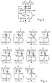
- Figure 3 shows a modified embodiment of the invention.
- the latter is designed so that two individual contact rail parts KS A and KS B are present, between which the additional fixed contact S o is located.
- the two contact rail parts KS A , KS B and the additional contact S o are fixed and fixed with respect to their relative position to one another on the driven part and are moved with it.
- the function of this embodiment is unchanged, as can be seen from the switching sequence shown in FIG. 4.
Landscapes
- Engineering & Computer Science (AREA)
- Power Engineering (AREA)
- Slide Switches (AREA)
- Types And Forms Of Lifts (AREA)
- Electrophonic Musical Instruments (AREA)
- Lock And Its Accessories (AREA)
- Elevator Control (AREA)
Description
Bei diesem bekannten Stufenschalter sind sich längs einer Bahn erstreckende feste Stufenkontakte vorgesehen, die durch einen verschiebbaren Schaltmechanismus beschaltbar sind.
Der Schaltmechanismus besteht dabei aus Aufzugsschlitten und Abtriebsteil.
Dabei ist der Aufzugsschlitten mit einem als Vorwählkontakt wirkenden mechanischen Kontakt verbunden, der mit jedem der festen Stufenkontakte in Kontakt bringbar ist und mit seinem freien Ende auf einer Kontaktschiene schleift, wobei diese wiederum über mindestens einem Überschaltwiderstand und einem ersten Vakuumschalter mit der Lastableitung in Verbindung steht.
Das Abtriebsteil ist mit einem nachlaufenden mechanischen Schaltkontakt verbunden, der ebenfalls mit jedem der festen Stufenkontakte in Verbindung bringbar ist und über einen zweiten Vakuumschalter wiederum mit der Lastableitung in Verbindung steht.
Dadurch werden insbesondere bei größeren Lastströmen hohe elektrische Anforderungen an die eingesetzten Vakuumschalter gestellt, was diese unnötig groß und teuer macht.
- Fig. 1
- zeigt eine schematische Darstellung eines ersten erfindungsgemäßen Stufenschalters
- Fig. 2
- zeigt eine entsprechende Schaltsequenz dieses Stufenschalters bei einer Umschaltung vom festen Stufenkontakt n auf den festen Stufenkontakt n+1
- Fig. 3
- zeigt eine schematische Darstellung eines zweiten erfindungsgemäßen Stufenschalters
- Fig. 4
- zeigt wiederum die entsprechende Schaltsequenz dieses Stufenschalters.
Ein zweiter mechanischer Kontakt, der Schaltkontakt SK, ist fest mit einem - hier ebenfalls nicht dargestellten - Abtriebsteil, das nach Auslösung sprungartig dem Aufzugsschlitten nachführbar ist, verbunden und mit diesem bewegbar. Er ist durch eine Reihenschaltung aus einem zweiten Vakuumschalter VS und einem dritten Vakuumschalter VL mit der Lastableitung verbunden. Statt der beschriebenen Reihenschaltung kann auch nur ein einziger Vakuumschalter in diesem Zweig vorhanden sein.
Die Kontaktschiene KS ist ebenfalls fest mit dem Abtriebsteil verbunden.
Auf dem Abtriebsteil ist ein weiterer mechanischer Kontakt So vorgesehen, der demzufolge ebenfalls mit diesem bewegbar ist. Dieser feste Kontakt So ist derart angeordnet, daß er im stationären Zustand, d.h. wenn mechanischer Hilfskontakt HK und mechanischer Schaltkontakt SK am gleichen festen Stufenkontakt n anliegen, von einer zusätzlichen Kontaktstelle HKS des Hilfskontaktes HK beschaltet ist. Dadurch ist im stationären Zustand eine direkte Verbindung vom jeweils geschalteten festen Stufenkontakt, hier n, zum festen Kontakt So und von dort, ggf. über einen weiteren Widerstand Ro zur Lastableitung unter Umgehung der Vakuumschalter VS, VL möglich. Es ist ersichtlich, daß dadurch im stationären Zustand diese Vakuumschalter von der Dauerstromführung entlastet werden.
Claims (1)
- Stufenschalter mit linearer Kontaktbetätigung, wobei feste Stufenkontakte längs einer Bahn sich in das Innere des Schalters erstrecken und durch einen verschiebbaren Schaltmechanismus beschaltbar sind,dadurch gekennzeichnet,wobei der Schaltmechanismus aus einem direkt antreibbaren Aufzugsschlitten und einem Abtriebsteil, das nach Auslösung sprungartig dem Aufzugsschlitten nachläuft, besteht,wobei der Aufzugsschlitten mit einem vorwählenden mechanischen Hilfskontakt verbunden ist, der mit jedem der festen Stufenkontakte in Kontakt bringbar ist und über mindestens einem Überschaltwiderstand und einem ersten Vakuumschalter mit der Lastableitung elektrisch in Verbindung steht,wobei das Abtriebsteil mit einem mechanischen Schaltkontakt verbunden ist, der ebenfalls mit jedem der festen Stufenkontakte in Kontakt bringbar ist und der über einen zweiten Vakuumschalter oder eine Reihenschaltung aus einem zweiten und einem dritten Vakuumschalter mit der Lastableitung elektrisch in Verbindung stehtund wobei im stationären Zustand mechanischer Hilfskontakt und mechanischer Schaltkontakt am gleichen festen Stufenkontakt anliegen,daß der vorwählende mechanische Hilfskontakt (HK) eine weitere Kontaktstelle (HKS) aufweist,daß auf dem Abtriebsteil ein zusätzlicher mechanischer fester Kontakt (So) vorgesehen ist, der direkt oder über mindestens einen weiteren Überschaltwiderstand (Ro) mit der Lastableitung (L) elektrisch in Verbindung stehtund daß im stationären Zustand die weitere Kontaktstelle (HKS) des vorwählenden mechanischen Hilfskontaktes (HK) am zusätzlichen Kontakt (So) anliegt, derart, daß dann der jeweils beschaltete feste Stufenkontakt (n, n+1) ohne Zwischenschaltung von Vakuumschaltern (VS, VL) direkt mit der Lastableitung (L) elektrisch in Verbindung steht.
Applications Claiming Priority (2)
| Application Number | Priority Date | Filing Date | Title |
|---|---|---|---|
| DE19617506 | 1996-05-02 | ||
| DE19617506A DE19617506C1 (de) | 1996-05-02 | 1996-05-02 | Stufenschalter |
Publications (3)
| Publication Number | Publication Date |
|---|---|
| EP0805464A2 EP0805464A2 (de) | 1997-11-05 |
| EP0805464A3 EP0805464A3 (de) | 1999-01-07 |
| EP0805464B1 true EP0805464B1 (de) | 2002-02-13 |
Family
ID=7793042
Family Applications (1)
| Application Number | Title | Priority Date | Filing Date |
|---|---|---|---|
| EP97105732A Expired - Lifetime EP0805464B1 (de) | 1996-05-02 | 1997-04-08 | Stufenschalter |
Country Status (3)
| Country | Link |
|---|---|
| EP (1) | EP0805464B1 (de) |
| AT (1) | ATE213357T1 (de) |
| DE (2) | DE19617506C1 (de) |
Cited By (1)
| Publication number | Priority date | Publication date | Assignee | Title |
|---|---|---|---|---|
| CN1766667B (zh) * | 2004-10-28 | 2010-04-14 | 赖茵豪森机械制造公司 | 测量负载多点开关上开关时间的方法和开关时间测量电路 |
Family Cites Families (4)
| Publication number | Priority date | Publication date | Assignee | Title |
|---|---|---|---|---|
| SE394920B (sv) * | 1975-10-29 | 1977-07-18 | Asea Ab | Lindningskopplare |
| DE4237165C1 (de) * | 1992-11-04 | 1994-03-17 | Reinhausen Maschf Scheubeck | Einpoliger Stufenschalter mit linearer Kontaktbetätigung für einen Stufentransformator |
| DE4315081A1 (de) * | 1992-11-04 | 1994-11-10 | Reinhausen Maschf Scheubeck | Einpoliger Stufenschalter mit linearer Kontaktbetätigung |
| DE4407945C1 (de) * | 1994-03-09 | 1995-10-12 | Reinhausen Maschf Scheubeck | Umschaltanordnung für Lastumschalter und für Lastwähler |
-
1996
- 1996-05-02 DE DE19617506A patent/DE19617506C1/de not_active Expired - Fee Related
-
1997
- 1997-04-08 AT AT97105732T patent/ATE213357T1/de not_active IP Right Cessation
- 1997-04-08 EP EP97105732A patent/EP0805464B1/de not_active Expired - Lifetime
- 1997-04-08 DE DE59706355T patent/DE59706355D1/de not_active Expired - Fee Related
Cited By (1)
| Publication number | Priority date | Publication date | Assignee | Title |
|---|---|---|---|---|
| CN1766667B (zh) * | 2004-10-28 | 2010-04-14 | 赖茵豪森机械制造公司 | 测量负载多点开关上开关时间的方法和开关时间测量电路 |
Also Published As
| Publication number | Publication date |
|---|---|
| DE59706355D1 (de) | 2002-03-21 |
| DE19617506C1 (de) | 1997-11-27 |
| EP0805464A2 (de) | 1997-11-05 |
| EP0805464A3 (de) | 1999-01-07 |
| ATE213357T1 (de) | 2002-02-15 |
Similar Documents
| Publication | Publication Date | Title |
|---|---|---|
| EP3427284B1 (de) | Laststufenschalter | |
| EP0650637B1 (de) | Stufenschalter | |
| EP2539909B1 (de) | Stufenschalter | |
| EP3970172B1 (de) | Laststufenschalter | |
| EP0907193B1 (de) | Stufenschalter | |
| DE102009017197A1 (de) | Stufenschalter mit Halbleiter-Schaltelementen | |
| DE3619587C2 (de) | ||
| DE4407945C1 (de) | Umschaltanordnung für Lastumschalter und für Lastwähler | |
| DE4237165C1 (de) | Einpoliger Stufenschalter mit linearer Kontaktbetätigung für einen Stufentransformator | |
| DE102006030030A1 (de) | Elektrische Werkzeugmaschine und Schalter dafür | |
| EP0805464B1 (de) | Stufenschalter | |
| DE1005596B (de) | Haengeschalter fuer Einhandbedienung von Hub- und Fahrwerksmotoren | |
| EP0158995B1 (de) | Spannungszuführung | |
| DE4317656C2 (de) | Schaltschütz mit Hilfsschalter | |
| DE3000748C2 (de) | Stufenschalter für einen dreiphasigen Transformator mit sternförmig zusammengeschalteten Vakuumschaltern | |
| DE2355514C3 (de) | Lastumschalter für Transformatoren | |
| EP4200886B1 (de) | Laststufenschalter und verfahren zur betätigung eines laststufenschalters | |
| EP4226403A1 (de) | Laststufenschalter und verfahren zur betätigung eines laststufenschalters | |
| DE722544C (de) | Einhub-Fusshebelsteuerung fuer elektrisch angetriebene Fahrzeuge, insbesondere fuer Oberleitungsomnibusse | |
| DE29818195U1 (de) | Schalter zur wahlweisen Parallel- oder Reihenschaltung | |
| DE4315081A1 (de) | Einpoliger Stufenschalter mit linearer Kontaktbetätigung | |
| DE2163239B2 (de) | Elektrische Schaltervorrichtung, insbesondere zum Steuern eines Zentralheizu ngssystems | |
| DE2125199A1 (de) | Drucktastenschalter, insbesondere für Kraftfahrzeuge | |
| DE3204915A1 (de) | Selbstschalter, insbesondere fernmeldeschutzschalter und verfahren zum montieren und justieren | |
| DE3544351A1 (de) | Einbauschaltvorrichtung, insbesondere fuer handbohrmaschinen |
Legal Events
| Date | Code | Title | Description |
|---|---|---|---|
| PUAI | Public reference made under article 153(3) epc to a published international application that has entered the european phase |
Free format text: ORIGINAL CODE: 0009012 |
|
| AK | Designated contracting states |
Kind code of ref document: A2 Designated state(s): AT DE GB SE |
|
| PUAL | Search report despatched |
Free format text: ORIGINAL CODE: 0009013 |
|
| AK | Designated contracting states |
Kind code of ref document: A3 Designated state(s): AT DE GB SE |
|
| 17P | Request for examination filed |
Effective date: 19990122 |
|
| GRAG | Despatch of communication of intention to grant |
Free format text: ORIGINAL CODE: EPIDOS AGRA |
|
| GRAG | Despatch of communication of intention to grant |
Free format text: ORIGINAL CODE: EPIDOS AGRA |
|
| GRAH | Despatch of communication of intention to grant a patent |
Free format text: ORIGINAL CODE: EPIDOS IGRA |
|
| 17Q | First examination report despatched |
Effective date: 20010719 |
|
| GRAH | Despatch of communication of intention to grant a patent |
Free format text: ORIGINAL CODE: EPIDOS IGRA |
|
| GRAA | (expected) grant |
Free format text: ORIGINAL CODE: 0009210 |
|
| REG | Reference to a national code |
Ref country code: GB Ref legal event code: IF02 |
|
| AK | Designated contracting states |
Kind code of ref document: B1 Designated state(s): AT DE GB SE |
|
| REF | Corresponds to: |
Ref document number: 213357 Country of ref document: AT Date of ref document: 20020215 Kind code of ref document: T |
|
| GBT | Gb: translation of ep patent filed (gb section 77(6)(a)/1977) |
Effective date: 20020215 |
|
| REF | Corresponds to: |
Ref document number: 59706355 Country of ref document: DE Date of ref document: 20020321 |
|
| PLBE | No opposition filed within time limit |
Free format text: ORIGINAL CODE: 0009261 |
|
| STAA | Information on the status of an ep patent application or granted ep patent |
Free format text: STATUS: NO OPPOSITION FILED WITHIN TIME LIMIT |
|
| 26N | No opposition filed |
Effective date: 20021114 |
|
| PGFP | Annual fee paid to national office [announced via postgrant information from national office to epo] |
Ref country code: AT Payment date: 20040401 Year of fee payment: 8 |
|
| PGFP | Annual fee paid to national office [announced via postgrant information from national office to epo] |
Ref country code: GB Payment date: 20040402 Year of fee payment: 8 |
|
| PGFP | Annual fee paid to national office [announced via postgrant information from national office to epo] |
Ref country code: DE Payment date: 20050302 Year of fee payment: 9 |
|
| PG25 | Lapsed in a contracting state [announced via postgrant information from national office to epo] |
Ref country code: GB Free format text: LAPSE BECAUSE OF NON-PAYMENT OF DUE FEES Effective date: 20050408 Ref country code: AT Free format text: LAPSE BECAUSE OF NON-PAYMENT OF DUE FEES Effective date: 20050408 |
|
| PGFP | Annual fee paid to national office [announced via postgrant information from national office to epo] |
Ref country code: SE Payment date: 20050415 Year of fee payment: 9 |
|
| GBPC | Gb: european patent ceased through non-payment of renewal fee |
Effective date: 20050408 |
|
| PG25 | Lapsed in a contracting state [announced via postgrant information from national office to epo] |
Ref country code: SE Free format text: LAPSE BECAUSE OF NON-PAYMENT OF DUE FEES Effective date: 20060409 |
|
| PG25 | Lapsed in a contracting state [announced via postgrant information from national office to epo] |
Ref country code: DE Free format text: LAPSE BECAUSE OF NON-PAYMENT OF DUE FEES Effective date: 20061101 |
|
| EUG | Se: european patent has lapsed |