EP0805411A2 - Reconnaissance d'images avec seuil de binarisation déterminé par soustraction d'image - Google Patents
Reconnaissance d'images avec seuil de binarisation déterminé par soustraction d'image Download PDFInfo
- Publication number
- EP0805411A2 EP0805411A2 EP97107025A EP97107025A EP0805411A2 EP 0805411 A2 EP0805411 A2 EP 0805411A2 EP 97107025 A EP97107025 A EP 97107025A EP 97107025 A EP97107025 A EP 97107025A EP 0805411 A2 EP0805411 A2 EP 0805411A2
- Authority
- EP
- European Patent Office
- Prior art keywords
- image
- threshold
- difference
- positive
- negative
- Prior art date
- Legal status (The legal status is an assumption and is not a legal conclusion. Google has not performed a legal analysis and makes no representation as to the accuracy of the status listed.)
- Withdrawn
Links
Images


Classifications
-
- G—PHYSICS
- G06—COMPUTING; CALCULATING OR COUNTING
- G06V—IMAGE OR VIDEO RECOGNITION OR UNDERSTANDING
- G06V10/00—Arrangements for image or video recognition or understanding
- G06V10/20—Image preprocessing
- G06V10/28—Quantising the image, e.g. histogram thresholding for discrimination between background and foreground patterns
Definitions
- the present invention relates to an image recognition device used in the control of unmanned transport cars, depalletizers, picking robots, machining centers and the like and more specifically relates to an image recognition device which recognizes a target article using a threshold image in converting an image photographed using a slit pattern into binary.
- a depalletizer, a picking robot or the like handles an article to be transported or picked, for example the work, while it is recognizing the target article by an associated image recognition device.
- the image recognition device uses a space code image. Specifically, the image recognition device illuminates the target article by a projector while changing a slit pattern, takes a picture of the light reflected from the upper surface of the article by a CCD camera or the like and converts this image into a space code image in binary. The obtained space code image is then image processed and the shape of the work is determined.
- a threshold image is necessary for binary conversion.
- the inventor noted the following in this conversion process.
- Fig.7A of the accompanying drawings it should be supposed that the work W is illuminated from the direction of the arrows R and the reflected light R' is photographed. Taking the v-v direction as the direction in which the space will be coded, the brightness of the positive image P and negative image N (the negative image is the image photographed by reversing the slit pattern with the same resolution) along this direction is illustrated in Fig.7B.
- Each of the positive and negative images P and N slight declines as the v increases because the reflected light R' becomes weaker or darker as the distance between the projector and the illuminated part of the work W increases.
- a threshold image is to photograph the positive and negative images of a work-loading plane while there is no work W on it and to calculate an average image, and this average image is used as the threshold (as indicated by the single-dot chain line in Fig.7B). Then, conversion of the positive image to binary is carried out by allocating pixels brighter than the threshold a 1 and pixels darker a 0.
- a threshold image is obtained using the work W itself, only part of the threshold image can be utilized.
- the negative image N is taken as the threshold image and image recognition is carried out using the difference between this threshold and the positive image P, in short the difference P - N.
- the brightness of the difference image (P - N) in the area of pattern A also becomes too small and mistaken recognition occurs again.
- Another approach is shown in Fig.7D.
- the average value of the positive image P and negative image N ( 1/2(P+N) ) is taken as the threshold image.
- the threshold value is the middle value between the positive image P and negative image N, an error would be included in the binary image if noise of more than 1/2 the difference (or amplitude) between the positive image and negative image is generated during image recognition.
- Another object of the present invention is to propose an image recognition device that does not require operations producing the threshold image beforehand.
- Still another object of the present invention is to provide an image recognition device which reduces the amount of calculation in order to determine the threshold image.
- a yet another object of the invention is to provide an image recognition device which reduces noise generated in the space code image.
- Another object of the invention is to provide an image recognition device which reduces the amount of data processing required for generation of the threshold image and the memory required for storage of these data.
- an image recognition device comprising: means for preparing a plurality of positive and negative images of a target article using a plurality of slit light patterns respectively; means for preparing a threshold image from a combination of first and second difference images for each slit pattern, the first difference image obtained by subtracting a negative image from a positive image of the target article and the second difference image obtained by subtracting the positive image from the negative image for the each slit light pattern; means for comparing the threshold image with the first or second difference image for the each slit light pattern; and means for producing a space code image of the article based on comparison results.
- the number of slit patterns SPN in short, the bit width of the resolution of the space code image may be from, for example, 2 to 24, and preferably from 4 to 12. It should be noted that the slit pattern is not limited to a simple binary pattern and may be a gray coded pattern.
- the decision of whether which of a pair of slit patterns of the same resolution is the positive and which is the negative and similarly which of a pair of images is the positive image and which is the negative image is a relative rule and has no particular relevance.
- combination or synthesis of images means that a single image cannot determine a ultimate image but two image can only determine it.
- the ultimate image is of course a function of these two images.
- image data for a monochrome image is larger the brighter the image, and for color images, is defined along each axis such as R, G, B and is larger the brighter with respect to a single axis.
- the size of the image data may occasionally have a complementary relationship with the size of the data in the actual memory such as the frame memory or the like in this specification.
- image data means data from every pixel but it may represent collective or average data from a plurality of pixels in a particular area.
- the threshold image is determined by the both the subtraction of the negative image from the positive image and the positive image from the negative image, the threshold is reduced in the area of the pattern A of Fig.7B and therefore it is feasible to correctly convert the photographed image to binary even if the reflectance of the article surface is not uniform. Also, the influence of a light not originated from a light projector of the image recognition device is removed in the courser of subtraction between the positive and negative images and does not arise in the threshold image and the difference image of the object converted to binary.
- the threshold preparation means includes maximum value calculation means for determining whether the first difference image is greater than the second difference image.
- the threshold image may be produced using the maximum value of two difference images.
- the maximum value may be calculated by comparisons of two images at each pixel or by smoothing the data in the range of a plurality of pixels before comparison and comparing them in the form of unit larger than one pixel. In either case, a necessary processing is comparison of two values and selection of a larger one. It is unnecessary to calculate an average value or the like. Accordingly, the amount of processing for preparation of the threshold value is minimized.
- the maximum value does not need to be the threshold value and it is preferable, in consideration of a detection margin, to remove the noise from the maximum value after smoothing or to subtract a certain value from the maximum value.
- a single threshold image is prepared using a slit light pattern of a greatest resolution and this threshold image is utilized for comparison for all of the slit light patterns. If only a single threshold image is needed, the memory capacity necessary for memorization and data processing necessary for the production of the threshold image is reduced.
- the slit pattern of the greatest resolution is the one having the most complicated slit pattern.
- the amplitude between the positive and negative images, in short, the absolute values of the difference between them is reduced when the space coding resolution increases as shown in Fig.6B (the space coding resolution increases from 2 0 pattern to 2 8 pattern).
- the threshold image is originally slightly darker than the images photographed using lower resolution slit patterns, i.e., the threshold image is never brighter excessively.
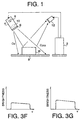
- Figure 1 illustrates the arrangement of the image recognition device according to the present invention.
- Figure 2 illustrates a schematic view of the construction of the image recognition device shown in Fig.1.
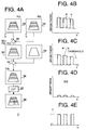
- FIGS 3A through 3E illustrate production of the threshold image according to the present invention.
- FIGS 3F and 3G illustrate another examples of threshold image, respectively.
- Figures 4A through 4E show production of the space code image.
- FIGS 5A through 5C illustrate the positive and negative images of the present invention.
- Figures 6A and 6B illustrate the amplitudes of the positive and negative images produced in particular patterns.
- Figures 7A through 7E illustrate production of the threshold image by a conventional device and method.
- Figs. 1 through 6 show an embodiment of the present invention.
- Fig.1 illustrates the arrangement of the image recognition device with W being a work (i.e., object or target article) to be recognized positioned on a pallet B for example.
- a reference numeral 2 designates an image recognition device provided with a projector 4.
- the projector 4 includes a liquid crystal shutter array 6, light source 8 and lens 10.
- the projector 4 may be any type of conventional projectors as long as it is able to illuminate the object and change the slit pattern (hereafter, simply referred to as "pattern").
- a reference numeral 12 designates a CCD camera in this particular embodiment but any suitable camera other than a CCD camera may be equally used.
- the illumination space defined by the projector 4 is divided into, for example, space segments C0 - C255, each of which having a 8-bit width.
- the reflected light is received by the camera 12 and allotted a space code value of 0 to 255 with respect to the upper surface of the work W.
- the image recognition device determines the position of the work W from the space code image and then a depalletizer or the like (not shown) picks up the work.
- FIG.2 illustrates the construction of the image recognition device 2 of the present embodiment.
- a reference numeral 20 designates a projector control which controls the liquid crystal shutter array 6 and light source 8 of the projector 4.
- a reference numeral 22 designates a control for the camera 12.
- a switch 24 is arranged at the output of the camera control 22 so that it is possible to exchange the image data input destination between a positive image side and a negative image side by a signal from the projector control unit 20.
- Reference numerals 26, 28, 30, 32, 34, 36 and 38 are one group of frame memories, each having for example an 8 bit data width, and are arranged with only the necessary pieces. It should be noted that as far as no errors and inconsistency are generated in data processing, a single piece of frame memory may be used for a plurality of purposes or some of the illustrated frame memories may be omitted.
- Reference numerals 40, 42 and 44 designate difference calculators respectively and are examples of the subtraction means.
- a reference numeral 46 designates a maximum value calculation unit which compares two difference images provided from the two frame memories 30 and 32 and outputs the larger value of data for each pixel.
- a reference numeral 48 designates a smoothing unit which smooths the output from the maximum value calculation unit 46 using a filter of such as 3x3 to 5x5 type or the like.
- a reference numeral 50 designates a subtraction unit which subtracts, for example, 2 to 3 bits from the threshold upon the output of the smoothing unit 48.
- the maximum value calculation unit 46, smoothing unit 48 and subtraction unit 50 constitute in combination the synthesis means.
- the post-processed data is memorized in the frame memory 34 as data for each pixel of the threshold image.
- the threshold image is subtracted from the difference image S(i) of the positive image P(i) and negative image N(i) obtained in case of the slit pattern No. i and the resulting difference image D(i) is memorized in the frame memory 36.
- the pixel value of this image is compared to the value in the look-up table or LUT 52 and a "1" is output for pixels higher than this value and a "0" is output for pixels less. This forms the value of the i'th bit plane of the space code image. In this way, a space code image of 8 bit width is produced.
- Figs.3A to 3E illustrate the process of production of the threshold image.
- This series of drawings depicts the structure of the image recognition device of Fig.2 in relation to the production of the threshold image.
- Fig.3A illustrates the flow of image data between the frame memories 26 to 34.
- the image of the upper surface of the work as photographed is only illustrated in Fig.3A.
- the shaded areas in the image represent darker areas of the work upper surface and the unshaded areas represent brighter areas as a result of slit light projection.
- the image in the chain-line square between the maximum value calculation unit 46 and smoothing unit 48 shows the pre-smoothing image (a frame memory is not assigned to this image in the present embodiment).
- Each image uses the direction where coding of the space by the slit is performed as the v direction and the direction vertical to this as the u direction with the upper left corner of the frame memory as the home position.
- An image of the work W is only shown in each frame memory and the peripheral background image has been omitted. It should be noted that as the space code value for the upper surface of the work W and peripheral background are different, it is simple to remove the peripheral background image from the obtained space code image.
- the slit pattern is converted into 9 different types (patterns 2 0 to 2 8 : in actuality, 18 types are given by the inversion of positive and negative). 8 positive image photographs are taken for each slit pattern as well as 8 negative image photographs for the pattern that inverses the just used slit pattern in this particular embodiment.
- the slit pattern may be a pure or simple binary pattern or a gray code pattern. A gray code pattern is used in the present embodiment.
- 8 positive images are memorized in the frame memory 26 and 8 negative images are memorized in the frame memory 28 as illustrated in Fig.3A.
- a positive image P(8) and negative image N(8) (the figure 8 expresses the type of slit pattern) are used in the production of the threshold image. These are images photographed using the slit pattern with the highest space resolution.
- the brightness distributions along the v direction of the positive image P(8) and negative image N(8) are respectively illustrated in Fig.3B.
- the negative image N(8) is subtracted from the positive image P(8) in the subtracting device 40 to form the difference image S(8) as illustrated in Fig.3A.
- the positive image P(8) is subtracted from the negative image N(8) in the subtracting device 42 to form the difference image T(8).
- the maximum values of the two difference images are determined in the maximum value calculation unit 46. More specifically, the data of each pixel in the frame memories 30 and 32 are compared with each other in the unit 46 and the larger data is output therefrom. In the current specification, if the light entering the CCD camera is zero, then "0" is assigned to the pixel, and if the entering light is the maximum, then the value 255 is assigned. The resulting image is illustrated in Fig.3D. The image obtained by subtracting the negative image from the positive image and the image obtained by subtracting the positive image from the negative image are not those having opposite signs and the same absolute value.
- the pixel takes the value 0.
- the pixel also takes the value 0.
- the symbol "Max” in Fig.3D represents a function for outputting the larger of the input data (P-N) and (N-P). Accordingly, the image P-N and the image N-P become both darker with respect to the pattern A on the work W (Fig.7A) and the threshold is correspondingly reduced in the area of the pattern A. In other words, the threshold with respect to the part with a low reflectance naturally decreases and the threshold with respect to the bright part with a high reflectance naturally increases. The influence of incoming light other than that from the projector 4 has already been removed when the positive image is subtracted from the negative image and vice versa.
- the basic data for the threshold image can be obtained by a simple comparison.
- the average value of the image P-N and image N-P may be used. In this case, an averaging operation is necessary so that the total amount of calculation in preparation of the threshold value increases.
- the threshold value obtained by this method appears is half in amplitude as shown in Fig.3F, as compared with that shown in Fig.3D. Due to this, if noise of over 1/2 the amplitude of between positive image P and negative image N is added to those parts to which no slit light is illuminated, a noise is included in image recognition.
- an equation such as: 3/4 x Max (P-N, N-P) + 1/4 x Min (P-N, N-P) may be used on the threshold.
- "Min” represents a function for outputting the smaller of the two image data
- "Max” represents a function for outputting the larger of the two image data.
- the threshold has about the 3/4 the amplitude of the one shown in Fig.3D, as illustrated in Fig.3G.
- this processing is inferior to the processing using Max (P-N, N-P) as the calculation is more complicated. Accordingly it is preferable to use Max(P-N, N-P) in acquiring the basic data for the threshold image.
- Noise as shown in Fig.3D remains in the output of the maximum value calculation unit 46. This is thus smoothed by the smoothing unit 48 using a filter such as a 3 x 3 or 5 x 5 type. After that, the post-smoothed data is subtracted, for example, 2 to 3 bits. This produces a threshold image slightly darker than the difference image S obtained by subtracting the negative image N from the positive image P. This is memorized in the frame memory 34 and is illustrated in Fig.3E.
- Fig.5A through Fig.6B show the properties of the threshold image.
- Fig.5A illustrates the upper surface of the work as well as its front face.
- Fig.5B illustrates the brightness distributions of the positive image P and negative image N in the v-v direction and
- Fig.5C illustrates those in the u-u direction.
- the curve of the negative image N in the center area protrudes from the curve of the positive image P in the other areas since the work exists in the center area.
- the protruding negative image curve represents the width of the work or "range of article".
- each threshold image has a slightly smaller amplitude than the amplitude of the positive image P and negative image N.
- the threshold In an area where the amplitude between the positive and negative images P and N is smaller such as the pattern A on the work W (Fig.7A), the threshold automatically becomes smaller and in an area of larger amplitude the threshold automatically becomes larger. In this manner, the threshold always takes an appropriate value.
- threshold images may be prepared for nine slit patterns, respectively. However, doing this increases the amount of data processing for preparation of the threshold images and increases the memory capacity of the threshold images as nine times as much.
- Figs.6A and 6B The way the positive and negative images change their forms due to the change in slit pattern along the space coded direction (v direction) is shown in Figs.6A and 6B.
- the brightness of the positive image draws the line as indicated by the solid straight line in Fig.6B.
- the brightness of the positive image draws a stepwise curve as indicated by the broken line in Fig.6B.
- the amplitude between the positive and negative images decreases and the base brightness increases (the base brightness of the pattern 2 1 is indicated by the double arrow in Fig.6B). This is due to the fact that the light from the projector 4 also reaches areas shielded from the slit light as each of the slits becomes narrower, and the brightness at a position illuminated by the slit light decreases.
- the threshold image is produced using the slit pattern of the greatest space resolution (pattern 2 8 of Fig.6B), which is the case of the present embodiment, this image has a smaller amplitude than any of the slit patterns 2 0 to 2 7 (i.e., the former is darker than the latter) and therefore can be used as the threshold image.
- a threshold image is produced using a slit pattern of space resolution other than 2 8 and applied to all of the slit patterns, the threshold exceeds the amplitude of between the positive image and negative image in certain cases. In consideration of this, when only one threshold image is taken, it should be the one obtained from the two images photographed using the slit pattern of the greatest space resolution (i.e., 2 8 pattern).
- Figs.4A to 4E illustrate the processing of after obtaining the threshold image.
- the negative image N(i) is subtracted from the positive image P(i) in the subtracting device 40 for each of Nos. 1 to 8 images and the difference images S(i) are memorized in the frame memory 30 (Fig.4C).
- the threshold image is subtracted from each difference image in the subtracter 44 (D(i)), and the resulting images are stored in the frame memory 36 (Fig.4D).
- a space code image may be obtained, the shape of the upper surface of the work W is determined, and the work W may be transported by a depalletizer or the like based on this.
Applications Claiming Priority (3)
| Application Number | Priority Date | Filing Date | Title |
|---|---|---|---|
| JP134256/96 | 1996-04-30 | ||
| JP13425696 | 1996-04-30 | ||
| JP8134256A JP2921748B2 (ja) | 1996-04-30 | 1996-04-30 | 画像認識装置 |
Publications (2)
| Publication Number | Publication Date |
|---|---|
| EP0805411A2 true EP0805411A2 (fr) | 1997-11-05 |
| EP0805411A3 EP0805411A3 (fr) | 1999-09-15 |
Family
ID=15124054
Family Applications (1)
| Application Number | Title | Priority Date | Filing Date |
|---|---|---|---|
| EP97107025A Withdrawn EP0805411A3 (fr) | 1996-04-30 | 1997-04-28 | Reconnaissance d'images avec seuil de binarisation déterminé par soustraction d'image |
Country Status (2)
| Country | Link |
|---|---|
| EP (1) | EP0805411A3 (fr) |
| JP (1) | JP2921748B2 (fr) |
Cited By (2)
| Publication number | Priority date | Publication date | Assignee | Title |
|---|---|---|---|---|
| EP1706839A2 (fr) * | 2004-01-15 | 2006-10-04 | Technion Research & Development Foundation Limited | Dispositif de balayage video tridimensionnel |
| EP2169629A3 (fr) * | 2008-09-17 | 2011-01-19 | Kabushiki Kaisha Toshiba | Appareil de traitement de reconnaissance d'informations et procédé de traitement de reconnaissance d'informations |
Families Citing this family (5)
| Publication number | Priority date | Publication date | Assignee | Title |
|---|---|---|---|---|
| JP4556555B2 (ja) * | 2004-08-25 | 2010-10-06 | 富士ゼロックス株式会社 | 三次元画像取得装置および方法 |
| JP2006098252A (ja) * | 2004-09-30 | 2006-04-13 | Brother Ind Ltd | 3次元情報取得方法 |
| JP5016520B2 (ja) * | 2008-02-26 | 2012-09-05 | パナソニック株式会社 | 3次元形状計測方法および装置 |
| JP6041790B2 (ja) * | 2013-11-22 | 2016-12-14 | 本田技研工業株式会社 | コイル間隙測定方法 |
| JP7202966B2 (ja) * | 2019-04-26 | 2023-01-12 | 株式会社キーエンス | 三次元測定装置及び三次元測定方法 |
Citations (2)
| Publication number | Priority date | Publication date | Assignee | Title |
|---|---|---|---|---|
| DE3128927A1 (de) * | 1981-07-22 | 1983-06-01 | Dornier Gmbh, 7990 Friedrichshafen | Verfahren und vorrichtung zur bildmustererkennung |
| JPH05344427A (ja) * | 1992-06-08 | 1993-12-24 | Asahi Optical Co Ltd | 撮像装置 |
-
1996
- 1996-04-30 JP JP8134256A patent/JP2921748B2/ja not_active Expired - Fee Related
-
1997
- 1997-04-28 EP EP97107025A patent/EP0805411A3/fr not_active Withdrawn
Patent Citations (2)
| Publication number | Priority date | Publication date | Assignee | Title |
|---|---|---|---|---|
| DE3128927A1 (de) * | 1981-07-22 | 1983-06-01 | Dornier Gmbh, 7990 Friedrichshafen | Verfahren und vorrichtung zur bildmustererkennung |
| JPH05344427A (ja) * | 1992-06-08 | 1993-12-24 | Asahi Optical Co Ltd | 撮像装置 |
Non-Patent Citations (2)
| Title |
|---|
| FORMAN A V JR ET AL: "Robot vision system for depalletizing steel cylindrical billets" OPTICAL ENGINEERING, MARCH 1986, USA, vol. 25, no. 3, pages 402-408, XP002108949 ISSN: 0091-3286 * |
| PATENT ABSTRACTS OF JAPAN vol. 018, no. 180 (E-1531), 28 March 1994 (1994-03-28) & JP 05 344427 A (ASAHI OPTICAL CO LTD), 24 December 1993 (1993-12-24) * |
Cited By (5)
| Publication number | Priority date | Publication date | Assignee | Title |
|---|---|---|---|---|
| EP1706839A2 (fr) * | 2004-01-15 | 2006-10-04 | Technion Research & Development Foundation Limited | Dispositif de balayage video tridimensionnel |
| EP1706839B1 (fr) * | 2004-01-15 | 2014-11-12 | Technion Research & Development Foundation Limited | Dispositif de balayage video tridimensionnel |
| EP2169629A3 (fr) * | 2008-09-17 | 2011-01-19 | Kabushiki Kaisha Toshiba | Appareil de traitement de reconnaissance d'informations et procédé de traitement de reconnaissance d'informations |
| KR101012920B1 (ko) | 2008-09-17 | 2011-02-08 | 가부시끼가이샤 도시바 | 정보 인식 처리 장치 및 정보 인식 처리 방법 |
| US8033470B2 (en) | 2008-09-17 | 2011-10-11 | Kabushiki Kaisha Toshiba | Information recognition processing apparatus and information recognition processing method |
Also Published As
| Publication number | Publication date |
|---|---|
| JP2921748B2 (ja) | 1999-07-19 |
| JPH09297846A (ja) | 1997-11-18 |
| EP0805411A3 (fr) | 1999-09-15 |
Similar Documents
| Publication | Publication Date | Title |
|---|---|---|
| KR960008379B1 (ko) | 다수의 휘도준위를 갖는 화상의 이진화 처리방법 | |
| US5375197A (en) | System and method for automatically distinguishing between graphic information and text information of image data | |
| US7764835B2 (en) | Method and apparatus for recognizing code | |
| US6047893A (en) | Method of locating an object-applied optical code | |
| US6332574B1 (en) | Method of reading bar code | |
| US5371610A (en) | Image data processing apparatus | |
| EP0805411A2 (fr) | Reconnaissance d'images avec seuil de binarisation déterminé par soustraction d'image | |
| US5068908A (en) | Method and apparatus for detecting mark from image data | |
| US7239758B2 (en) | Signal processing device for reducing noise of image signal, signal processing program, and signal processing method | |
| EP0586708B1 (fr) | Dispositif de traitement d'images et procede associe | |
| EP0392460B1 (fr) | Balayeur d'image en relief | |
| EP0719032A2 (fr) | Méthode et dispositif pour lire une image | |
| US5805723A (en) | Image processing apparatus with means for adjusting image data for divided areas | |
| US20070009173A1 (en) | Apparatus and method for shading correction and recording medium therefore | |
| JP3906221B2 (ja) | 画像処理方法及び画像処理装置 | |
| JP4728297B2 (ja) | 2次元コード読取装置及びその方法 | |
| CN115270839A (zh) | 一种基于PPYOLOv2模型的工业场景QR Code检测与识别方法 | |
| JP2019067389A (ja) | カードリーダおよびカードリーダの制御方法 | |
| US6995802B2 (en) | Image binarization method and binary image creation method | |
| JPH11175655A (ja) | 車番読取装置 | |
| JPH04233402A (ja) | テレビカメラによる対象物の位置認識方式 | |
| JPH09307765A (ja) | 画像処理方法および装置 | |
| JPH0946516A (ja) | 画像処理装置 | |
| JP3679453B2 (ja) | 画像処理装置及びその画像処理方法 | |
| JPS63308471A (ja) | 画像信号二値化装置 |
Legal Events
| Date | Code | Title | Description |
|---|---|---|---|
| PUAI | Public reference made under article 153(3) epc to a published international application that has entered the european phase |
Free format text: ORIGINAL CODE: 0009012 |
|
| AK | Designated contracting states |
Kind code of ref document: A2 Designated state(s): DE FR GB IT SE |
|
| PUAL | Search report despatched |
Free format text: ORIGINAL CODE: 0009013 |
|
| AK | Designated contracting states |
Kind code of ref document: A3 Designated state(s): DE FR GB IT SE |
|
| 17P | Request for examination filed |
Effective date: 19991209 |
|
| GRAG | Despatch of communication of intention to grant |
Free format text: ORIGINAL CODE: EPIDOS AGRA |
|
| RIC1 | Information provided on ipc code assigned before grant |
Free format text: 7G 06K 9/38 A, 7G 06K 9/20 B, 7G 06T 7/00 B |
|
| RTI1 | Title (correction) |
Free format text: IMAGE RECOGNITION WHEREBY THE BINARIZATION THRESHOLD IS DETERMINED BY DOUBLE IMAGE SUBSTRACTION |
|
| 17Q | First examination report despatched |
Effective date: 20020617 |
|
| STAA | Information on the status of an ep patent application or granted ep patent |
Free format text: STATUS: THE APPLICATION HAS BEEN WITHDRAWN |
|
| 18W | Application withdrawn |
Withdrawal date: 20021014 |