EP0805230A2 - Ink-jet printing process and print - Google Patents
Ink-jet printing process and print Download PDFInfo
- Publication number
- EP0805230A2 EP0805230A2 EP97106845A EP97106845A EP0805230A2 EP 0805230 A2 EP0805230 A2 EP 0805230A2 EP 97106845 A EP97106845 A EP 97106845A EP 97106845 A EP97106845 A EP 97106845A EP 0805230 A2 EP0805230 A2 EP 0805230A2
- Authority
- EP
- European Patent Office
- Prior art keywords
- ink
- dye
- inks
- jet printing
- printing process
- Prior art date
- Legal status (The legal status is an assumption and is not a legal conclusion. Google has not performed a legal analysis and makes no representation as to the accuracy of the status listed.)
- Granted
Links
Images
Classifications
-
- D—TEXTILES; PAPER
- D06—TREATMENT OF TEXTILES OR THE LIKE; LAUNDERING; FLEXIBLE MATERIALS NOT OTHERWISE PROVIDED FOR
- D06P—DYEING OR PRINTING TEXTILES; DYEING LEATHER, FURS OR SOLID MACROMOLECULAR SUBSTANCES IN ANY FORM
- D06P5/00—Other features in dyeing or printing textiles, or dyeing leather, furs, or solid macromolecular substances in any form
- D06P5/30—Ink jet printing
-
- B—PERFORMING OPERATIONS; TRANSPORTING
- B41—PRINTING; LINING MACHINES; TYPEWRITERS; STAMPS
- B41M—PRINTING, DUPLICATING, MARKING, OR COPYING PROCESSES; COLOUR PRINTING
- B41M5/00—Duplicating or marking methods; Sheet materials for use therein
-
- D—TEXTILES; PAPER
- D06—TREATMENT OF TEXTILES OR THE LIKE; LAUNDERING; FLEXIBLE MATERIALS NOT OTHERWISE PROVIDED FOR
- D06P—DYEING OR PRINTING TEXTILES; DYEING LEATHER, FURS OR SOLID MACROMOLECULAR SUBSTANCES IN ANY FORM
- D06P5/00—Other features in dyeing or printing textiles, or dyeing leather, furs, or solid macromolecular substances in any form
- D06P5/20—Physical treatments affecting dyeing, e.g. ultrasonic or electric
- D06P5/2066—Thermic treatments of textile materials
- D06P5/2077—Thermic treatments of textile materials after dyeing
-
- D—TEXTILES; PAPER
- D06—TREATMENT OF TEXTILES OR THE LIKE; LAUNDERING; FLEXIBLE MATERIALS NOT OTHERWISE PROVIDED FOR
- D06P—DYEING OR PRINTING TEXTILES; DYEING LEATHER, FURS OR SOLID MACROMOLECULAR SUBSTANCES IN ANY FORM
- D06P1/00—General processes of dyeing or printing textiles, or general processes of dyeing leather, furs, or solid macromolecular substances in any form, classified according to the dyes, pigments, or auxiliary substances employed
- D06P1/16—General processes of dyeing or printing textiles, or general processes of dyeing leather, furs, or solid macromolecular substances in any form, classified according to the dyes, pigments, or auxiliary substances employed using dispersed, e.g. acetate, dyestuffs
-
- D—TEXTILES; PAPER
- D06—TREATMENT OF TEXTILES OR THE LIKE; LAUNDERING; FLEXIBLE MATERIALS NOT OTHERWISE PROVIDED FOR
- D06P—DYEING OR PRINTING TEXTILES; DYEING LEATHER, FURS OR SOLID MACROMOLECULAR SUBSTANCES IN ANY FORM
- D06P3/00—Special processes of dyeing or printing textiles, or dyeing leather, furs, or solid macromolecular substances in any form, classified according to the material treated
- D06P3/34—Material containing ester groups
- D06P3/52—Polyesters
- D06P3/54—Polyesters using dispersed dyestuffs
Definitions
- the present invention relates to an ink-jet printing process wherein printing is conducted on a cloth by ink-jet system to provide a print having excellent gradation and high saturation, and to a printed article obtained by such a process.
- Requirements of the textile printing processes according to an ink-jet system include:
- an ink-jet printing process comprising the three steps of:
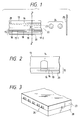
- Fig. 1 is a longitudinal cross-sectional view of a head of an ink-jet printing apparatus.
- Fig. 2 is a transverse cross-sectional view of the head of the ink-jet printing apparatus.
- Fig. 3 is a perspective view of the appearance of a multi-head which is an array of such heads as shown in Fig. 1.
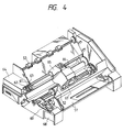
- Fig. 4 is a perspective view of an illustrative ink-jet printing apparatus.
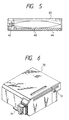
- Fig. 5 is a longitudinal cross-sectional view of an ink cartridge.
- Fig. 6 is a perspective view of a printing unit.
- standard hue means a color classified in the same hue when the color after dyed with an ink is compared with the standard color chart (Munsell color chart) in accordance with JIS Z 8721.
- the standard color chart in accordance with JIS Z 8721 is used for judging a color of the intended object by color samples and classifies hues into 10 colors of R, YR, Y, GY, G, BG, B, PB, P and PR.
- the present invention a feature that a dye of a high thermal diffusivity is used in the pale-colored ink, while a dye of a lower thermal diffusivity than the dye used in the pale-colored ink is used in the deep-colored ink.
- the ink having a low dye concentration (pale-colored ink) used in the present invention is an ink containing, preferably, a dye selected from among dyes having a color fastness of from Class 2 to Class 3 based on either the gray scale for assessing change in color or the gray scale for assessing staining of polyester, more preferably, a dye selected from among dyes having a color fastness of from Class 2 to Class 3 based on the gray scale for assessing change in color, while the ink having a high dye concentration (deep-colored ink) is an ink containing, preferably, a dye selected from among dyes having a color fastness higher than Class 3 based on both gray scale for assessing change in color and gray scale for assessing staining of polyester, more preferably, a dye selected from among dyes having a color fastness not lower than Class 4.
- color fastness means a color fastness as determined in accordance with "Method B in Testing Method for Color Fastness to Dry Heating” prescribed in JIS L 0879-1975 (180 ⁇ 2°C, 30 seconds).
- a deep-colored portion is mainly formed by the deep-color ink because sharp edge is required thereof. Since a shot-in ink quantity is also great, the deep-colored portion does not very conspicuously give a feeling of grain. On the other hand, since a pale-colored portion is mainly formed by the pale-color ink, and a shot-in ink quantity is also small, the pale-colored portion conspicuously gives a feeling of grain, and skitteriness of image becomes conspicuous.
- a dye having a low color fastness i.e., a dye having high heat diffusivity
- a dye having a high color fastness i.e., a dye having low heat diffusivity
- a dye having a high color fastness i.e., a dye having low heat diffusivity
- contrariwise has a high molecular weight and tends to form dots having sharp edge upon coloring.
- the above dye is used by incorporating it into the ink having a low dye concentration, so that the graininess of the image can be prevented by making good use of spreading of dot, and moreover the skitteriness of image can be prevented though the color depth may be somewhat lowered by the HT steaming process.
- dyes used in the present invention No particular limitation is imposed on dyes used in the present invention.
- preferable examples, from the viewpoints of coloring property and ejection property, of the dye used in the ink having a high dye concentration and having a color fastness higher than Class 3 based on both gray scale for assessing change in color and gray scale for assessing staining of polyester include C.I. Disperse Yellow 5, 42, 79, 82, 99, 100, 119, 122, 126, 160, 163, 184:1, 186, 192, 199, 204, 224 and 237; C.I. Disperse orange 13, 29, 30, 31:1, 33, 49, 54, 55, 56, 66, 73, 118, 119 and 163; C.I.
- preferable examples of the dye used in the ink having a low dye concentration and having a color fastness of from Class 2 to Class 3 based on either the gray scale for assessing change in color or the gray scale for assessing staining of polyester include C.I. Disperse yellow 7, 54, 64, 70, 71, 100 and 242; C.I. Disperse Orange 25, 37 and 119; C.I. Disperse Red 50, 60, 65, 146 and 239; C.I. Disperse Violet 27; C.I. Disperse Blue 26, 35, 55, 56, 81:1, 91 and 366.
- the content of the dye having a color fastness higher than Class 3 in the ink is within a range of preferably from 1 to 25 % by weight, more preferably from 1.5 to 20 % by weight based on the total weight of the ink. If the content of the disperse dye is lower than 1 % by weight, the color density on the resulting printed cloth may become insufficient in some cases. If the content of the dye exceeds 25 % by weight on the other hand, the resulting ink may be deteriorated in storage stability or cause ejection failure due to thickening or deposition attendant on evaporation of the ink in the vicinity of an orifice in some cases.
- the content of the dye having a color fastness of from Class 2 to Class 3 in the ink is within a range of from one third down to one tenth, preferably from one fourth down to one eighth by weight of the content of the dye having a color fastness higher than Class 3. If the content of the dye having a color fastness of from Class 2 to Class 3 exceeds one third of the content of the dye having a color fastness higher than Class 3, the effect of reducing graininess of cloth printed may become insufficient in some cases, resulting in a failure to provide a bright pictorial pattern.
- the effect of reducing graininess of cloth printed may also become insufficient at a medium-colored portion in some cases though no problem of graininess arises at a deep-colored portion and an extremely-pale-colored portion.
- the inks used in the present invention comprise one of the above-described dyes, a compound for dispersing such a dye and an aqueous medium.
- a compound for dispersing the dye may be used the so-called dispersing agent, surfactant, resinous dispersing agent or the like.
- the dispersing agent or surfactant may be used, for example, both anionic and nonionic types.
- anionic type examples include fatty acid salts, alkylsulfates, alkylbenzene sulfonates, alkylnaphthalene sulfonates, dialkylsulfosuccinates, salts of alkyl phosphates, naphthalenesulfonic acid-formalin condensates, polyoxyethylene alkylsulfates and substituted derivatives thereof.
- nonionic type examples include polyoxyethylene alkyl ethers, polyoxyethylene alkyl phenyl ethers, polyoxyethylene fatty acid esters, sorbitan fatty acid esters, polyoxyethylene sorbitan fatty acid esters, polyoxyethylene alkylamines, glycerol fatty acid esters, oxyethylene-oxypropylene block copolymers and substituted derivatives thereof.
- the resinous dispersing agent examples include block copolymers, random copolymers and graft copolymers composed of at least two monomers (preferably, at least one of which is a hydrophilic monomer) selected from styrene and derivatives thereof, vinylnaphthalene and derivatives thereof, aliphatic alcohol esters of ⁇ , ⁇ -ethylenically unsaturated carboxylic acids, acrylic acid and derivatives thereof, maleic acid and derivatives thereof, itaconic acid and derivatives thereof, fumaric acid and derivatives thereof, vinyl acetate, vinyl alcohol, vinylpyrrolidone, acrylamide, and derivatives thereof, and salts of these copolymers.
- These resinous dispersing agents may preferably be alkali-soluble resins which are soluble in an aqueous solution of a base.
- the inks used in the present invention comprise an aqueous medium.
- Water which is a component of the inks may be contained within a range of preferably from 10 to 93 % by weight, more preferably from 25 to 87 % by weight, most preferably from 30 to 82 % by weight based on the total weight of each ink.
- the aqueous medium preferably comprises at least one organic solvent in combination with water.
- the organic solvent include ketones and keto-alcohols such as acetone and diacetone alcohol; ethers such as tetrahydrofuran and dioxane; addition polymers of oxyethylene or oxypropylene, such as diethylene glycol, triethylene glycol, tetraethylene glycol, dipropylene glycol, tripropylene glycol, polyethylene glycol and polypropylene glycol; alkylene glycols the alkylene moiety of which has 2 to 6 carbon atoms, such as ethylene glycol, propylene glycol, trimethylene glycol, butylene glycol and hexylene glycol; thiodiglycol; glycerol and 1,2,6-hexanetriol; lower alkyl ethers of polyhydric alcohols, such as ethylene glycol monomethyl (or monoethyl) ether, diethylene glycol monomethyl (or monoethyl) ether and tri
- organic solvents may be used either singly or in any combination thereof if used in combination with water.
- the most preferable composition of the aqueous medium is such that at least one polyhydric alcohol is contained.
- a single solvent of thiodiglycol or diethylene glycol, or a mixed solvent system of diethylene glycol and thiodiglycol is particularly preferred.
- the content of the organic solvents is generally within a range of from 5 to 60 % by weight, preferably from 5 to 50 % by weight based on the total weight of the ink.
- viscosity modifiers such as polyvinyl alcohol, cellulosics and water-soluble resins
- surface tension modifiers such as diethanolamine and triethanolamine
- various kinds of dispersing agents, srnrfactants and/or the like may be optionally added as an ingredient for the inks for purposes other than the dispersion of the dye.
- Each of the inks used in the present invention can be prepared from the dye, the compound for dispersing the dye, the aqueous medium and optionally other additives using the conventionally-known dispersing method or mixing method, or the like.
- a material making up a cloth used in the present invention comprises fibers dyeable with disperse dyes.
- fibers dyeable with disperse dyes include fibers dyeable with disperse dyes.
- those comprising polyester, acetate and/or triacetate are preferred.
- those comprising polyester are particularly preferred.
- the cloth may be used in any form of woven fabric, knit fabric, nonwoven fabric and the like.
- Such a cloth preferably comprises 100 % of fibers dyeable with disperse dyes.
- blended yarn fabrics or nonwoven fabrics of the fibers dyeable with disperse dyes and other materials for example, rayon, cotton, polyurethane, acrylic, nylon, wool and silk may be used as cloths useful in the practice of the present invention so far as the blending ratio of the fibers dyeable with the disperse dyes is at least 30 %, preferably at least 50 %.
- the cloth used in the present invention as described above may be subjected to any conventionally-known pretreatment as needed.
- water-soluble polymer examples include known natural water-soluble polymers, for example, starches from corn, wheat and the like; cellulosics such as carboxymethyl cellulose, methyl cellulose and hydroxyethyl cellulose; polysaccharides such as sodium alginate, gum arabic, locust bean gum, tragacanth gum, guar gum and tamarind seed; proteins such as gelatin and casein; tannin and derivatives thereof; and lignin and derivatives thereof.
- known natural water-soluble polymers for example, starches from corn, wheat and the like
- cellulosics such as carboxymethyl cellulose, methyl cellulose and hydroxyethyl cellulose
- polysaccharides such as sodium alginate, gum arabic, locust bean gum, tragacanth gum, guar gum and tamarind seed
- proteins such as gelatin and casein; tannin and derivatives thereof; and lignin and derivatives thereof.
- Examples of synthetic water-soluble polymers include known polymers such as polyvinyl alcohol type compounds, polyethylene oxide type compounds, water-soluble acrylic polymers and water-soluble maleic anhydride polymers. Of these, the polysaccharide polymers and cellulosic polymers are preferred.
- water-soluble metal salt examples include compounds such as halides of alkali metals and alkaline earth metals, which form typical ionic crystals and an aqueous solution of which has a pH of 4 to 10.
- Representative examples of such compounds include NaCl, Na 2 SO 4 , KCl and CH 3 COONa for alkali metals, and CaCl 2 and MgCl 2 for alkaline earth metals. Of these, salts of Na, K and Ca are preferred.
- an ink-jet system used for the ink-jet printing process according to the present invention may be used any conventionally-known ink-jet system.
- the method described in, for example, Japanese Patent Application Laid-Open No. 54-59936, in which thermal energy is applied to an ink so as to undergo rapid volume change, and the ink is ejected from a nozzle by action force caused by this change of state, i.e., a bubble jet system is most effective.
- the reason for this is believed to be that if a printing head equipped with a plurality of nozzles is used, the above system is narrow in scattering of ejection velocities of the ink among individual nozzles, and the ejection velocities are summarized within a range of from 5 to 20 m/sec, and so the degree of penetration of ink droplets into a cloth at the time the ink containing a disperse dye impacts the cloth at this velocity becomes optimum.
- the ink-jet system as a printing method in the present invention, neither deposition of foreign matters on a heating head of the printing apparatus nor disconnection is caused even if printing is conducted continuously for a long period of time. Therefore, the printing can be conducted stably.
- an ejected ink droplet be within a range of from 20 to 200 pl
- a shot-in ink quantity be within a range of from 4 to 40 nl/mm 2
- a drive frequency be at least 1.5 kHz
- a head temperature be within a range of from 35 to 60°C
- an ejection velocity be within a range of from 5 to 20 m/sec.
- the inks applied to the cloth in the above-described manner only adheres to the cloth in this state. Accordingly, the cloth must be subsequently subjected to a dyeing treatment in which the dye in each ink is fixed to the fibers, and a treatment for removing undyed dyes. Such dyeing and removal of the undyed dyes may be conducted in accordance with the conventionally known methods.
- a high-temperature steaming process may preferably be used as the dyeing method.
- the treatment may preferably be conducted under conditions of 140 to 180°C and 2 to 30 minutes, more preferably under conditions of 160 to 180°C and 6 to 8 minutes.
- Inks of other hues are further used in combination with the above inks, whereby a full-color image can be obtained.
- the thus-obtained print can be cut into desired sizes as needed, and the cut pieces can then be subjected to processes required to obtain final processed articles, such as sewing, bonding and/or welding, thereby obtaining the processed articles such as neckties or handkerchiefs.
- an apparatus which is suitable for use in performing the ink-jet printing process according to the present invention, may be mentioned an apparatus in which thermal energy corresponding to printing signals is applied to an ink within a recording head, and ink droplets are generated by the thermal energy.
- an apparatus in which thermal energy corresponding to printing signals is applied to an ink within a recording head, and ink droplets are generated by the thermal energy.
- FIGS. 1, 2 and 3 Examples of the construction of an head, which is a main component of such an apparatus, are illustrated in Figs. 1, 2 and 3.
- a head 13 is formed by bonding a glass, ceramic, plastic plate or the like having a groove 14 through which ink is passed, to a heating head 15 used in thermal recording (the drawings show a thin-film head to which, however, the invention is not limited).
- the heating head 15 is composed of a protective film 16 formed of silicon oxide or the like, aluminum electrodes 17-1 and 17-2, a heating resistor layer 18 formed of nichrome or the like, a heat accumulating layer 19, and a substrate 20 made of alumina or the like having a good heat radiating property.
- An ink 21 comes up to an ejection orifice (a minute opening) 22 and forms a meniscus 23 owing to a pressure (not illustrated).
- the heating head 15 rapidly generates heat at the region shown by n to form bubbles in the ink 21 which is in contact with this region.
- the meniscus 23 of the ink is projected by the action of the pressure thus produced, and the ink 21 is ejected from the ejection orifice 22 to a printing medium 25 in the form of ink droplets 24.
- Fig. 3 illustrates an appearance of a multi-head composed of an array of a number of heads as shown in Fig. 1.
- the multi-head is formed by closely bonding a glass plate 27 having a number of grooves 26 to a heating head 28 similar to the heating head illustrated in Fig. 1.
- Fig. 1 is a cross-sectional view of a head taken along a flow path of the ink
- Fig. 2 is a cross-sectional view taken along line 2-2 in Fig. 1.
- Fig. 4 illustrates an example of an ink-jet printing apparatus in which the above head has been incorporated.
- reference numeral 61 designates a blade serving as a wiping member, one end of which is a stationary end held by a blade-holding member to form a cantilever.
- the blade 61 is provided at the position adjacent to the region in which a printing head 65 operates, and in this embodiment, is held in such a form that it protrudes into the course through which the printing head 65 is moved.
- Reference numeral 62 indicates a cap, which is provided at the home position adjacent to the blade 61, and is so constituted that it moves in the direction perpendicular to the direction in which the printing head 65 is moved and comes into contact with the face of ejection openings to cap it.
- Reference numeral 63 denotes an absorbing member provided adjoiningly to the blade 61 and, similar to the blade 61, held in such a form that it protrudes into the course through which the printing head 65 is moved.
- the above-described blade 61, cap 62 and absorbing member 63 constitute an ejection-recovery portion 64, where the blade 61 and absorbing member 63 remove off water, dust and/or the like from the face of the ink-ejecting openings.
- Reference numeral 65 designates the printing head having an ejection-energy-generating means and serving to eject the ink onto the printing medium set in an opposing relation to the ejection opening face provided with ejection openings to conduct printing.
- Reference numeral 66 indicates a carriage on which the printing head 65 is mounted so that the printing head 65 can be moved.
- the carriage 66 is slidably interlocked with a guide rod 67 and is connected (not illustrated) at its part to a belt 69 driven by a motor 68.
- the carriage 66 can be moved along the guide rod 67 and hence, the printing head 65 can be moved from a printing region to a region adjacent thereto.
- Reference numerals 51 and 52 denote a cloth feeding part from which cloths are separately inserted, and cloth feed rollers driven by a motor (not illustrated), respectively.
- the printing medium is fed to the position opposite to the ejection opening face of the printing head 65, and discharged from a cloth discharge section provided with cloth discharge rollers 53 with the progress of printing.
- the cap 62 in the head recovery portion 64 is receded from the path of motion of the printing head 65 when the printing head 65 is returned to its home position, for example, after completion of printing, and the blade 61 remains protruded into the path of motion. As a result, the ejection opening face of the printing head 65 is wiped. When the cap 62 comes into contact with the ejection opening face of the printing head 65 to cap it, the cap 62 is moved so as to protrude into the path of motion of the printing head 65.
- the cap 62 and the blade 61 are at the same positions as the positions for the wiping as described above. As a result, the ejection opening face of the printing head 65 is also wiped at the time of this movement.
- the above movement of the printing head 65 to its home position is made not only when the printing is completed or the printing head 65 is recovered for ejection, but also when the printing head 65 is moved between printing regions for the purpose of printing, during which it is moved to the home position adjacent to each printing region at given intervals, where the ejection opening face is wiped in accordance with this movement.
- Fig. 5 illustrates an exemplary ink cartridge 45 in which an ink to be fed to the head through an ink-feeding member, for example, a tube is contained.
- reference numeral 40 designates an ink container portion containing the ink to be fed, as exemplified by a bag for the ink.
- One end thereof is provided with a stopper 42 made of rubber.
- a needle (not illustrated) may be inserted into this stopper 42 so that the ink in the bag 40 for the ink can be fed to the head.
- Reference numeral 44 indicates an ink-absorbing member for receiving a waste ink.
- the ink container portion be formed of a polyolefin, in particular, polyethylene, at its surface with which the ink comes into contact.
- the ink-jet printing apparatus used in the present invention are not limited to the apparatus as described above in which the head and the ink cartridge are separately provided. Therefore, a device in which these members are integrally formed as shown in Fig. 6 can also be preferably used.
- reference numeral 70 designates a printing unit, in the interior of which an ink container portion containing an ink, for example, an ink-absorbing member, is contained.
- the printing unit 70 is so constructed that the ink in such an ink-absorbing member is ejected in the form of ink droplets through a head 71 having a plurality of orifices.
- polyurethane is preferably used as a material for the ink-absorbing member.
- Reference numeral 72 indicates an air passage for communicating the interior of the printing unit 70 with the atmosphere.
- This printing unit 70 can be used in place of the printing head 65 shown in Fig. 4, and is detachably installed on the carriage 66.
- the present invention may be applied to office uses, but is particularly suitable for industrial uses other than the office uses.
- a plain weave fabric formed of polyester yarn having an average thickness of 40 deniers composed of polyester filament fibers having an average thickness of 2 deniers was immersed in a 10 % aqueous solution of urea in advance, squeezed to a pickup of 60 % and then dried, thereby controlling the moisture regain of the plain weave fabric to 7 % to provide it as Cloth (A).
- the dispersions were further filtered through a Fluoropore Filter FP-250 (trade name, product of Sumitomo Electric Industries, Ltd.) to remove coarse particles, thereby obtaining Dye Dispersions (a) and (b).
- Dye Dispersion (b) described above 7 parts Thiodiglycol 15 parts Diethylene glycol 10 parts Tetraethylene glycol dimethyl ether 5 parts Ion-exchanged water 63 parts.
- the dispersions were further filtered through a Fluoropore Filter FP-250 (trade name, product of Sumitomo Electric Industries, Ltd.) to remove coarse particles, thereby obtaining Dye Dispersions (c) and (d).
- a plain weave fabric formed of polyester yarn having an average thickness of 70 deniers composed of polyester filament fibers having an average thickness of 0.7 deniers was immersed in a 0.1 % aqueous solution of carboxymethyl cellulose in advance, squeezed to a pickup of 60 % and then dried, thereby controlling the moisture regain of the plain weave fabric to 10 % to provide it as Cloth (B).
- the dispersions were further filtered through a Fluoropore Filter FP-250 (trade name, product of Sumitomo Electric Industries, Ltd.) to remove coarse particles, thereby obtaining Dye Dispersions (e) to (h).
- Dye Dispersion (f) described above 13 parts Thiodiglycol 20 parts Diethylene glycol 10 parts Ion-exchanged water 57 parts.
- Dye Dispersion (g) described above 40 parts Thiodiglycol 25 parts Diethylene glycol 8 parts Ion-exchanged water 27 parts.
- the dispersions were further filtered through a Fluoropore Filter FP-250 (trade name, product of Sumitomo Electric Industries, Ltd.) to remove coarse particles, thereby obtaining Dye Dispersions (i) and (j).
- the deep-color Ink (i) obtained in the above-described manner and the pale-color Ink (b) used in Example 1 were used to print the same pattern as in Example 1 on the same Cloth (A) as that used in Example 1 in the same manner as in Example 1.
- the thus-obtained print sample was then fixed by a steaming treatment at 180°C for 8 minutes. Thereafter, the sample was washed with water, subjected to reduction cleaning and dried in accordance with a method known per se in the art, thereby obtaining a cloth according to the comparative example, on which a pictorial pattern had been printed.
- the printed cloth thus obtained was evaluated as to (1) color depth, (2) graininess, (3) definition and (4) tint. The results are shown in Table 1.
- Dye Dispersion (j) described above 7 parts Thiodiglycol 15 parts Diethylene glycol 10 parts Isopropyl alcohol 5 parts Ion-exchanged water 63 parts.
- the pale-color Ink (j) obtained in the above-described manner and the deep-color Ink (a) used in Example 1 were used to print the same pattern as in Example 1 on the same Cloth (A) as that used in Example 1 in the same manner as in Example 1.
- the thus-obtained print sample was then fixed by a steaming treatment at 180°C for 8 minutes. Thereafter, the sample was washed with water, subjected to reduction cleaning and dried in accordance with a method known per se in the art, thereby obtaining a cloth according to the comparative example, on which a pictorial pattern had been printed.
- the printed cloth thus obtained was evaluated as to (1) color depth, (2) graininess, (3) definition and (4) tint. The results are shown in Table 1.
- a print patch of variable-density gradation which was divided into 21 grades between densities of 0 % and 100 %, was printed in the same manner as in the item (1). After the resultant print patch was subjected to a heat treatment and cleaning, it was visually observed as to whether graininess appeared or not, thereby ranking it in accordance with the following standard.
- a print patch of variable-density gradation which was divided into 21 grades between densities of 0 % and 100 %, was printed in the same manner as in the item (1).
- the resultant print patch was subjected to a heat treatment and cleaning, the chromaticities, L*a*b* of patch portions corresponding to 20, 40, 60, 80 and 100 % were measured by a spectrophotometer C-M2022 manufactured by MINOLTA CAMERA CO. LTD. to determine whether they were classified in the same hue in the Munsell color chart (JIS Z 8721) or not, thereby ranking the tint of the print sample in accordance with the following standard.
- a print patch of variable-density gradation which was divided into 21 grades between densities of 0 % and 100 %, was printed in the same manner as in the item (1) except that orange and yellow colors were mixed. After the resultant print patch was subjected to a heat treatment and cleaning, it was observed mainly at its pale-color-mixed portion as to whether skitteriness of image (graininess at a color-mixed portion) appeared or not, thereby ranking it in accordance with the following standard.
- an ink-jet printing process comprising the three steps of (a) applying inks containing a disperse dye, a compound for dispersing the disperse dye and an aqueous medium to a cloth comprising fibers dyeable with disperse dyes according to an ink-jet system (b) subjecting the cloth, to which the inks have been applied, to a heat treatment and (c) cleaning the heat-treated cloth, wherein the inks comprise two or more inks which separately contain disperse dyes of the same hue and are different in dye concentration, and the thermal diffusivity of the disperse dye used in the ink having a low dye concentration is higher than that of the disperse dye used in the ink having a high dye concentration.
Landscapes
- Engineering & Computer Science (AREA)
- Textile Engineering (AREA)
- Coloring (AREA)
- Ink Jet (AREA)
- Ink Jet Recording Methods And Recording Media Thereof (AREA)
- Inks, Pencil-Leads, Or Crayons (AREA)
Abstract
Description
- The present invention relates to an ink-jet printing process wherein printing is conducted on a cloth by ink-jet system to provide a print having excellent gradation and high saturation, and to a printed article obtained by such a process.
- At present, textile printing is principally conducted by screen printing or roller printing. Both methods are however unfit for multi-kind small-quantity production and difficult to quickly cope with the fashion of the day. Therefore, there has recently been a demand for establishment of an electronic printing system making no use of any plate.
- In compliance with this demand, a great number of textile printing processes according to an ink-jet system have been proposed. Various fields expect much from such textile printing processes.
- Requirements of the textile printing processes according to an ink-jet system include:
- (1) being able to achieve sufficient color depth upon coloring of ink;
- (2) being able to provide a print high in color yield of coloring matter on cloth and to conduct a waste water treatment after a cleaning step with ease;
- (3) causing little irregular bleeding due to color mixing between inks of different colors on cloth;
- (4) being able to provide prints with wide color reproductivity; and
- (5) being able to always conduct stable production of prints;
- (6) being able to provide images which does not conspicuously give a feeling of grain; and
- (7) being able to provide images inconspicuous in color unevenness (skitteriness of image) when mixing different colors.
- In order to satisfy these requirements, there have been made, for the requirements (1) to (5), such various proposals that various solvents are added to inks, shot-in ink quantity on cloth is controlled, and cloth is subjected to a pretreatment. As an ink-jet printing method for a polyester fabric, it is also disclosed in Japanese Patent Application Laid-Open No. 61-118477 to use disperse dyes having a sublimation temperature of 180°C or higher.
- Further, with respect to the requirement (6), it is disclosed in Japanese Patent Application Laid-Open No. 6-305131 to use two kinds of inks different in dye concentration to prevent graininess. The use of the inks simply different in dye concentration can reduce the graininess from a deep-colored portion to a medium- or pale-colored portion. However, individual dots become conspicuous at portions low in shot-in dot density per unit area like an area ranging from a pale-colored portion to an extremely-pale-colored portion. Further, skitteriness of image occurs when mixed with inks different in color. Therefore, such a method cannot achieve sufficient effect to reduce graininess or skitteriness of image.
- It is therefore an object of the present invention to provide an ink-jet printing process which can satisfy such requirements for the usual ink-jet printing as described above, particularly, the feeling of grain to image of the requirement (6) and the skitteriness of image of the requirement (7), when conducting ink-jet printing on a cloth composed mainly of fibers dyeable with disperse dyes, thereby providing a bright pictorial pattern having excellent gradation, and to a printed article obtained by such a process.
- The above object can be achieved by the present invention described below.
- According to the present invention, there is thus provided an ink-jet printing process comprising the three steps of:
- (a) applying inks containing a disperse dye, a compound for dispersing the disperse dye and an aqueous medium to a cloth comprising fibers dyeable with disperse dyes according to an ink-jet system;
- (b) subjecting the cloth, to which the inks have been applied, to a heat treatment; and
- (c) washing the heat-treated cloth, wherein the inks comprise two or more inks which separately contain disperse dyes of the same hue and different in dye concentration, and the thermal diffusivity of the disperse dye used in the ink having a low dye concentration is higher than that of the disperse dye used in the ink having a high dye concentration.
- According to the present invention, there is also provided a printed article obtained in accordance with the ink-jet printing process described above.
- Fig. 1 is a longitudinal cross-sectional view of a head of an ink-jet printing apparatus.
- Fig. 2 is a transverse cross-sectional view of the head of the ink-jet printing apparatus.
- Fig. 3 is a perspective view of the appearance of a multi-head which is an array of such heads as shown in Fig. 1.
- Fig. 4 is a perspective view of an illustrative ink-jet printing apparatus.
- Fig. 5 is a longitudinal cross-sectional view of an ink cartridge.
- Fig. 6 is a perspective view of a printing unit.
- The present invention will hereinafter be described in detail by preferred embodiments of the invention.
- The term "same hue" as used in the present invention means a color classified in the same hue when the color after dyed with an ink is compared with the standard color chart (Munsell color chart) in accordance with JIS Z 8721. The standard color chart in accordance with JIS Z 8721 is used for judging a color of the intended object by color samples and classifies hues into 10 colors of R, YR, Y, GY, G, BG, B, PB, P and PR.
- The present invention a feature that a dye of a high thermal diffusivity is used in the pale-colored ink, while a dye of a lower thermal diffusivity than the dye used in the pale-colored ink is used in the deep-colored ink.
- The ink having a low dye concentration (pale-colored ink) used in the present invention is an ink containing, preferably, a dye selected from among dyes having a color fastness of from
Class 2 to Class 3 based on either the gray scale for assessing change in color or the gray scale for assessing staining of polyester, more preferably, a dye selected from among dyes having a color fastness of fromClass 2 to Class 3 based on the gray scale for assessing change in color, while the ink having a high dye concentration (deep-colored ink) is an ink containing, preferably, a dye selected from among dyes having a color fastness higher than Class 3 based on both gray scale for assessing change in color and gray scale for assessing staining of polyester, more preferably, a dye selected from among dyes having a color fastness not lower than Class 4. - The term "color fastness" as used in the present invention means a color fastness as determined in accordance with "Method B in Testing Method for Color Fastness to Dry Heating" prescribed in JIS L 0879-1975 (180 ± 2°C, 30 seconds).
- The reason why such dyes are selected is as follows:
- In general, when gradation printing of the same hue is conducted with deep- and pale-color inks of the same hue, a deep-colored portion is mainly formed by the deep-color ink because sharp edge is required thereof. Since a shot-in ink quantity is also great, the deep-colored portion does not very conspicuously give a feeling of grain. On the other hand, since a pale-colored portion is mainly formed by the pale-color ink, and a shot-in ink quantity is also small, the pale-colored portion conspicuously gives a feeling of grain, and skitteriness of image becomes conspicuous.
- On one hand, a dye having a low color fastness, i.e., a dye having high heat diffusivity, generally has a low molecular weight and is weak in interaction between molecules when heated. Therefore, diffusivity of the dye becomes high on cloth, and dots spread upon coloring, so that the resulting image tends to reduce graininess. On the other hand, a dye having a high color fastness, i.e., a dye having low heat diffusivity, contrariwise has a high molecular weight and tends to form dots having sharp edge upon coloring. Therefore, it is considered that when a dye having a low sublimation fastness is used in the ink having a low dye concentration, and a dye having a high sublimation fastness is used in the ink having a high dye concentration, the graininess of the resulting print can be reduced, and the skitteriness of image of the print can be made inconspicuous, thereby providing a bright pictorial pattern having excellent gradation, wherein the edge of the image is sharp at a deep-colored portion, and graininess and skitteriness of image are reduced at a pale-colored portion.
- When a dye having a color fastness lower than
Class 2 is used in the ink having a low dye concentration, and a cloth printed is subjected to a dyeing treatment by a high-temperature (HT) steaming process or a thermosol process, the color depth and color tone of the resulting print may be deteriorated in some cases. Any dye having a color fastness of fromClass 2 to Class 3 has heretofore been said to be unsuitable for the HT steaming process and thermosol process. In the present invention, however, the above dye is used by incorporating it into the ink having a low dye concentration, so that the graininess of the image can be prevented by making good use of spreading of dot, and moreover the skitteriness of image can be prevented though the color depth may be somewhat lowered by the HT steaming process. - No particular limitation is imposed on dyes used in the present invention. However, preferable examples, from the viewpoints of coloring property and ejection property, of the dye used in the ink having a high dye concentration and having a color fastness higher than Class 3 based on both gray scale for assessing change in color and gray scale for assessing staining of polyester include C.I. Disperse Yellow 5, 42, 79, 82, 99, 100, 119, 122, 126, 160, 163, 184:1, 186, 192, 199, 204, 224 and 237; C.I.
Disperse orange 13, 29, 30, 31:1, 33, 49, 54, 55, 56, 66, 73, 118, 119 and 163; C.I. Disperse Red 54, 72, 73, 86, 88, 91, 92, 93, 111, 126, 127, 134, 135, 143, 145, 152, 153, 154, 159, 164, 167:1, 177, 181, 204, 206, 207, 221, 239, 240, 258, 277, 278, 283, 288, 311, 323, 343, 348, 356 and 362; C.I. Disperse Violet 26, 33, 46, 57 and 77; C.I. Disperse Blue 60, 73, 87, 113, 128, 143, 148, 154, 158, 165, 165:1, 165:2, 176, 183, 185, 197, 198, 201, 214, 224, 225, 257, 266, 267, 287, 354, 358, 365 and 368; and C.I. Disperse Green 6:1 and 9. - Besides, preferable examples of the dye used in the ink having a low dye concentration and having a color fastness of from
Class 2 to Class 3 based on either the gray scale for assessing change in color or the gray scale for assessing staining of polyester include C.I. Disperse yellow 7, 54, 64, 70, 71, 100 and 242; C.I. DisperseOrange 25, 37 and 119; C.I. DisperseRed 50, 60, 65, 146 and 239; C.I. DisperseViolet 27; C.I. DisperseBlue 26, 35, 55, 56, 81:1, 91 and 366. - The content of the dye having a color fastness higher than Class 3 in the ink is within a range of preferably from 1 to 25 % by weight, more preferably from 1.5 to 20 % by weight based on the total weight of the ink. If the content of the disperse dye is lower than 1 % by weight, the color density on the resulting printed cloth may become insufficient in some cases. If the content of the dye exceeds 25 % by weight on the other hand, the resulting ink may be deteriorated in storage stability or cause ejection failure due to thickening or deposition attendant on evaporation of the ink in the vicinity of an orifice in some cases.
- The content of the dye having a color fastness of from
Class 2 to Class 3 in the ink is within a range of from one third down to one tenth, preferably from one fourth down to one eighth by weight of the content of the dye having a color fastness higher than Class 3. If the content of the dye having a color fastness of fromClass 2 to Class 3 exceeds one third of the content of the dye having a color fastness higher than Class 3, the effect of reducing graininess of cloth printed may become insufficient in some cases, resulting in a failure to provide a bright pictorial pattern. If the content is lower than one tenth on the other hand, the effect of reducing graininess of cloth printed may also become insufficient at a medium-colored portion in some cases though no problem of graininess arises at a deep-colored portion and an extremely-pale-colored portion. - The inks used in the present invention comprise one of the above-described dyes, a compound for dispersing such a dye and an aqueous medium. As the compound for dispersing the dye, may be used the so-called dispersing agent, surfactant, resinous dispersing agent or the like. As the dispersing agent or surfactant, may be used, for example, both anionic and nonionic types. Examples of the anionic type include fatty acid salts, alkylsulfates, alkylbenzene sulfonates, alkylnaphthalene sulfonates, dialkylsulfosuccinates, salts of alkyl phosphates, naphthalenesulfonic acid-formalin condensates, polyoxyethylene alkylsulfates and substituted derivatives thereof. Examples of the nonionic type include polyoxyethylene alkyl ethers, polyoxyethylene alkyl phenyl ethers, polyoxyethylene fatty acid esters, sorbitan fatty acid esters, polyoxyethylene sorbitan fatty acid esters, polyoxyethylene alkylamines, glycerol fatty acid esters, oxyethylene-oxypropylene block copolymers and substituted derivatives thereof.
- Examples of the resinous dispersing agent include block copolymers, random copolymers and graft copolymers composed of at least two monomers (preferably, at least one of which is a hydrophilic monomer) selected from styrene and derivatives thereof, vinylnaphthalene and derivatives thereof, aliphatic alcohol esters of α,β-ethylenically unsaturated carboxylic acids, acrylic acid and derivatives thereof, maleic acid and derivatives thereof, itaconic acid and derivatives thereof, fumaric acid and derivatives thereof, vinyl acetate, vinyl alcohol, vinylpyrrolidone, acrylamide, and derivatives thereof, and salts of these copolymers. These resinous dispersing agents may preferably be alkali-soluble resins which are soluble in an aqueous solution of a base.
- The inks used in the present invention comprise an aqueous medium. Water which is a component of the inks may be contained within a range of preferably from 10 to 93 % by weight, more preferably from 25 to 87 % by weight, most preferably from 30 to 82 % by weight based on the total weight of each ink.
- The aqueous medium preferably comprises at least one organic solvent in combination with water. Examples of the organic solvent include ketones and keto-alcohols such as acetone and diacetone alcohol; ethers such as tetrahydrofuran and dioxane; addition polymers of oxyethylene or oxypropylene, such as diethylene glycol, triethylene glycol, tetraethylene glycol, dipropylene glycol, tripropylene glycol, polyethylene glycol and polypropylene glycol; alkylene glycols the alkylene moiety of which has 2 to 6 carbon atoms, such as ethylene glycol, propylene glycol, trimethylene glycol, butylene glycol and hexylene glycol; thiodiglycol; glycerol and 1,2,6-hexanetriol; lower alkyl ethers of polyhydric alcohols, such as ethylene glycol monomethyl (or monoethyl) ether, diethylene glycol monomethyl (or monoethyl) ether and triethylene glycol monomethyl (or monoethyl) ether; lower dialkyl ethers of polyhydric alcohols, such as triethylene glycol dimethyl (or diethyl) ether and tetraethylene glycol dimethyl (or diethyl) ether; sulfolane; N-methyl-2-pyrrolidone; 1,3-dimethyl-2-imidazolidinone; and the like.
- The above-described organic solvents may be used either singly or in any combination thereof if used in combination with water. However, the most preferable composition of the aqueous medium is such that at least one polyhydric alcohol is contained. Among others, a single solvent of thiodiglycol or diethylene glycol, or a mixed solvent system of diethylene glycol and thiodiglycol is particularly preferred. The content of the organic solvents is generally within a range of from 5 to 60 % by weight, preferably from 5 to 50 % by weight based on the total weight of the ink.
- The principal components of the inks used in the present invention are as described above. However, various kinds of known additives such as viscosity modifiers, surface tension modifiers, optical whitening agents and antifoaming agents may be added as needed. Specific examples thereof include viscosity modifiers such as polyvinyl alcohol, cellulosics and water-soluble resins; surface tension modifiers such as diethanolamine and triethanolamine; pH adjusters according to buffer solutions; and mildewproofing agents.
- In addition, various kinds of dispersing agents, srnrfactants and/or the like may be optionally added as an ingredient for the inks for purposes other than the dispersion of the dye.
- Each of the inks used in the present invention can be prepared from the dye, the compound for dispersing the dye, the aqueous medium and optionally other additives using the conventionally-known dispersing method or mixing method, or the like.
- A material making up a cloth used in the present invention comprises fibers dyeable with disperse dyes. Among others, those comprising polyester, acetate and/or triacetate are preferred. Of these, those comprising polyester are particularly preferred. The cloth may be used in any form of woven fabric, knit fabric, nonwoven fabric and the like.
- Such a cloth preferably comprises 100 % of fibers dyeable with disperse dyes. However, blended yarn fabrics or nonwoven fabrics of the fibers dyeable with disperse dyes and other materials, for example, rayon, cotton, polyurethane, acrylic, nylon, wool and silk may be used as cloths useful in the practice of the present invention so far as the blending ratio of the fibers dyeable with the disperse dyes is at least 30 %, preferably at least 50 %.
- The cloth used in the present invention as described above may be subjected to any conventionally-known pretreatment as needed. In particular, it is preferable to contain at least one of urea, a water-soluble polymer, a water-soluble metal salt and the like in an amount of 0.01 to 20 % by weight in the cloth.
- Examples of the water-soluble polymer include known natural water-soluble polymers, for example, starches from corn, wheat and the like; cellulosics such as carboxymethyl cellulose, methyl cellulose and hydroxyethyl cellulose; polysaccharides such as sodium alginate, gum arabic, locust bean gum, tragacanth gum, guar gum and tamarind seed; proteins such as gelatin and casein; tannin and derivatives thereof; and lignin and derivatives thereof.
- Examples of synthetic water-soluble polymers include known polymers such as polyvinyl alcohol type compounds, polyethylene oxide type compounds, water-soluble acrylic polymers and water-soluble maleic anhydride polymers. Of these, the polysaccharide polymers and cellulosic polymers are preferred.
- Examples of the water-soluble metal salt include compounds such as halides of alkali metals and alkaline earth metals, which form typical ionic crystals and an aqueous solution of which has a pH of 4 to 10. Representative examples of such compounds include NaCl, Na2SO4, KCl and CH3COONa for alkali metals, and CaCl2 and MgCl2 for alkaline earth metals. Of these, salts of Na, K and Ca are preferred.
- As an ink-jet system used for the ink-jet printing process according to the present invention, may be used any conventionally-known ink-jet system. However, the method described in, for example, Japanese Patent Application Laid-Open No. 54-59936, in which thermal energy is applied to an ink so as to undergo rapid volume change, and the ink is ejected from a nozzle by action force caused by this change of state, i.e., a bubble jet system, is most effective.
- The reason for this is believed to be that if a printing head equipped with a plurality of nozzles is used, the above system is narrow in scattering of ejection velocities of the ink among individual nozzles, and the ejection velocities are summarized within a range of from 5 to 20 m/sec, and so the degree of penetration of ink droplets into a cloth at the time the ink containing a disperse dye impacts the cloth at this velocity becomes optimum.
- By using the ink-jet system as a printing method in the present invention, neither deposition of foreign matters on a heating head of the printing apparatus nor disconnection is caused even if printing is conducted continuously for a long period of time. Therefore, the printing can be conducted stably.
- As conditions under which a particularly high effect can be achieved by such an ink-jet system, it is preferred that an ejected ink droplet be within a range of from 20 to 200 pl, a shot-in ink quantity be within a range of from 4 to 40 nl/mm2, a drive frequency be at least 1.5 kHz, a head temperature be within a range of from 35 to 60°C and an ejection velocity be within a range of from 5 to 20 m/sec.
- The inks applied to the cloth in the above-described manner only adheres to the cloth in this state. Accordingly, the cloth must be subsequently subjected to a dyeing treatment in which the dye in each ink is fixed to the fibers, and a treatment for removing undyed dyes. Such dyeing and removal of the undyed dyes may be conducted in accordance with the conventionally known methods.
- Among others, a high-temperature steaming process (HT steaming process) may preferably be used as the dyeing method. In the case of the HT steaming process, the treatment may preferably be conducted under conditions of 140 to 180°C and 2 to 30 minutes, more preferably under conditions of 160 to 180°C and 6 to 8 minutes.
- Inks of other hues are further used in combination with the above inks, whereby a full-color image can be obtained.
- Incidentally, the thus-obtained print can be cut into desired sizes as needed, and the cut pieces can then be subjected to processes required to obtain final processed articles, such as sewing, bonding and/or welding, thereby obtaining the processed articles such as neckties or handkerchiefs.
- As an illustrative example of an apparatus, which is suitable for use in performing the ink-jet printing process according to the present invention, may be mentioned an apparatus in which thermal energy corresponding to printing signals is applied to an ink within a recording head, and ink droplets are generated by the thermal energy. Such an apparatus will hereinafter be described.
- Examples of the construction of an head, which is a main component of such an apparatus, are illustrated in Figs. 1, 2 and 3.
- A
head 13 is formed by bonding a glass, ceramic, plastic plate or the like having agroove 14 through which ink is passed, to aheating head 15 used in thermal recording (the drawings show a thin-film head to which, however, the invention is not limited). Theheating head 15 is composed of aprotective film 16 formed of silicon oxide or the like, aluminum electrodes 17-1 and 17-2, aheating resistor layer 18 formed of nichrome or the like, aheat accumulating layer 19, and asubstrate 20 made of alumina or the like having a good heat radiating property. - An
ink 21 comes up to an ejection orifice (a minute opening) 22 and forms ameniscus 23 owing to a pressure (not illustrated). - Now, upon application of electric signals to the electrodes 17-1, 17-2, the
heating head 15 rapidly generates heat at the region shown by n to form bubbles in theink 21 which is in contact with this region. Themeniscus 23 of the ink is projected by the action of the pressure thus produced, and theink 21 is ejected from theejection orifice 22 to aprinting medium 25 in the form ofink droplets 24. - Fig. 3 illustrates an appearance of a multi-head composed of an array of a number of heads as shown in Fig. 1. The multi-head is formed by closely bonding a
glass plate 27 having a number ofgrooves 26 to aheating head 28 similar to the heating head illustrated in Fig. 1. - Incidentally, Fig. 1 is a cross-sectional view of a head taken along a flow path of the ink, and Fig. 2 is a cross-sectional view taken along line 2-2 in Fig. 1.
- Fig. 4 illustrates an example of an ink-jet printing apparatus in which the above head has been incorporated.
- In Fig. 4,
reference numeral 61 designates a blade serving as a wiping member, one end of which is a stationary end held by a blade-holding member to form a cantilever. Theblade 61 is provided at the position adjacent to the region in which aprinting head 65 operates, and in this embodiment, is held in such a form that it protrudes into the course through which theprinting head 65 is moved. -
Reference numeral 62 indicates a cap, which is provided at the home position adjacent to theblade 61, and is so constituted that it moves in the direction perpendicular to the direction in which theprinting head 65 is moved and comes into contact with the face of ejection openings to cap it.Reference numeral 63 denotes an absorbing member provided adjoiningly to theblade 61 and, similar to theblade 61, held in such a form that it protrudes into the course through which theprinting head 65 is moved. - The above-described
blade 61,cap 62 and absorbingmember 63 constitute an ejection-recovery portion 64, where theblade 61 and absorbingmember 63 remove off water, dust and/or the like from the face of the ink-ejecting openings. -
Reference numeral 65 designates the printing head having an ejection-energy-generating means and serving to eject the ink onto the printing medium set in an opposing relation to the ejection opening face provided with ejection openings to conduct printing.Reference numeral 66 indicates a carriage on which theprinting head 65 is mounted so that theprinting head 65 can be moved. - The
carriage 66 is slidably interlocked with aguide rod 67 and is connected (not illustrated) at its part to abelt 69 driven by amotor 68. Thus, thecarriage 66 can be moved along theguide rod 67 and hence, theprinting head 65 can be moved from a printing region to a region adjacent thereto. -
Reference numerals printing head 65, and discharged from a cloth discharge section provided withcloth discharge rollers 53 with the progress of printing. - In the above construction, the
cap 62 in thehead recovery portion 64 is receded from the path of motion of theprinting head 65 when theprinting head 65 is returned to its home position, for example, after completion of printing, and theblade 61 remains protruded into the path of motion. As a result, the ejection opening face of theprinting head 65 is wiped. When thecap 62 comes into contact with the ejection opening face of theprinting head 65 to cap it, thecap 62 is moved so as to protrude into the path of motion of theprinting head 65. - When the
printing head 65 is moved from its home position to the position at which printing is started, thecap 62 and theblade 61 are at the same positions as the positions for the wiping as described above. As a result, the ejection opening face of theprinting head 65 is also wiped at the time of this movement. - The above movement of the
printing head 65 to its home position is made not only when the printing is completed or theprinting head 65 is recovered for ejection, but also when theprinting head 65 is moved between printing regions for the purpose of printing, during which it is moved to the home position adjacent to each printing region at given intervals, where the ejection opening face is wiped in accordance with this movement. - Fig. 5 illustrates an
exemplary ink cartridge 45 in which an ink to be fed to the head through an ink-feeding member, for example, a tube is contained. - Here,
reference numeral 40 designates an ink container portion containing the ink to be fed, as exemplified by a bag for the ink. One end thereof is provided with astopper 42 made of rubber. A needle (not illustrated) may be inserted into thisstopper 42 so that the ink in thebag 40 for the ink can be fed to the head.Reference numeral 44 indicates an ink-absorbing member for receiving a waste ink. - In this invention, it is preferable that the ink container portion be formed of a polyolefin, in particular, polyethylene, at its surface with which the ink comes into contact.
- The ink-jet printing apparatus used in the present invention are not limited to the apparatus as described above in which the head and the ink cartridge are separately provided. Therefore, a device in which these members are integrally formed as shown in Fig. 6 can also be preferably used.
- In Fig. 6,
reference numeral 70 designates a printing unit, in the interior of which an ink container portion containing an ink, for example, an ink-absorbing member, is contained. Theprinting unit 70 is so constructed that the ink in such an ink-absorbing member is ejected in the form of ink droplets through ahead 71 having a plurality of orifices. - In the present invention, polyurethane is preferably used as a material for the ink-absorbing member.
Reference numeral 72 indicates an air passage for communicating the interior of theprinting unit 70 with the atmosphere. Thisprinting unit 70 can be used in place of theprinting head 65 shown in Fig. 4, and is detachably installed on thecarriage 66. - The present invention may be applied to office uses, but is particularly suitable for industrial uses other than the office uses.
- The present invention will hereinafter be described more specifically by the following Examples and Comparative Examples. Incidentally, all designations of "part" or "parts" and "%" as will be used in the following examples mean part or parts by weight and % by weight unless expressly noted.
- A plain weave fabric formed of polyester yarn having an average thickness of 40 deniers composed of polyester filament fibers having an average thickness of 2 deniers was immersed in a 10 % aqueous solution of urea in advance, squeezed to a pickup of 60 % and then dried, thereby controlling the moisture regain of the plain weave fabric to 7 % to provide it as Cloth (A).
-
β-Naphthalenesulfonic acid- formaldehyde condensate 20 parts Ion-exchanged water 55 parts Diethylene glycol 10 parts. - The above components were mixed into a solution. To each of this solution, were separately added 15 parts of the following disperse dyes to premix the mixtures for 30 minutes. Thereafter, the resulting premixes were subjected to a dispersion treatment under the following conditions:
- Disperse dye: C.I. Disperse Blue 165 (for Dye Dispersion (a))
C.I. Disperse Blue 56 (for Dye Dispersion (b)) - Dispersing machine: Sand Grinder (manufactured by Igarashi Kikai K.K.)
- Grinding medium: zirconium beads (diameter: 1 mm)
- Packing rate of the grinding medium: 50 % (by volume)
- Number of revolutions: 1,500 rpm
- Grinding time: 3 hours.
- The dispersions were further filtered through a Fluoropore Filter FP-250 (trade name, product of Sumitomo Electric Industries, Ltd.) to remove coarse particles, thereby obtaining Dye Dispersions (a) and (b).
-
Dye Dispersion (a) described above 40 parts Thiodiglycol 24 parts Diethylene glycol 11 parts Ion-exchanged water 25 parts. - All the above components were mixed, and the resulting liquid mixture was adjusted to pH 8 with sodium hydroxide, stirred for 2 hours and then filtered through a Fluoropore Filter FP-100 (trade name, product of Sumitomo Electric Industries, Ltd.), thereby preparing Ink (a).
-
Dye Dispersion (b) described above 7 parts Thiodiglycol 15 parts Diethylene glycol 10 parts Tetraethylene glycol dimethyl ether 5 parts Ion-exchanged water 63 parts. - All the above components were mixed, and the resulting liquid mixture was adjusted to pH 8 with sodium hydroxide, stirred for 2 hours and then filtered through a Fluoropore Filter FP-100 (trade name, product of Sumitomo Electric Industries, Ltd.), thereby preparing Ink (b).
- Two kinds of the deep-color and pale-color Inks (a) and (b) obtained in the above-described manner were charged in a Color Bubble Jet Printer BJC600 (trade name, manufactured by Canon Inc.) to print a gradation pattern and an image on the Cloth (A). The thus-obtained print sample was then fixed by a steaming treatment at 180°C for 8 minutes. Thereafter, the sample was washed with water, subjected to reduction cleaning and dried in accordance with a method known per se in the art, thereby obtaining a cloth according to this example, on which a pictorial pattern had been printed. The printed cloth thus obtained was evaluated as to (1) color depth, (2) graininess, (3) definition and (4) tint. The results are shown in Table 1. As apparent from Table 1, it is understood that in Inks (a) and (b) in which dyes of the same hue were separately used, the dye having a high color fastness was used in the ink having a high dye concentration, and the dye having a low color fastness was used in the ink having a low dye concentration, thereby permitting the provision of a bright pattern having high color depth and excellent definition without causing any graininess of the image.
-
Sodium lignin sulfonate 15 parts Ion-exchanged water 55 parts Diethylene glycol 15 parts. - The above components were mixed into a solution. To each of this solution, were separately added 15 parts of the following disperse dyes to premix the mixtures for 30 minutes. Thereafter, the resulting premixes were subjected to a dispersion treatment under the following conditions:
- Disperse dye: C.I. Disperse Red 288 (for Dye Dispersion (c))
C.I. Disperse Red 60 (for Dye Dispersion (d)) - Dispersing machine: Sand Grinder (manufactured by Igarashi Kikai K.K.)
- Grinding medium: zirconium beads (diameter: 0.5 mm)
- Packing rate of the grinding medium: 70 % (by volume)
- Number of revolutions: 1,500 rpm
- Grinding time: 3 hours.
- The dispersions were further filtered through a Fluoropore Filter FP-250 (trade name, product of Sumitomo Electric Industries, Ltd.) to remove coarse particles, thereby obtaining Dye Dispersions (c) and (d).
-
Dye Dispersion (c) described above 35 parts Thiodiglycol 19 parts Diethylene glycol 11 parts Isopropyl alcohol 5 parts Ion-exchanged water 30 parts. - All the above components were mixed, and the resulting liquid mixture was adjusted to pH 8 with sodium hydroxide, stirred for 2 hours and then filtered through a Fluoropore Filter FP-100 (trade name, product of Sumitomo Electric Industries, Ltd.), thereby preparing Ink (c).
-
Dye Dispersion (d) described above 10 parts Thiodiglycol 15 parts Diethylene glycol 10 parts Triethylene glycol 5 parts Ion-exchanged water 60 parts. - All the above components were mixed, and the resulting liquid mixture was adjusted to pH 8 with sodium hydroxide, stirred for 2 hours and then filtered through a Fluoropore Filter FP-100 (trade name, product of Sumitomo Electric Industries, Ltd.), thereby preparing Ink (d).
- Two kinds of the deep-color and pale-color Inks (c) and (d) obtained in the above-described manner were charged in a Color Bubble Jet Printer BJC600 (trade name, manufactured by Canon Inc.) to print a gradation pattern and an image on the Cloth (A). The thus-obtained print sample was then fixed by a steaming treatment at 180°C for 8 minutes. Thereafter, the sample was washed with water, subjected to reduction cleaning and dried in accordance with a method known per se in the art, thereby obtaining a cloth according to this example, on which a pictorial pattern had been printed. The printed cloth thus obtained was evaluated as to (1) color depth, (2) graininess, (3) definition and (4) tint. The results are shown in Table 1. As apparent from Table 1, it is understood that in Inks (c) and (d) in which dyes of the same hue were separately used, the dye having a high color fastness was used in the ink having a high dye concentration, and the dye having a low color fastness was used in the ink having a low dye concentration, thereby permitting the provision of a bright pattern having high color depth and excellent definition without causing any graininess of the image.
- A plain weave fabric formed of polyester yarn having an average thickness of 70 deniers composed of polyester filament fibers having an average thickness of 0.7 deniers was immersed in a 0.1 % aqueous solution of carboxymethyl cellulose in advance, squeezed to a pickup of 60 % and then dried, thereby controlling the moisture regain of the plain weave fabric to 10 % to provide it as Cloth (B). Preparation of Dye Dispersions (e) to (h):
Sodium polyoxyethylene alkyl ether sulfate 5 parts β-Naphthalenesulfonic acid-formaldehyde condensate 10 parts Ion-exchanged water 55 parts Ethylene glycol 20 parts. - The above components were mixed into a solution. To each of this solution, were separately added 10 parts of the following disperse dyes to premix the mixtures for 30 minutes. Thereafter, the resulting premixes were subjected to a dispersion treatment under the following conditions:
- Disperse dye: C.I. Disperse Orange 30 (for Dye Dispersion (e))
C.I. Disperse Orange 37 (for Dye Dispersion (f))
C.I. Disperse Yellow 42 (for Dye Dispersion (g))
C.I. Disperse Yellow 54 (for Dye Dispersion (h)) - Dispersing machine: Sand Grinder (manufactured by Igarashi Kikai K.K.)
- Grinding medium: zirconium beads (diameter: 1 mm)
- Packing rate of the grinding medium: 50 % (by volume)
- Number of revolutions: 1,500 rpm
- Grinding time: 3 hours.
- The dispersions were further filtered through a Fluoropore Filter FP-250 (trade name, product of Sumitomo Electric Industries, Ltd.) to remove coarse particles, thereby obtaining Dye Dispersions (e) to (h).
-
Dye Dispersion (e) described above 50 parts Thiodiglycol 24 parts Diethylene glycol 11 parts Ion-exchanged water 15 parts. - All the above components were mixed, and the resulting liquid mixture was adjusted to pH 8 with sodium hydroxide, stirred for 2 hours and then filtered through a Fluoropore Filter FP-100 (trade name, product of Sumitomo Electric Industries, Ltd.), thereby preparing Ink (e).
-
Dye Dispersion (f) described above 13 parts Thiodiglycol 20 parts Diethylene glycol 10 parts Ion-exchanged water 57 parts. - All the above components were mixed, and the resulting liquid mixture was adjusted to pH 8 with sodium hydroxide, stirred for 2 hours and then filtered through a Fluoropore Filter FP-100 (trade name, product of Sumitomo Electric Industries, Ltd.), thereby preparing Ink (f).
-
Dye Dispersion (g) described above 40 parts Thiodiglycol 25 parts Diethylene glycol 8 parts Ion-exchanged water 27 parts. - All the above components were mixed, and the resulting liquid mixture was adjusted to pH 8 with sodium hydroxide, stirred for 2 hours and then filtered through a Fluoropore Filter FP-100 (trade name, product of Sumitomo Electric Industries, Ltd.), thereby preparing Ink (g).
-
Dye Dispersion (h) described above 6 parts Thiodiglycol 28 parts Diethylene glycol 15 parts Ion-exchanged water 51 parts. - All the above components were mixed, and the resulting liquid mixture was adjusted to pH 8 with sodium hydroxide, stirred for 2 hours and then filtered through a Fluoropore Filter FP-100 (trade name, product of Sumitomo Electric Industries, Ltd.), thereby preparing Ink (h).
- Four kinds of the deep-color and pale-color Inks (e), (f), (g) and (h) obtained in the above-described manner were charged in a Color Bubble Jet Printer BJC600 (trade name, manufactured by Canon Inc.) to print a gradation pattern and an image on the Cloth (B). The thus-obtained print sample was then fixed by a steaming treatment at 180°C for 8 minutes. Thereafter, the sample was washed with water, subjected to reduction cleaning and dried in accordance with a method known per se in the art, thereby obtaining a cloth according to this example, on which a pictorial pattern had been printed. The printed cloth thus obtained was evaluated as to (1) color depth, (2) graininess, (3) definition, (4) tint and (5) skitteriness of image. The results are shown in Table 1.
- As apparent from Table 1, it is understood that in Inks (e) and (f), and (g) and (h) in which dyes of the same hue were separately used, the dyes having a high color fastness were used in the inks having a high dye concentration, and the dyes having a low color fastness were used in the inks having a low dye concentration, thereby permitting the provision of a bright pattern having high color depth and excellent definition without causing any graininess of the image. Inks (e) and (f) were of an orange color, while Inks (g) and (h) were of a yellow color. Even when these colors were mixed, a pictorial pattern free of any skitteriness of image was able to be obtained.
-
β-Naphthalenesulfonic acid- formaldehyde condensate 20 parts Ion-exchanged water 55 parts Diethylene glycol 10 parts. - The above components were mixed into a solution. To each of this solution, were separately added 15 parts of the following disperse dyes to premix the mixtures for 30 minutes. Thereafter, the resulting premixes were subjected to a dispersion treatment under the following conditions:
- Disperse dye: C.I. Disperse Blue 354 (for Dye Dispersion (i))
C.I. Disperse Blue 158 (for Dye Dispersion (j)) - Dispersing machine: Sand Grinder (manufactured by Igarashi Kikai K.K.)
- Grinding medium: zirconium beads (diameter: 1 mm)
- Packing rate of the grinding medium: 50 % (by volume)
- Number of revolutions: 1,500 rpm
- Grinding time: 3 hours.
- The dispersions were further filtered through a Fluoropore Filter FP-250 (trade name, product of Sumitomo Electric Industries, Ltd.) to remove coarse particles, thereby obtaining Dye Dispersions (i) and (j).
-
Dye Dispersion (i) described above 40 parts Thiodiglycol 24 parts Diethylene glycol 11 parts Ion-exchanged water 25 parts. - All the above components were mixed, and the resulting liquid mixture was adjusted to pH 8 with sodium hydroxide, stirred for 2 hours and then filtered through a Fluoropore Filter FP-100 (trade name, product of Sumitomo Electric Industries, Ltd.), thereby preparing Ink (i).
- The deep-color Ink (i) obtained in the above-described manner and the pale-color Ink (b) used in Example 1 (wherein the inks were inks prepared by separately using dyes different in hue) were used to print the same pattern as in Example 1 on the same Cloth (A) as that used in Example 1 in the same manner as in Example 1. The thus-obtained print sample was then fixed by a steaming treatment at 180°C for 8 minutes. Thereafter, the sample was washed with water, subjected to reduction cleaning and dried in accordance with a method known per se in the art, thereby obtaining a cloth according to the comparative example, on which a pictorial pattern had been printed. The printed cloth thus obtained was evaluated as to (1) color depth, (2) graininess, (3) definition and (4) tint. The results are shown in Table 1.
- As apparent from Table 1, it is understood that even when the dye having a high color fastness was used in the ink having a high dye concentration, and the dye having a low color fastness was used in the ink having a low dye concentration, the tint of the resulting image was changed due to the use of the dyes different in hue though no problems arose on the color depth, graininess and definition of the image.
-
Dye Dispersion (j) described above 7 parts Thiodiglycol 15 parts Diethylene glycol 10 parts Isopropyl alcohol 5 parts Ion-exchanged water 63 parts. - All the above components were mixed, and the resulting liquid mixture was adjusted to pH 8 with sodium hydroxide, stirred for 2 hours and then filtered through a Fluoropore Filter FP-100 (trade name, product of Sumitomo Electric Industries, Ltd.), thereby preparing Ink (j).
- The pale-color Ink (j) obtained in the above-described manner and the deep-color Ink (a) used in Example 1 were used to print the same pattern as in Example 1 on the same Cloth (A) as that used in Example 1 in the same manner as in Example 1. The thus-obtained print sample was then fixed by a steaming treatment at 180°C for 8 minutes. Thereafter, the sample was washed with water, subjected to reduction cleaning and dried in accordance with a method known per se in the art, thereby obtaining a cloth according to the comparative example, on which a pictorial pattern had been printed. The printed cloth thus obtained was evaluated as to (1) color depth, (2) graininess, (3) definition and (4) tint. The results are shown in Table 1.
- As apparent from Table 1, it is understood that since the dyes having a high color fastness were used in both ink having a high dye concentration and ink having a low dye concentration, the printed cloth clearly gave a feeling of grain at a pale-colored portion though no problems arose on the color depth, definition and tint.
-
Dye Dispersion (f) described above 35 parts Thiodiglycol 19 parts Diethylene glycol 11 parts Isopropyl alcohol 5 parts Ion-exchanged water 30 parts. - All the above components were mixed, and the resulting liquid mixture was adjusted to pH 8 with sodium hydroxide, stirred for 2 hours and then filtered through a Fluoropore Filter FP-100 (trade name, product of Sumitomo Electric Industries, Ltd.), thereby preparing Ink (k).
-
Dye Dispersion (c) described above 10 parts Thiodiglycol 15 parts Diethylene glycol 10 parts Triethylene glycol 5 parts Ion-exchanged water 60 parts. - All the above components were mixed, and the resulting liquid mixture was adjusted to pH 8 with sodium hydroxide, stirred for 2 hours and then filtered through a Fluoropore Filter FP-100 (trade name, product of Sumitomo Electric Industries, Ltd.), thereby preparing Ink (ℓ).
- Two kinds of the deep-color and pale-color Inks (k) and (ℓ) obtained in the above-described manner (wherein the inks were inks prepared by separately using dyes different in hue) were charged in a Color Bubble Jet Printer BJC600 (trade name, manufactured by Canon Inc.) to print a gradation pattern and an image on the same Cloth (A) as used in Example 1. The thus-obtained print sample was then fixed by a steaming treatment at 180°C for 8 minutes. Thereafter, the sample was washed with water, subjected to reduction cleaning and dried in accordance with a method known per se in the art, thereby obtaining a cloth according to the comparative example, on which a pictorial pattern had been printed. The printed cloth thus obtained was evaluated as to (1) color depth, (2) graininess, (3) definition and (4) tint. The results are shown in Table 1.
- As apparent from Table 1, it is understood that since the dye having a low color fastness was used in the ink having a high dye concentration, and the dye having a high color fastness was used in the ink having a low dye concentration, the image formed was low in color depth and also lacking in definition though the graininess of the image could be prevented, resulting in a failure to provide any bright pictorial pattern. Besides, the tint of the image was changed due to the use of the dyes different in hue.
Table 1 Ink Color fastness (1) Density on attainment of maximum (2) Graininess (3) Definition (4) Tint (5) Skitteriness of image Ex. 1 a Deep 4-5 29.2 A A A - b Pale 2-3 Ex. 2 c Deep 4 19.2 A A A - d Pale 2-3 Ex. 3 e Deep 4 16.5 A A A A f Pale 3 g Deep 4 19.4 A A A h Pale 2-3 Comp. Ex. 1 i Deep 3-4 13.2 A A C - b Pale 2-3 Comp. Ex. 2 a Deep 4-5 30.1 C A A - j Pale 4-5 Comp. Ex. 3 k Deep 2-3 10.1 A B C - ℓ Pale 4 - A print patch of variable-density gradation (the constitution of which is shown in Table 2), which was divided into 21 grades between densities of 0 % and 100 %, was printed. After the resultant print patch was subjected to a heat treatment and cleaning, its chromaticity L* was measured by a spectrophotometer manufactured by MINOLTA CAMERA CO. LTD. to determine a maximum value of K/S.


- A print patch of variable-density gradation, which was divided into 21 grades between densities of 0 % and 100 %, was printed in the same manner as in the item (1). After the resultant print patch was subjected to a heat treatment and cleaning, it was visually observed as to whether graininess appeared or not, thereby ranking it in accordance with the following standard.
- A: No graininess was observed even at an extremely-pale-colored portion;
- B: Graininess was observed at an extremely-pale-colored portion; and
- C: Graininess was observed even at a pale-colored portion.
- Sharpness of fine lines and edges of an image sample was visually observed to rank the definition of the image in accordance with the following standard.
- A: No disorder was observed;
- B: Disorder was somewhat observed; and
- C: Disorder was observed to a great extent.
- A print patch of variable-density gradation, which was divided into 21 grades between densities of 0 % and 100 %, was printed in the same manner as in the item (1). After the resultant print patch was subjected to a heat treatment and cleaning, the chromaticities, L*a*b* of patch portions corresponding to 20, 40, 60, 80 and 100 % were measured by a spectrophotometer C-M2022 manufactured by MINOLTA CAMERA CO. LTD. to determine whether they were classified in the same hue in the Munsell color chart (JIS Z 8721) or not, thereby ranking the tint of the print sample in accordance with the following standard.
- A: All patch portions were classified in the same hue;
- B: Four patch portions were classified in the same hue; and
- C: At least two patch portions were not classified in the same hue.
- A print patch of variable-density gradation, which was divided into 21 grades between densities of 0 % and 100 %, was printed in the same manner as in the item (1) except that orange and yellow colors were mixed. After the resultant print patch was subjected to a heat treatment and cleaning, it was observed mainly at its pale-color-mixed portion as to whether skitteriness of image (graininess at a color-mixed portion) appeared or not, thereby ranking it in accordance with the following standard.
- A: No skitteriness of image was observed; and
- C: Skitteriness of image was observed.
- According to the ink-jet printing process of the present invention, as described above, there can be provided prints which do not give a feeling of grain at their pale-colored portions and a feeling of irregularity at their color-mixed portions and have excellent definition.
- Disclosed herein is an ink-jet printing process comprising the three steps of (a) applying inks containing a disperse dye, a compound for dispersing the disperse dye and an aqueous medium to a cloth comprising fibers dyeable with disperse dyes according to an ink-jet system (b) subjecting the cloth, to which the inks have been applied, to a heat treatment and (c) cleaning the heat-treated cloth, wherein the inks comprise two or more inks which separately contain disperse dyes of the same hue and are different in dye concentration, and the thermal diffusivity of the disperse dye used in the ink having a low dye concentration is higher than that of the disperse dye used in the ink having a high dye concentration.
Claims (13)
- An ink-jet printing process comprising the three steps of:(a) applying inks containing a disperse dye, a compound for dispersing the disperse dye and an aqueous medium to a cloth comprising fibers dyeable with disperse dyes according to an ink-jet system;(b) subjecting the cloth, to which the inks have been applied, to a heat treatment; and(c) washing the heat-treated cloth,wherein the inks comprise two or more inks which separately contain disperse dyes of the same hue and are different in dye concentration, and the thermal diffusivity of the disperse dye used in the ink having a low dye concentration is higher than that of the disperse dye used in the ink having a high dye concentration.
- The ink-jet printing process according to Claim 1, wherein the disperse dye used in the ink having a low dye concentration is selected from among dyes having a color fastness of from Class 2 to Class 3 as determined in accordance with "Method B in Testing Method for Color Fastness to Dry Heating" prescribed in JIS L 0879-1975, and the disperse dye used in the ink having a high dye concentration is selected from among dyes having a color fastness higher than Class 3.
- The ink-jet printing process according to Claim 1, wherein the dye concentration of the ink having a low dye concentration is within a range of from one third down to one tenth by weight of the dye concentration of the ink having a high dye concentration.
- The ink-jet printing process according to Claim 3, wherein the dye concentration in the ink having a low dye concentration is within a range of from one fourth down to one eighth by weight of the dye concentration of the ink having a high dye concentration.
- The ink-jet printing process according to Claim 1, wherein the dyes used in said two or more inks different in dye concentration are dyes classified in the same hue in the Munsell color chart.
- The ink-jet printing process according to Claim 1, wherein the cloth comprises polyester fibers.
- The ink-jet printing process according to Claim 1, wherein the heat treatment in the step (b) is a high-temperature steaming process.
- The ink-jet printing process according to Claim 1, wherein the ink-jet system is a system that thermal energy is applied to inks to eject the inks.
- The ink-jet printing process according to Claim 1, wherein the ejection velocity of the inks is within a range of from 5 to 20 m/sec.
- The ink-jet printing process according to Claim 1, which comprises a step of pretreating the cloth prior to the step (a).
- The ink-jet printing process according to Claim 10, wherein the pretreatment is conducted with at least one of urea, a water-soluble polymer and a water-soluble metal salt.
- The ink-jet printing process according to Claim 1, wherein inks of other hues are further used in combination.
- A printed article obtained in accordance with the ink-jet printing process according to any one of Claims 1 to 12.
Applications Claiming Priority (6)
| Application Number | Priority Date | Filing Date | Title |
|---|---|---|---|
| JP13415896 | 1996-05-02 | ||
| JP13415896 | 1996-05-02 | ||
| JP134158/96 | 1996-05-02 | ||
| JP9058643A JPH1018184A (en) | 1996-05-02 | 1997-02-27 | Ink jet printing and printed material |
| JP58643/97 | 1997-02-27 | ||
| JP5864397 | 1997-02-27 |
Publications (3)
| Publication Number | Publication Date |
|---|---|
| EP0805230A2 true EP0805230A2 (en) | 1997-11-05 |
| EP0805230A3 EP0805230A3 (en) | 1998-07-08 |
| EP0805230B1 EP0805230B1 (en) | 2003-10-22 |
Family
ID=26399668
Family Applications (1)
| Application Number | Title | Priority Date | Filing Date |
|---|---|---|---|
| EP97106845A Expired - Lifetime EP0805230B1 (en) | 1996-05-02 | 1997-04-24 | Ink-jet printing process and print |
Country Status (6)
| Country | Link |
|---|---|
| US (1) | US6036307A (en) |
| EP (1) | EP0805230B1 (en) |
| JP (1) | JPH1018184A (en) |
| KR (1) | KR100234510B1 (en) |
| CN (1) | CN1084815C (en) |
| DE (1) | DE69725645T2 (en) |
Cited By (2)
| Publication number | Priority date | Publication date | Assignee | Title |
|---|---|---|---|---|
| EP0924335A1 (en) * | 1997-12-17 | 1999-06-23 | Ciba SC Holding AG | Process for printing textile fibres materials according to the ink-jet printing process |
| WO2003052008A2 (en) | 2001-12-19 | 2003-06-26 | Clariant International Ltd | Composition for printing recording materials |
Families Citing this family (60)
| Publication number | Priority date | Publication date | Assignee | Title |
|---|---|---|---|---|
| US6474803B1 (en) * | 1998-03-03 | 2002-11-05 | Canon Kabushiki Kaisha | Ink, ink set, ink cartridge, recording unit, image recording method and image recording apparatus |
| NL1008641C2 (en) * | 1998-03-19 | 1999-09-21 | Color Wings B V | Textile printing using an inkjet printer. |
| US6299675B1 (en) | 1998-05-28 | 2001-10-09 | Canon Kabushiki Kaisha | Printing method, image forming process, ink, ink set, recording unit, image forming apparatus and print |
| ATE367473T1 (en) | 1999-10-01 | 2007-08-15 | Canon Kk | PRINTING PROCESS AND PRINTS PRODUCED THEREFROM AND ARTICLES PRODUCED USING THIS PROCESS |
| US6371610B1 (en) * | 2000-01-28 | 2002-04-16 | Seiren Co., Ltd. | Ink-jet printing method and ink-jet printed cloth |
| DE10042900A1 (en) * | 2000-08-31 | 2002-03-14 | Basf Ag | Aqueous colorant preparation for inkjet printing |
| US6676254B2 (en) * | 2000-12-21 | 2004-01-13 | Canon Kabushiki Kaisha | Recording method, ink cartridge, printing device and information recording apparatus |
| CN100403061C (en) * | 2001-03-06 | 2008-07-16 | 尼德克株式会社 | Ink for dying plastic lens and method for dyeing plastic lens using ink |
| EP1624034B1 (en) * | 2003-05-02 | 2011-06-15 | Canon Kabushiki Kaisha | Aqueous fluorescent ink, recorded image using same, and judging method |
| US20040248492A1 (en) * | 2003-06-06 | 2004-12-09 | Reemay, Inc. | Nonwoven fabric printing medium and method of production |
| JP4539062B2 (en) * | 2003-09-24 | 2010-09-08 | コニカミノルタホールディングス株式会社 | Inkjet textile printing ink manufacturing method, degassing method thereof, and inkjet recording method |
| US20070032570A1 (en) * | 2003-11-11 | 2007-02-08 | Canon Kabushiki Kaisha | Ink comprising a block copolymer dispersing agent having a hydrophilic and a hydrophobic segment and an ink-applying process and apparatus using the same |
| JP4856885B2 (en) * | 2004-03-16 | 2012-01-18 | キヤノン株式会社 | Liquid composition, liquid composition and ink set, and image recording method |
| EP1728836B1 (en) * | 2004-03-16 | 2017-05-10 | Canon Kabushiki Kaisha | Ink-jet ink and method for inkjet recording |
| JP3958325B2 (en) * | 2004-03-16 | 2007-08-15 | キヤノン株式会社 | Print medium coating liquid, ink jet ink, image forming method, set of print medium coating liquid and ink jet ink, and ink jet recording apparatus |
| CN1972809B (en) * | 2004-06-28 | 2011-09-07 | 佳能株式会社 | Recording method, ink cartridge, and image forming method |
| ATE486107T1 (en) * | 2004-06-28 | 2010-11-15 | Canon Kk | AQUEOUS INK, AQUEOUS INK SET, INK CARTRIDGE, INKJET RECORDER, INKJET RECORDING METHOD AND IMAGING METHOD |
| EP1764396A4 (en) * | 2004-06-28 | 2009-06-10 | Canon Kk | Aqueous ink, inkjet recording method, ink cartridge, recording unit, inkjet recorder, and image forming method |
| CA2565704C (en) * | 2004-06-28 | 2009-08-04 | Canon Kabushiki Kaisha | Aqueous ink, ink set, and image-forming method |
| EP1803581B1 (en) * | 2004-10-15 | 2010-12-22 | Canon Kabushiki Kaisha | Ink-jet recording medium and method for its production |
| JP4655585B2 (en) * | 2004-10-27 | 2011-03-23 | コニカミノルタホールディングス株式会社 | Inkjet printing method |
| JP2006188045A (en) | 2004-12-09 | 2006-07-20 | Canon Inc | Reaction liquid, a set of ink composite and reaction liquid, and image recording method |
| WO2006077991A1 (en) * | 2005-01-18 | 2006-07-27 | Canon Kabushiki Kaisha | Ink, ink set, ink jet recording method, ink cartridge, and ink jet recording apparatus |
| JP2006225637A (en) * | 2005-01-18 | 2006-08-31 | Canon Inc | Ink, ink set, inkjet recording method, ink cartridge and inkjet recording apparatus |
| JP4808418B2 (en) * | 2005-02-28 | 2011-11-02 | キヤノンファインテック株式会社 | Water-based ink for ink jet, ink jet recording method, ink cartridge, and ink jet recording apparatus |
| WO2006095930A2 (en) * | 2005-03-11 | 2006-09-14 | Canon Kabushiki Kaisha | Ink set, image forming method, ink jet recording method, ink cartridge, and recording unit |
| WO2006132427A1 (en) * | 2005-06-10 | 2006-12-14 | Canon Kabushiki Kaisha | Ink jet ink, method of producing ink jet ink, ink jet recording method, ink cartridge, and cyan ink |
| DE602006013566D1 (en) * | 2005-10-28 | 2010-05-27 | Canon Kk | Aqueous ink, ink jet recording method, ink cartridge, recording unit and ink jet recording apparatus |
| EP1780247B1 (en) * | 2005-10-28 | 2011-04-06 | Canon Kabushiki Kaisha | Aqueous ink, ink jet recording method, ink cartridge, recording unit and ink jet recording apparatus |
| US7381257B2 (en) * | 2006-02-15 | 2008-06-03 | Canon Kabushiki Kaisha | Aqueous ink, ink-jet recording method, ink cartridge, recording unit and ink jet recording apparatus |
| JP2007277362A (en) * | 2006-04-05 | 2007-10-25 | Canon Inc | Inkjet recording ink, recording method and recording device |
| JP2007303046A (en) * | 2006-05-15 | 2007-11-22 | Seiren Co Ltd | Inkjet dyeing method of composite fiber fabric |
| JP2008174736A (en) * | 2006-12-20 | 2008-07-31 | Canon Inc | Aqueous ink, ink jet recording method, ink cartridge, and ink jet recording apparatus |
| JP5064783B2 (en) * | 2006-12-20 | 2012-10-31 | キヤノン株式会社 | Ink and inkjet recording method |
| US7918928B2 (en) * | 2007-02-09 | 2011-04-05 | Canon Kabushiki Kaisha | Pigment ink, ink jet recording method, ink cartridge, recording unit and ink jet recording apparatus |
| US8013051B2 (en) * | 2007-02-09 | 2011-09-06 | Canon Kabushiki Kaisha | Liquid composition, image forming method, cartridge, recording unit and ink jet recording apparatus |
| JP5578772B2 (en) * | 2007-05-25 | 2014-08-27 | キヤノン株式会社 | Ink jet ink, ink jet recording method, ink cartridge, and ink jet recording apparatus |
| US8506067B2 (en) * | 2007-07-23 | 2013-08-13 | Canon Kabushiki Kaisha | Ink jet image-forming method, ink jet color image-forming method and ink jet recording apparatus |
| WO2009014242A1 (en) * | 2007-07-23 | 2009-01-29 | Canon Kabushiki Kaisha | Ink jet recording ink, ink jet image-forming method and ink jet recording apparatus |
| US8328926B2 (en) * | 2007-07-23 | 2012-12-11 | Canon Kabushiki Kaisha | Ink jet recording ink, ink jet image-forming method and ink jet recording apparatus |
| JP5610722B2 (en) * | 2008-08-08 | 2014-10-22 | キヤノン株式会社 | Ink jet ink, ink jet recording method, ink cartridge, recording unit, and ink jet recording apparatus |
| JP5995396B2 (en) * | 2008-08-08 | 2016-09-21 | キヤノン株式会社 | Ink set, ink jet recording method, and ink jet recording apparatus |
| JP5517515B2 (en) * | 2008-08-08 | 2014-06-11 | キヤノン株式会社 | Ink jet recording method, ink set, and ink jet recording apparatus |
| JP5787482B2 (en) * | 2009-01-22 | 2015-09-30 | キヤノン株式会社 | Ink jet recording ink and ink jet image forming method |
| JP2010188721A (en) * | 2009-01-22 | 2010-09-02 | Canon Inc | Inkjet image forming method and inkjet recorder |
| JP6039213B2 (en) | 2011-04-19 | 2016-12-07 | キヤノン株式会社 | Ink, ink cartridge and ink jet recording method |
| TWI500835B (en) * | 2014-01-27 | 2015-09-21 | Chung Lin Lu | High concentration ink dye and its manufacturing method |
| JP6018689B1 (en) * | 2015-11-19 | 2016-11-02 | 長瀬産業株式会社 | Printing fabric manufacturing method and printing fabric manufacturing system |
| EP3196262B2 (en) | 2016-01-22 | 2023-06-07 | Canon Kabushiki Kaisha | Ink, ink cartridge, and image recording method |
| JP2017128700A (en) | 2016-01-22 | 2017-07-27 | キヤノン株式会社 | Ink, ink cartridge, and image recording method |
| US10190010B2 (en) | 2016-01-22 | 2019-01-29 | Canon Kabushiki Kaisha | Ink, ink cartridge, and image recording method |
| JP2017132979A (en) | 2016-01-22 | 2017-08-03 | キヤノン株式会社 | Ink, ink cartridge, and image recording method |
| EP3196259A1 (en) | 2016-01-22 | 2017-07-26 | Canon Kabushiki Kaisha | Ink, ink cartridge, and image recording method |
| US10125284B2 (en) | 2016-05-20 | 2018-11-13 | Canon Kabushiki Kaisha | Aqueous ink, ink cartridge, and ink jet recording method |
| CN107227615B (en) * | 2017-08-07 | 2019-03-15 | 贵州凯里经济开发区鑫田民族服饰工艺品发展有限公司 | A kind of needlework and preparation method thereof |
| CN107385718B (en) * | 2017-08-07 | 2019-07-05 | 贵州凯里经济开发区鑫田民族服饰工艺品发展有限公司 | A kind of Miao ethnic group embroidery dress ornament and preparation method thereof |
| JP7069954B2 (en) * | 2018-03-28 | 2022-05-18 | セイコーエプソン株式会社 | Aqueous inkjet composition |
| CN109410202B (en) * | 2018-10-31 | 2021-07-13 | 嘉兴学院 | Method for evaluating digital printing definition of silk fabric |
| CN109410201B (en) * | 2018-10-31 | 2021-07-09 | 嘉兴学院 | Evaluation method for digital printing definition of cotton fabric |
| CN112810316A (en) * | 2021-03-03 | 2021-05-18 | 沈阳高通科技有限公司 | Thermal sublimation ink-jet printing equipment |
Citations (4)
| Publication number | Priority date | Publication date | Assignee | Title |
|---|---|---|---|---|
| JPS61118477A (en) * | 1984-11-14 | 1986-06-05 | Canon Inc | Ink composition for ink jet recording |
| EP0621367A1 (en) * | 1993-04-21 | 1994-10-26 | Canon Kabushiki Kaisha | Ink-jet printing process, ink set for use in such process, and processed article obtained thereby |
| EP0640479A1 (en) * | 1993-08-31 | 1995-03-01 | Canon Kabushiki Kaisha | Ink-jet printed products producing apparatus and ink-jet printed products produced by the apparatus |
| EP0709519A1 (en) * | 1994-10-25 | 1996-05-01 | Canon Kabushiki Kaisha | Ink-jet printing method and print |
Family Cites Families (22)
| Publication number | Priority date | Publication date | Assignee | Title |
|---|---|---|---|---|
| JPS5459936A (en) * | 1977-10-03 | 1979-05-15 | Canon Inc | Recording method and device therefor |
| DE3115532A1 (en) * | 1980-04-17 | 1982-01-28 | Canon K.K., Tokyo | INK-JET RECORDING METHOD AND RECORDING INK FOR RECORDING ON AN IMAGE RECEIVER |
| US4702742A (en) * | 1984-12-10 | 1987-10-27 | Canon Kabushiki Kaisha | Aqueous jet-ink printing on textile fabric pre-treated with polymeric acceptor |
| DE3683683D1 (en) * | 1985-05-21 | 1992-03-12 | Canon Kk | INK-JET PRINTING METHOD. |
| US4725849A (en) * | 1985-08-29 | 1988-02-16 | Canon Kabushiki Kaisha | Process for cloth printing by ink-jet system |
| JPS6253385A (en) * | 1985-09-02 | 1987-03-09 | Canon Inc | Recording solution |
| US4849770A (en) * | 1985-12-13 | 1989-07-18 | Canon Kabushiki Kaisha | Ink for use in ink jet and ink jet printing method using the same |
| US4860026A (en) * | 1987-06-25 | 1989-08-22 | Canon Kabushiki Kaisha | Halftone image recording method using recording data having a plurality of concentrations for one color |
| US5250121A (en) * | 1991-09-26 | 1993-10-05 | Canon Kabushiki Kaisha | Ink-jet textile printing ink and ink-jet textile printing process |
| JP2713685B2 (en) * | 1991-12-27 | 1998-02-16 | キヤノン株式会社 | Ink-jet printing method, fabric printed by the same method, and method for producing printed fabric |
| JP2895697B2 (en) * | 1992-01-27 | 1999-05-24 | キヤノン株式会社 | Textile for printing, ink jet printing method using the same, and printed matter |
| JP2952128B2 (en) * | 1992-01-27 | 1999-09-20 | キヤノン株式会社 | Fabric for inkjet printing, inkjet printing method and printed matter |
| JPH0621367A (en) * | 1992-06-30 | 1994-01-28 | Rohm Co Ltd | Semiconductor integrated circuit |
| JP3666895B2 (en) * | 1993-01-13 | 2005-06-29 | キヤノン株式会社 | Ink jet textile printing ink, textile printing method, equipment using such ink, and printed matter obtained |
| JP3450372B2 (en) * | 1993-04-14 | 2003-09-22 | キヤノン株式会社 | Ink-jet printing ink, ink-jet printing method using such ink, and equipment |
| JP2704590B2 (en) * | 1993-04-24 | 1998-01-26 | 株式会社川島織物 | Inkjet printing |
| US5515093A (en) * | 1993-06-25 | 1996-05-07 | Canon Kabushiki Kaisha | Ink jet printing method and print medium for use in the method |
| JP3021240B2 (en) * | 1993-07-09 | 2000-03-15 | キヤノン株式会社 | Ink jet printing method and printed matter |
| JP2952134B2 (en) * | 1993-07-09 | 1999-09-20 | キヤノン株式会社 | Ink jet printing method and printed matter |
| JP3591867B2 (en) * | 1994-04-08 | 2004-11-24 | キヤノン株式会社 | Ink, inkjet printing method using the same, and recording apparatus using the ink |
| JPH08218019A (en) * | 1995-02-09 | 1996-08-27 | Canon Inc | Recording solution, method for ink-jet recording using the same and recording device therefor |
| JPH08218020A (en) * | 1995-02-09 | 1996-08-27 | Canon Inc | Recording solution, method for ink-jet recording using the same and recording device therefor |
-
1997
- 1997-02-27 JP JP9058643A patent/JPH1018184A/en active Pending
- 1997-04-23 US US08/842,032 patent/US6036307A/en not_active Expired - Lifetime
- 1997-04-24 DE DE69725645T patent/DE69725645T2/en not_active Expired - Lifetime
- 1997-04-24 EP EP97106845A patent/EP0805230B1/en not_active Expired - Lifetime
- 1997-04-30 CN CN97110834A patent/CN1084815C/en not_active Expired - Fee Related
- 1997-05-02 KR KR1019970017048A patent/KR100234510B1/en not_active IP Right Cessation
Patent Citations (4)
| Publication number | Priority date | Publication date | Assignee | Title |
|---|---|---|---|---|
| JPS61118477A (en) * | 1984-11-14 | 1986-06-05 | Canon Inc | Ink composition for ink jet recording |
| EP0621367A1 (en) * | 1993-04-21 | 1994-10-26 | Canon Kabushiki Kaisha | Ink-jet printing process, ink set for use in such process, and processed article obtained thereby |
| EP0640479A1 (en) * | 1993-08-31 | 1995-03-01 | Canon Kabushiki Kaisha | Ink-jet printed products producing apparatus and ink-jet printed products produced by the apparatus |
| EP0709519A1 (en) * | 1994-10-25 | 1996-05-01 | Canon Kabushiki Kaisha | Ink-jet printing method and print |
Non-Patent Citations (4)
| Title |
|---|
| DATABASE WPI Section Ch, Week 9503 Derwent Publications Ltd., London, GB; Class F06, AN 95-018855 XP002065125 -& JP 06 305 131 A (KAWASHIMA ORIMONO KK) * |
| DATABASE WPI Section Ch, Week 9644 Derwent Publications Ltd., London, GB; Class E21, AN 96-439765 XP002065126 -& JP 08 218 019 A (CANON KK) * |
| DATABASE WPI Section Ch, Week 9644 Derwent Publications Ltd., London, GB; Class E23, AN 96-439766 XP002065127 -& JP 08 218 020 A (CANON KK) * |
| PATENT ABSTRACTS OF JAPAN vol. 010, no. 310 (C-379), 22 October 1986 -& JP 61 118477 A (CANON INC), 5 June 1986, * |
Cited By (7)
| Publication number | Priority date | Publication date | Assignee | Title |
|---|---|---|---|---|
| EP0924335A1 (en) * | 1997-12-17 | 1999-06-23 | Ciba SC Holding AG | Process for printing textile fibres materials according to the ink-jet printing process |
| SG79243A1 (en) * | 1997-12-17 | 2001-03-20 | Ciba Sc Holding Ag | Process for ink-jet printing textile fibre materials |
| US6284004B1 (en) | 1997-12-17 | 2001-09-04 | Ciba Specialty Chemicals Corporation | Process for ink-jet printing textile fibre materials |
| WO2003052008A2 (en) | 2001-12-19 | 2003-06-26 | Clariant International Ltd | Composition for printing recording materials |
| WO2003052008A3 (en) * | 2001-12-19 | 2003-12-24 | Clariant Int Ltd | Composition for printing recording materials |
| US7097699B2 (en) | 2001-12-19 | 2006-08-29 | Clariant Finance (Bvi) Limited | Composition for printing recording materials |
| CN100340618C (en) * | 2001-12-19 | 2007-10-03 | 克莱里安特财务(Bvi)有限公司 | Composition for printing recording materials |
Also Published As
| Publication number | Publication date |
|---|---|
| JPH1018184A (en) | 1998-01-20 |
| DE69725645T2 (en) | 2004-08-05 |
| CN1084815C (en) | 2002-05-15 |
| CN1166552A (en) | 1997-12-03 |
| KR970074012A (en) | 1997-12-10 |
| EP0805230B1 (en) | 2003-10-22 |
| DE69725645D1 (en) | 2003-11-27 |
| US6036307A (en) | 2000-03-14 |
| KR100234510B1 (en) | 1999-12-15 |
| EP0805230A3 (en) | 1998-07-08 |
Similar Documents
| Publication | Publication Date | Title |
|---|---|---|
| EP0805230B1 (en) | Ink-jet printing process and print | |
| US6426766B1 (en) | Printing process, ink set for use in such process, and print and processed article obtained thereby | |
| US5635970A (en) | Printing process, and print and processed article obtained thereby | |
| EP0633347B1 (en) | Ink jet textile printing process using disperse dyes and printed textiles obtainable thereby | |
| US5764261A (en) | Ink for ink-jet printing and the printing process therewith | |
| US6394597B1 (en) | Ink-jet printing cloth, and ink-jet printing process and production process of print using the same | |
| US6254231B1 (en) | Ink-jet textile printing ink and ink-jet printing process and instrument making use of the same | |
| EP1088930A2 (en) | Printing process, print obtained by the process and processed article | |
| EP0583133A1 (en) | Ink jet printing method and printed article | |
| US6613821B2 (en) | Cloth treating agent, cloth, textile printing process and print | |
| US5818486A (en) | Ink-jet textile printing process | |
| EP0693588B1 (en) | Textile printing method and printed textile obtained thereby | |
| US5854649A (en) | Ink-jet printing cloth and ink-jet printing process | |
| US5847740A (en) | Ink-jet printing cloth and ink-jet printing process | |
| EP0693586B1 (en) | Textile-printing method, printed textile obtained thereby, and ink | |
| JP2952133B2 (en) | Ink jet printing method and printed matter | |
| JP3005142B2 (en) | Ink jet printing method and printed matter | |
| JPH1025671A (en) | Ink jet printing |
Legal Events
| Date | Code | Title | Description |
|---|---|---|---|
| PUAI | Public reference made under article 153(3) epc to a published international application that has entered the european phase |
Free format text: ORIGINAL CODE: 0009012 |
|
| AK | Designated contracting states |
Kind code of ref document: A2 Designated state(s): CH DE FR GB IT LI NL |
|
| PUAL | Search report despatched |
Free format text: ORIGINAL CODE: 0009013 |
|
| AK | Designated contracting states |
Kind code of ref document: A3 Designated state(s): CH DE FR GB IT LI NL |
|
| 17P | Request for examination filed |
Effective date: 19981124 |
|
| GRAH | Despatch of communication of intention to grant a patent |
Free format text: ORIGINAL CODE: EPIDOS IGRA |
|
| GRAS | Grant fee paid |
Free format text: ORIGINAL CODE: EPIDOSNIGR3 |
|
| GRAA | (expected) grant |
Free format text: ORIGINAL CODE: 0009210 |
|
| AK | Designated contracting states |
Kind code of ref document: B1 Designated state(s): CH DE FR GB IT LI NL |
|
| PG25 | Lapsed in a contracting state [announced via postgrant information from national office to epo] |
Ref country code: NL Free format text: LAPSE BECAUSE OF FAILURE TO SUBMIT A TRANSLATION OF THE DESCRIPTION OR TO PAY THE FEE WITHIN THE PRESCRIBED TIME-LIMIT Effective date: 20031022 Ref country code: LI Free format text: LAPSE BECAUSE OF FAILURE TO SUBMIT A TRANSLATION OF THE DESCRIPTION OR TO PAY THE FEE WITHIN THE PRESCRIBED TIME-LIMIT Effective date: 20031022 Ref country code: CH Free format text: LAPSE BECAUSE OF FAILURE TO SUBMIT A TRANSLATION OF THE DESCRIPTION OR TO PAY THE FEE WITHIN THE PRESCRIBED TIME-LIMIT Effective date: 20031022 |
|
| REG | Reference to a national code |
Ref country code: GB Ref legal event code: FG4D |
|
| REG | Reference to a national code |
Ref country code: CH Ref legal event code: EP |
|
| REF | Corresponds to: |
Ref document number: 69725645 Country of ref document: DE Date of ref document: 20031127 Kind code of ref document: P |
|
| NLV1 | Nl: lapsed or annulled due to failure to fulfill the requirements of art. 29p and 29m of the patents act | ||
| REG | Reference to a national code |
Ref country code: CH Ref legal event code: PL |
|
| ET | Fr: translation filed | ||
| PLBE | No opposition filed within time limit |
Free format text: ORIGINAL CODE: 0009261 |
|
| STAA | Information on the status of an ep patent application or granted ep patent |
Free format text: STATUS: NO OPPOSITION FILED WITHIN TIME LIMIT |
|
| 26N | No opposition filed |
Effective date: 20040723 |
|
| PGFP | Annual fee paid to national office [announced via postgrant information from national office to epo] |
Ref country code: IT Payment date: 20090415 Year of fee payment: 13 Ref country code: FR Payment date: 20090424 Year of fee payment: 13 |
|
| REG | Reference to a national code |
Ref country code: FR Ref legal event code: ST Effective date: 20101230 |
|
| PG25 | Lapsed in a contracting state [announced via postgrant information from national office to epo] |
Ref country code: IT Free format text: LAPSE BECAUSE OF NON-PAYMENT OF DUE FEES Effective date: 20100424 |
|
| PG25 | Lapsed in a contracting state [announced via postgrant information from national office to epo] |
Ref country code: FR Free format text: LAPSE BECAUSE OF NON-PAYMENT OF DUE FEES Effective date: 20100430 |
|
| PGFP | Annual fee paid to national office [announced via postgrant information from national office to epo] |
Ref country code: GB Payment date: 20140414 Year of fee payment: 18 |
|
| PGFP | Annual fee paid to national office [announced via postgrant information from national office to epo] |
Ref country code: DE Payment date: 20140430 Year of fee payment: 18 |
|
| REG | Reference to a national code |
Ref country code: DE Ref legal event code: R119 Ref document number: 69725645 Country of ref document: DE |
|
| GBPC | Gb: european patent ceased through non-payment of renewal fee |
Effective date: 20150424 |
|
| PG25 | Lapsed in a contracting state [announced via postgrant information from national office to epo] |
Ref country code: GB Free format text: LAPSE BECAUSE OF NON-PAYMENT OF DUE FEES Effective date: 20150424 Ref country code: DE Free format text: LAPSE BECAUSE OF NON-PAYMENT OF DUE FEES Effective date: 20151103 |