EP0709519A1 - Ink-jet printing method and print - Google Patents
Ink-jet printing method and print Download PDFInfo
- Publication number
- EP0709519A1 EP0709519A1 EP95116762A EP95116762A EP0709519A1 EP 0709519 A1 EP0709519 A1 EP 0709519A1 EP 95116762 A EP95116762 A EP 95116762A EP 95116762 A EP95116762 A EP 95116762A EP 0709519 A1 EP0709519 A1 EP 0709519A1
- Authority
- EP
- European Patent Office
- Prior art keywords
- ink
- cloth
- jet printing
- printing
- inks
- Prior art date
- Legal status (The legal status is an assumption and is not a legal conclusion. Google has not performed a legal analysis and makes no representation as to the accuracy of the status listed.)
- Granted
Links
Images


Classifications
-
- B—PERFORMING OPERATIONS; TRANSPORTING
- B41—PRINTING; LINING MACHINES; TYPEWRITERS; STAMPS
- B41J—TYPEWRITERS; SELECTIVE PRINTING MECHANISMS, i.e. MECHANISMS PRINTING OTHERWISE THAN FROM A FORME; CORRECTION OF TYPOGRAPHICAL ERRORS
- B41J3/00—Typewriters or selective printing or marking mechanisms characterised by the purpose for which they are constructed
- B41J3/407—Typewriters or selective printing or marking mechanisms characterised by the purpose for which they are constructed for marking on special material
- B41J3/4078—Printing on textile
-
- D—TEXTILES; PAPER
- D06—TREATMENT OF TEXTILES OR THE LIKE; LAUNDERING; FLEXIBLE MATERIALS NOT OTHERWISE PROVIDED FOR
- D06P—DYEING OR PRINTING TEXTILES; DYEING LEATHER, FURS OR SOLID MACROMOLECULAR SUBSTANCES IN ANY FORM
- D06P1/00—General processes of dyeing or printing textiles, or general processes of dyeing leather, furs, or solid macromolecular substances in any form, classified according to the dyes, pigments, or auxiliary substances employed
- D06P1/0004—General aspects of dyeing
-
- D—TEXTILES; PAPER
- D06—TREATMENT OF TEXTILES OR THE LIKE; LAUNDERING; FLEXIBLE MATERIALS NOT OTHERWISE PROVIDED FOR
- D06P—DYEING OR PRINTING TEXTILES; DYEING LEATHER, FURS OR SOLID MACROMOLECULAR SUBSTANCES IN ANY FORM
- D06P5/00—Other features in dyeing or printing textiles, or dyeing leather, furs, or solid macromolecular substances in any form
- D06P5/001—Special chemical aspects of printing textile materials
-
- D—TEXTILES; PAPER
- D06—TREATMENT OF TEXTILES OR THE LIKE; LAUNDERING; FLEXIBLE MATERIALS NOT OTHERWISE PROVIDED FOR
- D06P—DYEING OR PRINTING TEXTILES; DYEING LEATHER, FURS OR SOLID MACROMOLECULAR SUBSTANCES IN ANY FORM
- D06P5/00—Other features in dyeing or printing textiles, or dyeing leather, furs, or solid macromolecular substances in any form
- D06P5/30—Ink jet printing
-
- B—PERFORMING OPERATIONS; TRANSPORTING
- B41—PRINTING; LINING MACHINES; TYPEWRITERS; STAMPS
- B41J—TYPEWRITERS; SELECTIVE PRINTING MECHANISMS, i.e. MECHANISMS PRINTING OTHERWISE THAN FROM A FORME; CORRECTION OF TYPOGRAPHICAL ERRORS
- B41J11/00—Devices or arrangements of selective printing mechanisms, e.g. ink-jet printers or thermal printers, for supporting or handling copy material in sheet or web form
- B41J11/0015—Devices or arrangements of selective printing mechanisms, e.g. ink-jet printers or thermal printers, for supporting or handling copy material in sheet or web form for treating before, during or after printing or for uniform coating or laminating the copy material before or after printing
- B41J11/002—Curing or drying the ink on the copy materials, e.g. by heating or irradiating
- B41J11/0021—Curing or drying the ink on the copy materials, e.g. by heating or irradiating using irradiation
- B41J11/00216—Curing or drying the ink on the copy materials, e.g. by heating or irradiating using irradiation using infrared [IR] radiation or microwaves
-
- B—PERFORMING OPERATIONS; TRANSPORTING
- B41—PRINTING; LINING MACHINES; TYPEWRITERS; STAMPS
- B41J—TYPEWRITERS; SELECTIVE PRINTING MECHANISMS, i.e. MECHANISMS PRINTING OTHERWISE THAN FROM A FORME; CORRECTION OF TYPOGRAPHICAL ERRORS
- B41J11/00—Devices or arrangements of selective printing mechanisms, e.g. ink-jet printers or thermal printers, for supporting or handling copy material in sheet or web form
- B41J11/0015—Devices or arrangements of selective printing mechanisms, e.g. ink-jet printers or thermal printers, for supporting or handling copy material in sheet or web form for treating before, during or after printing or for uniform coating or laminating the copy material before or after printing
- B41J11/002—Curing or drying the ink on the copy materials, e.g. by heating or irradiating
- B41J11/0022—Curing or drying the ink on the copy materials, e.g. by heating or irradiating using convection means, e.g. by using a fan for blowing or sucking air
Definitions
- the amount (in terms of solids) of these dyes to be used is preferably within a range of from 1 to 30 % by weight based on the total weight of the ink.
Abstract
Description
- The present invention relates to an ink-jet printing method by which a print excellent in gradation can be provided.
- Besides screen printing and roller printing, there has heretofore been ink-jet printing as a process for conducting printing on cloth. The ink-jet printing is a plateless system of which neither a screen nor an engraved roller is required, and is hence fit for the multi-kind small-quantity production. The techniques required of this ink-jet printing are greatly different from those of the screen or roller printing. This is caused by such differences in system as the optimum value of viscosity among physical properties of inks used in the ink-jet printing is greatly different from that of textile printing inks used in screen printing or the like and is considerably low, the ink-jet printing requires to take steps as to reliability such as clogging of a head, the so-called additive color process, in which a few inks of different colors are shot on the same position so as to overlap each other, is conducted, and dots of inks are very small.
- Various investigations have thus been attempted as to methods of such ink-jet printing, in particular, from the viewpoint of improvement in coloring ability, prevention of bleeding, and/or the like. With respect to cloths used in such a method, for example, Japanese Patent Application Laid-Open No. 4-59282 discloses an ink-jet printing cloth formed of a hydrophilic fiber material containing 0.1 to 3 % by weight of a surfactant. In a case of the cloth subjected to such a treatment, inks are absorbed in the interior of fiber by diffusion, and so the travelling distance of the inks is comparatively short, and sharp bleeding is hence prevented to some extent. However, such a cloth is unfavorable to improvement in coloring ability because dyes penetrate into the interior of the fiber. Even if the shot-in ink quantity of an ink is increased with a view toward heightening color density, the ink is only absorbed in the interior of the cloth, and the color density on the surface of the cloth cannot be made high.
- Even in the case where no surfactant is used, as with the above, the ink is absorbed in the interior of the cloth unless a substance for lengthening the time required to absorb water is applied to the cloth, and the color density on the surface of the cloth cannot be made high.
- As described above, the prior art techniques have been able to satisfy individual performance characteristics required of the ink-jet printing process for obtaining excellent prints to some extent, but have been unable to satisfy all the performance characteristics at the same time.
- It is therefore an object of the present invention to provide an ink-jet printing method, which can provide bright prints free of bleeding, high in color depth, excellent in gradation and high in image quality and grade, and prints excellent in properties obtained by such an ink-jet printing method.
- The above object can be achieved by the present invention described below.
- According to the present invention, there is thus provided an ink-jet printing method comprising ejecting inks by an ink-jet printing apparatus to conduct printing on a cloth, wherein a cloth having water absorption of at least 3 seconds as determined by a method (dropping method) prescribed by JIS L-1096 A is used as said cloth, a shot-in ink quantity per unit area of the cloth is changed to conduct gradation control, and a shot-in ink quantity per ink upon printing of the maximum color density is controlled within a range of from not less than 8.0 mg/mm² to not more than 35.0 mg/mm².
- According to the present invention, there is also provided a print obtained by the method described above.
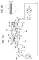
- Fig. 1A is a typical sectional side elevation schematically illustrating the constitution of an ink-jet printing apparatus to which the present invention is applied.
- Fig. 1B is an enlarged view of a portion of a conveyor belt in Fig. 1A.
- Fig. 2 is a perspective view typically illustrating a printer section and a conveyance section in the apparatus shown in Fig. 1A.
- Fig. 3 is a typical perspective view of an ink-feeding system in the apparatus shown in Fig. 1A.
- Fig. 4 is a perspective view schematically illustrating the constitution of a printing head to be mounted on the apparatus shown in Fig. 1A.
- Fig. 5 is a graph illustrating a comparison between gradation and penetration of ink in a cloth.
- According to the ink-jet printing method based on the present invention, textile printing can be performed with excellent gradation in addition to excellent coloring ability and resistance to bleeding.
- Although the above-described method of the prior art technique that "a surfactant is contained in fiber to absorb inks in the interior of the fiber by diffusion" can improve sharp bleeding to some extent, but does not achieve effective absorption of light by dyes because the dyes penetrate into the interior of the fiber, and hence can provide only a print poor in coloring ability.
- To the contrary, according to the method of the present invention, inks are not absorbed in the interior of the fiber, but are liable to remain on the surface of the fiber because the cloth having water absorption of at least 3 seconds, i.e., good water repellency, is used. In addition, since a shot-in ink quantity per ink upon printing of the maximum color density is controlled to at least 8.0 mg/mm², inks are shot out in a quantity sufficient to fill up a solid area. It is therefore considered that coloring ability is much improved.
- On the other hand, when a shot-in ink quantity is lessened upon expressing low color depth, the spread of dots is also lessened because the cloth used in the technique of the present invention is hard to absorb ink, so that an area factor (a proportion of dots occupied in a unit area) is lowered, and a blank area hence becomes greater. Therefore, a color density becomes low, thereby achieving excellent reproducibility in low color density.
- Even if a shot-in ink quantity is lessened to express low color depth in the cloth of the type that inks are absorbed in the interior of the fiber, the area factor is not lowered because of wide spread of dots, and a blank area hence becomes lessened, resulting in poor reproducibility in low color density.
- Accordingly, in the present invention, gradation expressibility from low color density area to high color density area is excellent, whereas both gradation and coloring ability are poor in the prior art techniques.
- The present invention will now be described in more detail by preferred embodiments.
- No particular limitation is imposed on the fiber material for the ink-jet printing cloth used in the present invention. Examples thereof include various fiber materials such as cotton, silk, wool, nylon, polyester, rayon and acrylic fibers. The cloth used may be a blended fabric or union cloth thereof.
- The water absorption, which is an important factor in the present invention, was determined by measuring the water absorption time using, as a measuring means, a method (dropping method) prescribed by JIS L-1096 A.
- Various methods are considered as a method of controlling the absorption of ink into cloth, i.e., penetrability.
- As a method of controlling the penetration of the ink into the cloth, there is a method in which an antipenetrant is contained in fiber. In this case, the antipenetrant means a substance which lowers the permeability of a cloth when added in a certain amount to the cloth as compared with the cloth before its addition. As specific examples of the method for containing the antipenetrant, there are considered various methods such as a method in which a softening water repellent or a water repellent is contained, a method in which a cationic substance is contained, a method in which interstices among fibers are filled in by oil, fat, wax, pigment, rubber, plastic or the like. Any of these methods may be used. However, the method making use of the softening water repellent or the water repellent is particularly preferred.
- As a method of containing the above-described antipenetrant in the cloth, any method such as padding, spraying, dipping, printing or ink-jet may be used.
- The above method will be described in more detail.
- The softening water repellent or the water repellent used for controlling the penetration of ink has the ability to repel water which is a main component of ink. Examples thereof include fluorine-containing compounds, paraffinic compounds, pyridinium salts, N-methylolalkylamides, alkylethyleneureas, oxazoline derivatives, silicone compounds, triazine compounds, polyamide amine type softening agent paraffins, zirconium compounds and mixtures thereof, to which, however, is not limited. Of these, fluorine-containing compounds and paraffinic compounds are particularly preferred.
- The water repellent is applied in an amount of from 0.1 to 10 % by weight to a cloth so as to control the water absorption time of the cloth to at least 3 seconds, preferably within a range of from 10 seconds to 200 seconds. If the water absorption time is shorter than 3 seconds, the effect of controlling the penetration of ink becomes insufficient. When a cloth having water absorption of at least 3 seconds is used, inks are not absorbed in the interior of the fiber, but tend to remain on the surface of the fiber, and so the color density on the surface becomes high. Besides, when the water absorption is controlled to at most 200 seconds, the inks moderately penetrate in the interior of the fiber, and so excellent drying ability can be achieved.
- Examples of the cationic substance used for controlling the penetration of ink include various amine salts, quaternary ammonium salt type cationic surfactants, quaternary ammonium salt polymers and polyamines.
- The cationic substance is applied in an amount of from 0.1 to 10 % by weight to a cloth so as to control the water absorption time of the cloth to at least 3 seconds, preferably within a range of from 10 seconds to 200 seconds.
- Specific examples of the oil, fat, wax, pigment, rubber and plastic used for controlling the penetration of ink include mineral oils, fatty acids, paraffin wax, silica powder, diatomaceous earth, natural rubber, olefin polymers and acrylic polymers. Such an agent is applied in an amount of from 0.1 to 10 % by weight to a cloth so as to control the water absorption time of the cloth to at least 3 seconds, preferably within a range of from 10 seconds to 200 seconds.
- The cloth according to the present invention contains the above-described substances for the purpose of controlling its water absorption, but may also contain compounds other than these substances. Examples of compounds, which may be added to the cloth of the present invention, include catalysts, alkalis, acids, antireductants, antioxidants, level dyeing agents, deep dyeing agents, carriers, reducing agents, oxidizing agents and metal ions.
- After conducting the treatment in which the antipenetrant as described above is applied to a cloth, the thus-treated cloth is finally dried and optionally cut into sizes conveyable in an ink-jet apparatus, thereby providing these cut pieces as ink-jet printing cloths.
- No particular limitation is imposed on textile printing inks used for the ink-jet printing cloths in the present invention. However, when the cloth is formed of a material such as cotton or silk, ink-jet textile printing inks composed of a reactive dye and an aqueous medium are preferably used. When the cloth is formed of a material such as nylon, wool, silk or rayon, ink-jet textile printing inks composed of an acid or direct dye and an aqueous medium are preferably used. Besides, when the cloth is formed of a polyester material, ink-jet textile printing inks composed of a disperse dye and an aqueous medium are preferably used.
- As specific preferable examples of these dyes, may be mentioned the following dyes. The reactive dyes include C.I. Reactive Yellow 2, 15, 37, 42, 76, 95, 168 and 175; C.I.
Reactive Red 21, 22, 24, 33, 45, 111, 112, 114, 180, 218, 226, 228 and 235; C.I.Reactive Blue Reactive Orange 5, 12, 13, 35 and 95; C.I.Reactive Brown 7, 11, 33, 37 and 46; C.I.Reactive Green 8 and 19; C.I. Reactive Violet 2, 6 and 22; C.I. Reactive Black 5, 8, 31 and 39; and the like. - The acid and direct dyes include C.I.
Acid Yellow Direct Black - The disperse dyes include C.I. Disperse Yellow 3, 5, 7, 33, 42, 60, 64, 79, 104, 160, 163 and 237; C.I. Disperse Red 1, 60, 135, 145, 146 and 191; C.I. Disperse
Blue 56, 60, 73, 143, 158, 198, 354, 365 and 366; C.I. Disperse Black 1 and 10; C.I. DisperseOrange 30 and 73; Teraprint Red 3GN Liquid and Teraprint Black 2R; and the like. - The amount (in terms of solids) of these dyes to be used is preferably within a range of from 1 to 30 % by weight based on the total weight of the ink.
- As water-soluble solvents used together with the dyes, those generally used in ink-jet printing inks may be used. Preferable examples thereof include lower alkylene glycols such as ethylene glycol, diethylene glycol, triethylene glycol and propylene glycol; lower alkyl ethers of alkylene glycols, such as ethylene glycol methyl (ethyl, propyl or butyl) ether, diethylene glycol methyl (ethyl, propyl or butyl) ether, triethylene glycol methyl (ethyl, propyl or butyl) ether, propylene glycol methyl (ethyl, propyl or butyl) ether, dipropylene glycol methyl (ethyl, propyl or butyl) ether and tripropylene glycol methyl (ethyl, propyl or butyl) ether; polyalkylene glycols such as polyethylene glycol and polypropylene glycol and products obtained by modifying one or two hydroxyl groups thereof, typified by mono- or dialkyl ethers thereof; glycerol; thiodiglycol; sulfolane; N-methyl-2-pyrrolidone; 2-pyrrolidone; and 1,3-dimethyl-2-imidazolidinone. The preferable content of these water-soluble solvents is generally within a range of from 0 to 50 % by weight based on the total weight of the ink.
- In the case of a water-based ink, the content of water as a principal component is preferably within a range of from 30 to 95 % by weight based on the total weight of the ink.
- Besides the above components, anti-clogging agents such as urea and derivatives thereof, dispersants, surfactants, viscosity modifiers such as polyvinyl alcohol, cellulosic compounds and sodium alginate, pH adjustors, optical whitening agents, mildewproofing agents, and the like may be added as other ingredients for inks as needed.
- As an ink-jet recording method and apparatus used, there may be used any method and apparatus conventionally known. Examples thereof include a method and an apparatus in which thermal energy corresponding to recording signals is applied to an ink within a recording head, and ink droplets are generated by this thermal energy.
- With respect to the method for expressing gradation, may be mentioned a method of controlling the diameter of a dot as a multi-valued technique, and a dither method or an error diffusion method as a two-valued technique. These methods have individual features, but each permit the expression of halftone by changing a shot-in ink quantity (weight) per unit area.
- In Fig. 5, there is shown recorded densities (K/S) obtained by using a cloth (A) the water absorption of which is at least 3 seconds as determined by the method of JIS L-1096 A and changing a shot-in ink quantity per unit area of the cloth in accordance with the dither method. For the sake of comparison, recorded densities as to a cloth (B) the water absorption of which is 1 second are also shown.
- In the cloth A, the recorded density increases in substantial proportion to the shot-in ink quantity per unit area of the cloth. Therefore, excellent gradation is achieved from low color density to high color density. On the other hand, in the cloth B, the recorded density no more increases after the shot-in ink quantity reaches a certain amount or more. This is attributable to the fact that since the cloth B is permeable as demonstrated by the water absorption of 1 second, the ink more penetrates in the thicknesswise direction of the cloth as the shot-in ink quantity increases, and so coloring cannot be effectively conducted, whereas the cloth A is hydrophobic as demonstrated by the water absorption of at least 3 seconds, and so the ink does not very penetrate in the thicknesswise direction of the cloth, but remains on the surface of the cloth, whereby excellent coloring effect can be achieved.
- A shot-in ink quantity upon printing of the maximum color density is preferably not less than 8.0 mg/mm² but not more than 35.0 mg/mm² per ink. If the shot-in ink quantity is not less than 8.0 mg/mm², an area of a cloth to be printed can be substantially filled in with ink droplets, and so high color density can be achieved. On the other hand, if the shot-in ink quantity is not more than 35.0 mg/mm², the ink is sufficiently absorbed without running, and so no bleeding occurs. The shot-in ink quantity is most preferably within a range of from 10.0 mg/mm² to 20.0 mg/mm².
- The inks applied onto the ink-jet printing cloth in accordance with the method of the present invention in the above-described manner only adhere to the cloth in this state. Accordingly, it is preferable to subsequently subject the cloth to a process for fixing the dyes in the inks to fiber and a process for removing unfixed dyes. Such a fixing process may be conducted in accordance with any conventionally-known method. Examples thereof include a steaming process, an HT steaming process and a thermofix process. The removal of the unfixed dyes may be performed by any washing process conventionally known.
- After conducting the ink-jet printing and the post-treatment of the cloth in the above-described manner, the cloth is dried to provide a print according to the present invention.
- An exemplary constitution of an ink-jet printing apparatus used in the present invention will hereinafter be roughly described. It goes without saying that the apparatus to which the present invention can be applied is not limited to the construction as described below. It is therefore possible to make any change in construction and add any structural element, which are easily conceived by those skilled in the art.
- Fig. 1A is a typical sectional side elevation schematically illustrating the construction of a printing apparatus. Reference numeral 1 designates a cloth as a printing medium. The cloth 1 is unwound according to the rotation of a
rewind roller 11, conveyed in a substantially horizontal direction by aconveyance section 100, which is provided at a position opposite to aprinter section 1000, throughintermediate rollers roller 21 through afeed roller 17 and anintermediate roller 19. - The
conveyance section 100 roughly includesconveyance rollers printer section 1000 viewing from the feeding direction of the cloth 1, aconveyor belt 130 in the form of an endless belt, which is extended between and around these rollers, and a pair ofplaten rollers 140 provided so as to extend theconveyor belt 130 under an appropriate tension in a predetermined range to enhance its evenness, thereby evenly regulating the surface of the cloth 1 to be printed by theprinter section 1000. In the illustrated apparatus, theconveyor belt 130 is made of a metal as disclosed in Japanese Patent Application Laid-Open No. 5-212851. As illustrated in Fig. 1B with partial enlargement, an adhesive layer (sheet) 133 is provided on its surface. The cloth 1 is adhered to theconveyor belt 130 through theadhesive layer 133 by an attachingroller 150, thereby ensuring the evenness of the cloth 1 upon printing. - To the cloth 1, conveyed in a state such that the evenness has been ensured as described above, is applied a printing agent in the region between the
platen rollers 140 by theprinter section 1000. The thus-printed cloth 1 is separated from theconveyor belt 130, or theadhesive layer 133 at the position of theconveyance roller 120 and wound up on the take-uproller 21. In the course of the winding, the cloth is subjected to a drying treatment by a dryingheater 600. In particular, this dryingheater 600 is effective when a liquid agent is used as the printing agent. The form of the dryingheater 600 may be suitably selected from a heater by which hot air is blown on the cloth 1, a heater by which infrared rays are applied to the cloth 1, and the like. - Fig. 2 is a perspective view typically illustrating the
printer section 1000 and the conveyance system of the cloth 1. The constitution of theprinter section 1000 will be described with reference to this drawing and Fig. 1A. - In Figs. 1A and 2, the
printer section 1000 includes acarriage 1010 which scans in a direction different from the conveying direction (a secondary scanning direction) f of the cloth 1, for example, the width direction S of the cloth 1 perpendicular to the conveying direction f.Reference numeral 1020 designates a support rail extending in the S direction (a main scanning direction) and supporting aslide rail 1022 which supports and guides aslider 1012 fixed to thecarriage 1010.Reference numeral 1030 indicates a motor as a drive source for conducting the main scanning of thecarriage 1010. The driving power thereof is transmitted to thecarriage 1010 through abelt 1032 to which thecarriage 1010 has been fixed, or another suitable drive mechanism. - On the
carriage 1010, are mounted sets ofprinting heads 1100 each having many printing agent-applying elements arranged in a predetermined direction (in this case, the conveying direction f), said sets each being composed of a plurality of the printing heads 1100 arranged in a direction (in this case, the main scanning direction S) different from said predetermined direction. In this embodiment, two sets of the printing heads 1100 are held in the conveying direction. In each set, the printing heads 1100 are provided in a number corresponding to the number of printing agents of different colors, thereby permitting color printing. Colors of the printing agents and the number of the printing heads in each set may be suitably selected according to an image intended to be formed on the cloth 1, and the like. For example, yellow (Y), magenta (M) and cyan (C), or the three primary colors for printing, or black (Bk) in addition to these colors may make one set. Alternatively, special colors (metallic colors such as gold and silver, and bright red, blue, etc.), which are impossible or difficult to be expressed by the three primary colors, may be used in place of or in addition to the above color set. Further, a plurality of printing agents may be used according to their color density even if they have the same colors as each other. - In this embodiment, as illustrated in Fig. 1A, two sets of the printing heads 1100, which each are composed of plural printing heads arranged in the main scanning direction S, are provided one by one in the conveying direction f. The colors, arranging number, arranging order and the like of the printing agents used in the printing heads in the respective sets may be the same or different from each other according to the image intended to be printed, and the like. Further, printing may be made again by the printing heads of the second set on a region printed by main scanning of the printing heads of the first set (either complementary thinning-out printing or overlap printing may be conducted by the respective sets of the printing heads). Furthermore, a printing region may be allotted to each set to perform high-speed printing. Besides, the number of sets of the printing heads is not limited to two and may also be defined as one or more than two.
- In these drawings, ink-jet heads, for example, bubble jet heads proposed by Canon Inc., each having a heating element which generates thermal energy causing film boiling of ink as energy used for ejecting the ink, are used as the printing heads 1100. Each of the printing heads is used in a state that ink ejection orifices as the printing agent-applying elements have been disposed downward toward the cloth 1 substantially horizontally conveyed by the
conveyance section 100, thereby ironing out the difference in water head between the individual ejection orifices and hence making ejection conditions uniform to permit both formation of good images and even purging operation for all the ejection orifices. - A
flexible cable 1110 is connected to each of the printing heads 1100 in such a manner that it follows the movement of thecarriage 1010, so that various signals such as drive signals and state signals for the head are transferred between the head and control means not illustrated. Inks are fed from an ink-feeding system 1130, in which respective inks of different colors are contained, to the printing heads 1100 throughflexible tubes 1120. - Fig. 3 is a perspective view typically illustrating the ink-feeding system in this embodiment. The ink-
feeding system 1130 is composed of two lines. More specifically, in the first line, first ink-feedingtubes 1120 respectively connected to the first set of ink-storage tanks 1131 are connected to a head joint 1150 through theflexible tube 1110. In the second line, similarly, second ink-feedingtubes 1121 respectively connected to the second set of ink-storage tanks 1132 are connected to the head joint 1150 through theflexible tube 1110. - Each ink-feeding
tube tube tube - The ink-
storage tanks tank tube ink connecter 1105 as illustrated in Fig. 3, circulate through theprinting head 1100 and then pass through the inward ink-feedingtube storage tank - By this pressure pump, it is possible to recharge the inks into the ink-feeding
tubes storage tanks - The number of the ink-storage tanks in each set may be suitably selected according to an image intended to be formed on the cloth 1, and the like. For example, three tanks for yellow (Y), magenta (M) and cyan (C) colors, or the three primary colors for printing, or four tanks with a tank for a black (Bk) color added to these tanks may be provided. Alternatively, tanks for special colors (metallic colors such as gold and silver, and bright red, blue, etc.), which are impossible or difficult to be expressed by the three primary colors, may be used in place of or in addition to the above tanks. Further, a plurality of tanks may be used according to the color density even if printing agents used have the same colors as each other.
- The head joint 1150 is composed of a head joint 1151 for the first set indicated by a full line in Fig. 3, a head joint 1152 for the second set indicated by a broken line in Fig. 3 and a
joint cover 1160. - The constitution of the heads used in the above-described apparatus will hereinafter be described schematically with reference to Fig. 4.
- Fig. 4 is a sectional perspective view schematically illustrating the construction of an ink-jet head to be mounted on the ink-jet printing apparatus used in the present invention.
- In this drawing, the printing head is constructed by overlapping a
top plate 71 and abase plate 72. Thetop plate 71 has a plurality ofgrooves 73, which are to define nozzles passing an ink therethrough, agroove 74, which is to define a common liquid chamber communicating with these grooves, and afeed opening 75 for feeding the ink to the common liquid chamber. On the other hand, thebase plate 72 includeselectrothermal converters 76 corresponding to the individual nozzles and electrodes 77 for supplying electric power to theelectrothermal converters 76, respectively, said electrothermal converters and electrodes being formed integrally by a film-forming technique. Ejection openings (orifices) 78 through which the ink is ejected are defined by overlapping thetop plate 71 and thebase plate 72 as described above. - Here, the process of forming ink droplets by the bubble jet system, which is carried out by the above-described printing head, will be described simply.
- When a heating resistor (heater) reaches a predetermined temperature, such a filmy bubble as covers a heater surface is first formed. The internal pressure of this bubble is very high, and so an ink within a nozzle is forced out. The ink is moved toward the outside of the nozzle and the interior of the common liquid chamber by inertia force by this forcing out. When the movement of the ink is facilitated, the moving speed of the ink within the nozzle becomes slow because the internal pressure of the bubble turns negative pressure, and flow path resistance also arises in addition. Since the ink portion ejected out of the ejection opening (orifice) is faster in moving speed than the ink within the nozzle, it is constricted by the balance among inertia force, flow path resistance, shrinkage of the bubble and surface tension of the ink, whereby the ink portion is separated into a droplet. At the same time as the shrinkage of the bubble, the ink is fed to the nozzle from the common liquid chamber by capillary force to wait for the next pulse.
- As described above, the printing head (hereinafter may be referred to as an ink-jet head), in which the electrothermal converter is used as an energy-generating means (hereinafter may be referred to as an energy-generating element), can generate a bubble in the ink within the flow path in one-to-one correspondence in accordance with a driving electrical pulse signal and also immediately and appropriately cause the growth/shrinkage of the bubble, and so the ejection of ink droplets can be achieved with excellent responsiveness in particular. The printing head is advantageous in that it can also be made compact with ease, merits of IC techniques and macro processing techniques in the recent semiconductor field, which are remarkable for advances in technique and enhancement in reliability, can be fully applied thereto, high-density mounting can be achieved with ease, and production costs are also low.
- The present invention will hereinafter be described more specifically by the following examples and comparative examples. Incidentally, all designations of "part" or "parts" and "%" as will be used in the following examples mean part or parts by weight and % by weight unless expressly noted.
- A 100 % cotton satin fabric (mercerized product), a 100 % nylon taffeta fabric and a 100 % polyester tropical fabric were separately subjected to a pretreatment with their corresponding pretreatment agents shown in Table 1 by the padding process. The thus-pretreated fabrics were then squeezed to a pickup of 70 % by a mangle and dried at a drying temperature of 120°C for 2 minutes.
- Reactive dye inks, acid dye inks and disperse dye inks were prepared in the following manner. The total amounts of the inks are all 100 parts.
(1) Reactive dye inks: Reactive dye 10 parts Thiodiglycol 40 parts Water 50 parts. - Dyes used were C.I. Reactive Yellow 95, C.I. Reactive Red 226, C.I.
Reactive Blue 15 and C.I. Reactive Black 39.(2) Acid dye inks: Acid dye 10 parts Diethylene glycol 40 parts Water 50 parts. - Dyes used were C.I.
Acid Yellow 110, C.I. Acid Red 266, C.I. Acid Blue 90 and C.I. Acid Black 26.(3) Disperse dye inks: Disperse dye 10 parts Thiodiglycol 40 parts Water 50 parts. - Dyes used were C.I. Disperse Yellow 42, Teraprint Red 3GN Liquid (trade name, a disperse dye produced by Ciba-Geigy AG) and Teraprint Black 2R (trade name, a disperse dye produced by Ciba-Geigy AG). These disperse dye inks each contained a dispersant for dispersing the dye.
- Using a Bubble Jet Printer BJC-820J (manufactured by Canon Inc.), in which heads each ejecting 84 ng of ink were mounted, as an ink-jet printing apparatus, sets of the above-prepared printing inks were separately charged in this printer. The fabrics were separately mounted on base paper webs to permit the conveying of the fabrics, thereby conducting printing (the maximum shot-in ink quantity per ink: 17 mg/mm²). Any printing apparatus may be used without limitation to the above printing apparatus.
- Each 20 x 20 mm square pattern was printed with the shot-in ink quantity per unit area of the fabric varied in the order of 2, 8 and 17 mg/mm² according to the dither method.
- The printed fabrics were subjected to a steaming treatment at 100°C for 8 minutes for the reactive dye inks, at 100°C for 30 minutes for the acid dye inks, or at 180°C for 10 minutes for the disperse dye inks. The thus-treated fabrics were washed and then dried.
- The thus-obtained print samples were evaluated in the following manner. The results are shown in Table 1.
- The linearity of fine-line portions in each print sample was visually observed to rank resistance to bleeding in accordance with the following standard:
- A:
- Good;
- B:
- Somewhat poor;
- C:
- Poor.
- Minimum spectral reflectances of printed areas of the 20 x 20 mm square pattern in each print sample were measured by a Minolta Spectrocolorimeter CM-2022 (trade name). Respective K/S values were found from these reflectances. The maximum color density was ranked in terms of the K/S values in shot-in ink quantities per unit area of 8 and 17 mg/mm² in accordance with the following standard:
- A:
- At least 15;
- C:
- Smaller than 15.
- Minimum spectral reflectances of printed areas of the 20 x 20 mm square pattern in each print sample were measured by the Minolta Spectrocolorimeter CM-2022. Respective K/S values were found from these reflectances. The gradation was ranked in terms of ratios of the K/S value in the shot-in ink quantity per unit area of 8 mg/mm² to the K/S value in 2 mg/mm² and of the K/S value in the shot-in ink quantity per unit area of 17 mg/mm² to the K/S value in 2 mg/mm² in accordance with the following standard:
- A:
- At least 8;
- C:
- Smaller than 8.
- Ink-jet printing and evaluation were conducted in the same manner as in Examples 1 to 13 except that the cloths, the pretreatment agents and the textile printing inks were changed to those shown in Table 2. The results are shown in Table 2.


- As apparent from Tables 1 and 2, all the prints according to Examples 1 to 13 were free of bleeding, high in maximum color density and also excellent in gradation, whereas the prints according to Comparative Examples 1 to 15 were low in maximum color density and also poor in gradation because the K/S value by no means reached 15.
- In the prints obtained in Examples 1 to 13, the shot-in ink quantities per unit area of the fabric at mixed-color areas (


- As described above, the ink-jet printing processes according to the present invention permit the provision of bright prints free of bleeding, high in color depth, excellent in gradation and high in image quality.
- While the present invention has been described with respect to what is presently considered to be the preferred embodiments, it is to be understood that the invention is not limited to the disclosed embodiments. To the contrary, the invention is intended to cover various modifications and equivalent arrangements included within the spirit and scope of the appended claims. The scope of the following claims is to be accorded the broadest interpretation so as to encompass all such modifications and equivalent structures and functions.
- Disclosed herein is an ink-jet printing method comprising ejecting inks by an ink-jet printing apparatus to conduct printing on a cloth, wherein a cloth having water absorption of at least 3 seconds as determined by a method (dropping method) prescribed by JIS L-1096 A is used as said cloth, a shot-in ink quantity per unit area of the cloth is changed to conduct gradation control, and a shot-in ink quantity per ink upon printing of the maximum color density is adjusted within a range of from not less than 8.0 mg/mm² to not more than 35.0 mg/mm².
Claims (6)
- An ink-jet printing method comprising ejecting inks by an ink-jet printing apparatus to conduct printing on a cloth, wherein a cloth having water absorption of at least 3 seconds as determined by a method (dropping method) prescribed by JIS L-1096 A is used as said cloth, a shot-in ink quantity per unit area of the cloth is changed to conduct gradation control, and a shot-in ink quantity per ink upon printing of the maximum color density is adjusted within a range of from not less than 8.0 mg/mm² to not more than 35.0 mg/mm².
- The ink-jet printing method according to Claim 1, wherein at least one of a water repellent and a softening water repellent is applied to the cloth.
- The ink-jet printing method according to Claim 2, wherein the water repellent is selected from the group consisting of fluorine-containing compounds, paraffinic compounds, pyridinium salts, N-methylolalkylamides, alkylethyleneureas, oxazoline derivatives, silicone compounds, triazine compounds, polyamide amine type softening agent paraffins and zirconium compounds.
- The ink-jet printing method according to Claim 2, wherein the water repellent is applied in an amount of from 0.1 to 10 % by weight based on the cloth.
- The ink-jet printing method according to Claim 1, wherein the ink-jet printing apparatus comprises an electrothermal converter, which generates thermal energy causing film boiling of ink, as an energy-generating means for ejecting the inks.
- A print obtained by the method according to any one of Claims 1 to 5.
Priority Applications (1)
| Application Number | Priority Date | Filing Date | Title |
|---|---|---|---|
| EP02000451A EP1215333A3 (en) | 1994-10-25 | 1995-10-24 | Ink-jet printing method and print |
Applications Claiming Priority (6)
| Application Number | Priority Date | Filing Date | Title |
|---|---|---|---|
| JP26005994 | 1994-10-25 | ||
| JP260059/94 | 1994-10-25 | ||
| JP26005994 | 1994-10-25 | ||
| JP27135295 | 1995-10-19 | ||
| JP271352/95 | 1995-10-19 | ||
| JP7271352A JPH08176973A (en) | 1994-10-25 | 1995-10-19 | Ink-jet printing and printed product |
Related Child Applications (2)
| Application Number | Title | Priority Date | Filing Date |
|---|---|---|---|
| EP02000451A Division EP1215333A3 (en) | 1994-10-25 | 1995-10-24 | Ink-jet printing method and print |
| EP02000451.1 Division-Into | 2002-01-08 |
Publications (2)
| Publication Number | Publication Date |
|---|---|
| EP0709519A1 true EP0709519A1 (en) | 1996-05-01 |
| EP0709519B1 EP0709519B1 (en) | 2003-04-09 |
Family
ID=26544430
Family Applications (2)
| Application Number | Title | Priority Date | Filing Date |
|---|---|---|---|
| EP95116762A Expired - Lifetime EP0709519B1 (en) | 1994-10-25 | 1995-10-24 | Ink-jet printing method and print |
| EP02000451A Withdrawn EP1215333A3 (en) | 1994-10-25 | 1995-10-24 | Ink-jet printing method and print |
Family Applications After (1)
| Application Number | Title | Priority Date | Filing Date |
|---|---|---|---|
| EP02000451A Withdrawn EP1215333A3 (en) | 1994-10-25 | 1995-10-24 | Ink-jet printing method and print |
Country Status (6)
| Country | Link |
|---|---|
| US (1) | US6224204B1 (en) |
| EP (2) | EP0709519B1 (en) |
| JP (1) | JPH08176973A (en) |
| CN (1) | CN1075981C (en) |
| AT (1) | ATE237020T1 (en) |
| DE (1) | DE69530262D1 (en) |
Cited By (9)
| Publication number | Priority date | Publication date | Assignee | Title |
|---|---|---|---|---|
| EP0805230A2 (en) * | 1996-05-02 | 1997-11-05 | Canon Kabushiki Kaisha | Ink-jet printing process and print |
| WO2006100279A1 (en) * | 2005-03-22 | 2006-09-28 | Ten Cate Advanced Textiles B.V. | Method for providing a water-repellent finish on a textile article |
| US20070103529A1 (en) * | 2003-06-16 | 2007-05-10 | Kornit Digital Ltd. | Process and system for printing images on absorptive surfaces |
| US9611401B2 (en) | 2009-08-10 | 2017-04-04 | Kornit Digital Ltd. | Inkjet compositions and processes for stretchable substrates |
| US9616683B2 (en) | 2010-08-10 | 2017-04-11 | Kornit Digital Ltd. | Formaldehyde-free inkjet compositions and processes |
| CN110849249A (en) * | 2019-11-28 | 2020-02-28 | 湖南浚林服饰有限公司 | Sewing position roughness and tensile strength detection device that pulls |
| US11098214B2 (en) | 2016-10-31 | 2021-08-24 | Kornit Digital Ltd. | Dye-sublimation inkjet printing for textile |
| US11447648B2 (en) | 2004-05-30 | 2022-09-20 | Kornit Digital Ltd. | Process and system for printing images on absorptive surfaces |
| US11629265B2 (en) | 2017-10-22 | 2023-04-18 | Kornit Digital Ltd. | Low-friction images by inkjet printing |
Families Citing this family (20)
| Publication number | Priority date | Publication date | Assignee | Title |
|---|---|---|---|---|
| US6428159B1 (en) * | 1999-07-19 | 2002-08-06 | Xerox Corporation | Apparatus for achieving high quality aqueous ink-jet printing on plain paper at high print speeds |
| US6588954B2 (en) * | 2000-02-23 | 2003-07-08 | Agfa-Gevaert | Ink jet printer equipped for avoiding undesired belt movement |
| US6561642B2 (en) | 2001-09-28 | 2003-05-13 | Hewlett-Packard Development Company | Ink jet printer system for printing an image on a web overlaying a removable substrate and method of assembling the printer system |
| US20040202801A1 (en) * | 2003-04-09 | 2004-10-14 | Milliken & Company | Products and compositions employed in solvent-based ink jet printing |
| US6846076B2 (en) * | 2003-04-09 | 2005-01-25 | Milliken & Company | Methods employed in solvent-based ink jet printing |
| WO2004094149A2 (en) * | 2003-04-09 | 2004-11-04 | Milliken & Company | Products, compositions, and methods employed in solvent-based ink jet printing |
| EP1624034B1 (en) * | 2003-05-02 | 2011-06-15 | Canon Kabushiki Kaisha | Aqueous fluorescent ink, recorded image using same, and judging method |
| US20040248492A1 (en) * | 2003-06-06 | 2004-12-09 | Reemay, Inc. | Nonwoven fabric printing medium and method of production |
| WO2006001546A1 (en) * | 2004-06-28 | 2006-01-05 | Canon Kabushiki Kaisha | Method for producing dispersible colorant and ink for inkjet recording |
| ES2351944T3 (en) * | 2007-10-31 | 2011-02-14 | Xennia Holland Bv | PROVISION OF PRINTING HEADS AND PROCEDURE FOR THE DEPOSITION OF A SUBSTANCE. |
| JP5453681B2 (en) * | 2010-02-12 | 2014-03-26 | 株式会社ミマキエンジニアリング | Image forming apparatus and image forming method |
| CN102490466B (en) * | 2011-12-06 | 2016-06-08 | 江南大学 | The fixed dull and stereotyped digital inkjet printing machine of a kind of hyperchannel head |
| CN102514374B (en) * | 2011-12-06 | 2016-04-13 | 江南大学 | A kind of two jet head sets flat plate type digital ink-jetting printing machines |
| JP6194674B2 (en) * | 2013-07-29 | 2017-09-13 | セイコーエプソン株式会社 | Recording device |
| CN103935132B (en) * | 2014-05-04 | 2016-05-04 | 长沙湘愿节能科技有限公司 | A kind of two-way linkage seven look stand alone type high speed ink-jet decorating machines |
| CN105500924B (en) * | 2016-02-14 | 2017-01-18 | 江南大学 | Three-roller drive digital inkjet printing machine |
| CN105538929B (en) * | 2016-02-14 | 2017-12-08 | 绍兴悦植贸易有限公司 | A kind of more slab conduction band type digital inkjet printing devices and printing method |
| CN106995152B (en) * | 2017-05-16 | 2019-02-22 | 嘉兴市前荣织造有限公司 | A kind of spray printing device of textile printing and dyeing cloth |
| JP2019025854A (en) * | 2017-08-02 | 2019-02-21 | 株式会社ミマキエンジニアリング | Printer, manufacturing method of printed matter and printed matter |
| CN109808322B (en) * | 2019-02-26 | 2021-02-26 | 浙江金晨纺织科技有限公司 | Gravure printing method for heat transfer paper |
Citations (4)
| Publication number | Priority date | Publication date | Assignee | Title |
|---|---|---|---|---|
| JPH0459282A (en) | 1990-06-28 | 1992-02-26 | Toray Ind Inc | Ink jet dying cloth and ink jet dying method using the same |
| JPH05195448A (en) * | 1991-11-01 | 1993-08-03 | Kanebo Ltd | Printed fabric |
| EP0605730A1 (en) * | 1992-07-27 | 1994-07-13 | Kanebo, Ltd. | Printed cloth and method of manufacturing the same |
| EP0613288A2 (en) * | 1993-01-29 | 1994-08-31 | Canon Kabushiki Kaisha | Image supply apparatus, image output apparatus, control apparatus therefor, and image forming system having these apparatuses |
Family Cites Families (6)
| Publication number | Priority date | Publication date | Assignee | Title |
|---|---|---|---|---|
| GB2187137B (en) * | 1986-02-07 | 1990-10-17 | Canon Kk | Recording medium and recording method which makes use thereof |
| JP2713685B2 (en) * | 1991-12-27 | 1998-02-16 | キヤノン株式会社 | Ink-jet printing method, fabric printed by the same method, and method for producing printed fabric |
| JP2952128B2 (en) * | 1992-01-27 | 1999-09-20 | キヤノン株式会社 | Fabric for inkjet printing, inkjet printing method and printed matter |
| JP2736484B2 (en) | 1992-02-05 | 1998-04-02 | 鐘紡株式会社 | Printing equipment |
| US5515093A (en) * | 1993-06-25 | 1996-05-07 | Canon Kabushiki Kaisha | Ink jet printing method and print medium for use in the method |
| US5867197A (en) * | 1994-07-21 | 1999-02-02 | Canon Kabushiki Kaisha | Ink-jet printing cloth, ink-jet printing process and production process of print |
-
1995
- 1995-10-19 JP JP7271352A patent/JPH08176973A/en active Pending
- 1995-10-24 DE DE69530262T patent/DE69530262D1/en not_active Expired - Lifetime
- 1995-10-24 AT AT95116762T patent/ATE237020T1/en not_active IP Right Cessation
- 1995-10-24 EP EP95116762A patent/EP0709519B1/en not_active Expired - Lifetime
- 1995-10-24 US US08/547,463 patent/US6224204B1/en not_active Expired - Fee Related
- 1995-10-24 EP EP02000451A patent/EP1215333A3/en not_active Withdrawn
- 1995-10-25 CN CN95117659A patent/CN1075981C/en not_active Expired - Fee Related
Patent Citations (4)
| Publication number | Priority date | Publication date | Assignee | Title |
|---|---|---|---|---|
| JPH0459282A (en) | 1990-06-28 | 1992-02-26 | Toray Ind Inc | Ink jet dying cloth and ink jet dying method using the same |
| JPH05195448A (en) * | 1991-11-01 | 1993-08-03 | Kanebo Ltd | Printed fabric |
| EP0605730A1 (en) * | 1992-07-27 | 1994-07-13 | Kanebo, Ltd. | Printed cloth and method of manufacturing the same |
| EP0613288A2 (en) * | 1993-01-29 | 1994-08-31 | Canon Kabushiki Kaisha | Image supply apparatus, image output apparatus, control apparatus therefor, and image forming system having these apparatuses |
Non-Patent Citations (1)
| Title |
|---|
| DATABASE WPI Section Ch Week 9335, Derwent World Patents Index; Class F06, AN 93-278806 * |
Cited By (15)
| Publication number | Priority date | Publication date | Assignee | Title |
|---|---|---|---|---|
| EP0805230A2 (en) * | 1996-05-02 | 1997-11-05 | Canon Kabushiki Kaisha | Ink-jet printing process and print |
| EP0805230A3 (en) * | 1996-05-02 | 1998-07-08 | Canon Kabushiki Kaisha | Ink-jet printing process and print |
| US6036307A (en) * | 1996-05-02 | 2000-03-14 | Canon Kabushiki Kaisha | Ink-jet printing process and print |
| US20070103529A1 (en) * | 2003-06-16 | 2007-05-10 | Kornit Digital Ltd. | Process and system for printing images on absorptive surfaces |
| US11447648B2 (en) | 2004-05-30 | 2022-09-20 | Kornit Digital Ltd. | Process and system for printing images on absorptive surfaces |
| WO2006100279A1 (en) * | 2005-03-22 | 2006-09-28 | Ten Cate Advanced Textiles B.V. | Method for providing a water-repellent finish on a textile article |
| US11021627B2 (en) | 2009-08-10 | 2021-06-01 | Kornit Digital Ltd. | Inkjet compositions and processes for stretchable substrates |
| US10472533B2 (en) | 2009-08-10 | 2019-11-12 | Kornit Digital Ltd. | Inkjet compositions and processes for stretchable substrates |
| US9611401B2 (en) | 2009-08-10 | 2017-04-04 | Kornit Digital Ltd. | Inkjet compositions and processes for stretchable substrates |
| US11898048B2 (en) | 2009-08-10 | 2024-02-13 | Kornit Digital Ltd. | Inkjet compositions and processes for stretchable substrates |
| US9616683B2 (en) | 2010-08-10 | 2017-04-11 | Kornit Digital Ltd. | Formaldehyde-free inkjet compositions and processes |
| US11098214B2 (en) | 2016-10-31 | 2021-08-24 | Kornit Digital Ltd. | Dye-sublimation inkjet printing for textile |
| US11629265B2 (en) | 2017-10-22 | 2023-04-18 | Kornit Digital Ltd. | Low-friction images by inkjet printing |
| CN110849249A (en) * | 2019-11-28 | 2020-02-28 | 湖南浚林服饰有限公司 | Sewing position roughness and tensile strength detection device that pulls |
| CN110849249B (en) * | 2019-11-28 | 2021-12-17 | 济宁天久工贸有限公司 | Sewing position roughness and tensile strength detection device that pulls |
Also Published As
| Publication number | Publication date |
|---|---|
| ATE237020T1 (en) | 2003-04-15 |
| US6224204B1 (en) | 2001-05-01 |
| JPH08176973A (en) | 1996-07-09 |
| EP1215333A3 (en) | 2010-06-30 |
| EP0709519B1 (en) | 2003-04-09 |
| DE69530262D1 (en) | 2003-05-15 |
| CN1126666A (en) | 1996-07-17 |
| EP1215333A2 (en) | 2002-06-19 |
| CN1075981C (en) | 2001-12-12 |
Similar Documents
| Publication | Publication Date | Title |
|---|---|---|
| EP0709519A1 (en) | Ink-jet printing method and print | |
| EP0693587B1 (en) | Ink-jet printing cloth, ink-jet printing process and production process of print | |
| EP0790347B1 (en) | Ink-jet printing cloth, ink-jet printing process and print | |
| KR100392578B1 (en) | Printing Process, Print Obtained by the Process and Processed Article | |
| EP0879912B1 (en) | Method and apparatus for ink jet printing on textile products | |
| US6613821B2 (en) | Cloth treating agent, cloth, textile printing process and print | |
| JP3164868B2 (en) | Inkjet printing method | |
| EP0693588B1 (en) | Textile printing method and printed textile obtained thereby | |
| JP3315532B2 (en) | Fabric for inkjet printing, method for producing the same, inkjet printing method, inkjet printed matter, and printed recorded matter | |
| US6543869B2 (en) | Ink-jet printing apparatus and ink-jet printing method | |
| US6200667B1 (en) | Cloth for textile printing, and textile printing process using the cloth and print obtained thereby | |
| EP0790346B1 (en) | Ink-jet printing cloth, ink-jet printing process and print | |
| JP3501519B2 (en) | Fabric for inkjet printing, inkjet printing method, and inkjet printed material | |
| JPH1053973A (en) | Knitted fabric for ink jet printing, its production, ink jet printing and ink jet printed product | |
| JPH10331078A (en) | Fabric for ink jet dyeing, ink jet dyeing using the same and ink jet-dyed fabric | |
| JP2004169248A (en) | Ink jet printing method and ink jet printing apparatus | |
| JPH08127980A (en) | Fabric for ink-jet printing, ink-jet printing method and fabric printed by ink-jet | |
| JPH08127978A (en) | Fabric for ink-jet printing, ink-jet printing method and fabric printed by ink-jet |
Legal Events
| Date | Code | Title | Description |
|---|---|---|---|
| PUAI | Public reference made under article 153(3) epc to a published international application that has entered the european phase |
Free format text: ORIGINAL CODE: 0009012 |
|
| AK | Designated contracting states |
Kind code of ref document: A1 Designated state(s): AT BE CH DE DK ES FR GB GR IE IT LI LU MC NL PT SE |
|
| 17P | Request for examination filed |
Effective date: 19960617 |
|
| 17Q | First examination report despatched |
Effective date: 20000105 |
|
| GRAH | Despatch of communication of intention to grant a patent |
Free format text: ORIGINAL CODE: EPIDOS IGRA |
|
| GRAH | Despatch of communication of intention to grant a patent |
Free format text: ORIGINAL CODE: EPIDOS IGRA |
|
| GRAA | (expected) grant |
Free format text: ORIGINAL CODE: 0009210 |
|
| AK | Designated contracting states |
Designated state(s): AT BE CH DE DK ES FR GB GR IE IT LI LU MC NL PT SE |
|
| PG25 | Lapsed in a contracting state [announced via postgrant information from national office to epo] |
Ref country code: NL Free format text: LAPSE BECAUSE OF FAILURE TO SUBMIT A TRANSLATION OF THE DESCRIPTION OR TO PAY THE FEE WITHIN THE PRESCRIBED TIME-LIMIT Effective date: 20030409 Ref country code: LI Free format text: LAPSE BECAUSE OF FAILURE TO SUBMIT A TRANSLATION OF THE DESCRIPTION OR TO PAY THE FEE WITHIN THE PRESCRIBED TIME-LIMIT Effective date: 20030409 Ref country code: IT Free format text: LAPSE BECAUSE OF FAILURE TO SUBMIT A TRANSLATION OF THE DESCRIPTION OR TO PAY THE FEE WITHIN THE PRESCRIBED TIME-LIMIT;WARNING: LAPSES OF ITALIAN PATENTS WITH EFFECTIVE DATE BEFORE 2007 MAY HAVE OCCURRED AT ANY TIME BEFORE 2007. THE CORRECT EFFECTIVE DATE MAY BE DIFFERENT FROM THE ONE RECORDED. Effective date: 20030409 Ref country code: FR Free format text: LAPSE BECAUSE OF FAILURE TO SUBMIT A TRANSLATION OF THE DESCRIPTION OR TO PAY THE FEE WITHIN THE PRESCRIBED TIME-LIMIT Effective date: 20030409 Ref country code: CH Free format text: LAPSE BECAUSE OF FAILURE TO SUBMIT A TRANSLATION OF THE DESCRIPTION OR TO PAY THE FEE WITHIN THE PRESCRIBED TIME-LIMIT Effective date: 20030409 Ref country code: BE Free format text: LAPSE BECAUSE OF FAILURE TO SUBMIT A TRANSLATION OF THE DESCRIPTION OR TO PAY THE FEE WITHIN THE PRESCRIBED TIME-LIMIT Effective date: 20030409 Ref country code: AT Free format text: LAPSE BECAUSE OF FAILURE TO SUBMIT A TRANSLATION OF THE DESCRIPTION OR TO PAY THE FEE WITHIN THE PRESCRIBED TIME-LIMIT Effective date: 20030409 |
|
| REG | Reference to a national code |
Ref country code: GB Ref legal event code: FG4D |
|
| REG | Reference to a national code |
Ref country code: CH Ref legal event code: EP |
|
| REG | Reference to a national code |
Ref country code: IE Ref legal event code: FG4D |
|
| PG25 | Lapsed in a contracting state [announced via postgrant information from national office to epo] |
Ref country code: SE Free format text: LAPSE BECAUSE OF FAILURE TO SUBMIT A TRANSLATION OF THE DESCRIPTION OR TO PAY THE FEE WITHIN THE PRESCRIBED TIME-LIMIT Effective date: 20030709 Ref country code: PT Free format text: LAPSE BECAUSE OF FAILURE TO SUBMIT A TRANSLATION OF THE DESCRIPTION OR TO PAY THE FEE WITHIN THE PRESCRIBED TIME-LIMIT Effective date: 20030709 Ref country code: GR Free format text: LAPSE BECAUSE OF FAILURE TO SUBMIT A TRANSLATION OF THE DESCRIPTION OR TO PAY THE FEE WITHIN THE PRESCRIBED TIME-LIMIT Effective date: 20030709 Ref country code: DK Free format text: LAPSE BECAUSE OF FAILURE TO SUBMIT A TRANSLATION OF THE DESCRIPTION OR TO PAY THE FEE WITHIN THE PRESCRIBED TIME-LIMIT Effective date: 20030709 |
|
| PG25 | Lapsed in a contracting state [announced via postgrant information from national office to epo] |
Ref country code: DE Free format text: LAPSE BECAUSE OF FAILURE TO SUBMIT A TRANSLATION OF THE DESCRIPTION OR TO PAY THE FEE WITHIN THE PRESCRIBED TIME-LIMIT Effective date: 20030710 |
|
| NLV1 | Nl: lapsed or annulled due to failure to fulfill the requirements of art. 29p and 29m of the patents act | ||
| REG | Reference to a national code |
Ref country code: CH Ref legal event code: PL |
|
| PG25 | Lapsed in a contracting state [announced via postgrant information from national office to epo] |
Ref country code: LU Free format text: LAPSE BECAUSE OF NON-PAYMENT OF DUE FEES Effective date: 20031024 Ref country code: IE Free format text: LAPSE BECAUSE OF NON-PAYMENT OF DUE FEES Effective date: 20031024 |
|
| PG25 | Lapsed in a contracting state [announced via postgrant information from national office to epo] |
Ref country code: ES Free format text: LAPSE BECAUSE OF FAILURE TO SUBMIT A TRANSLATION OF THE DESCRIPTION OR TO PAY THE FEE WITHIN THE PRESCRIBED TIME-LIMIT Effective date: 20031030 |
|
| PG25 | Lapsed in a contracting state [announced via postgrant information from national office to epo] |
Ref country code: MC Free format text: LAPSE BECAUSE OF NON-PAYMENT OF DUE FEES Effective date: 20031031 |
|
| PLBE | No opposition filed within time limit |
Free format text: ORIGINAL CODE: 0009261 |
|
| STAA | Information on the status of an ep patent application or granted ep patent |
Free format text: STATUS: NO OPPOSITION FILED WITHIN TIME LIMIT |
|
| EN | Fr: translation not filed | ||
| 26N | No opposition filed |
Effective date: 20040112 |
|
| REG | Reference to a national code |
Ref country code: IE Ref legal event code: MM4A |
|
| PGFP | Annual fee paid to national office [announced via postgrant information from national office to epo] |
Ref country code: GB Payment date: 20081029 Year of fee payment: 14 |
|
| PG25 | Lapsed in a contracting state [announced via postgrant information from national office to epo] |
Ref country code: GB Free format text: LAPSE BECAUSE OF NON-PAYMENT OF DUE FEES Effective date: 20091024 |