EP0805065B1 - Longitudinal guide for automotive vehicle seats - Google Patents
Longitudinal guide for automotive vehicle seats Download PDFInfo
- Publication number
- EP0805065B1 EP0805065B1 EP97104376A EP97104376A EP0805065B1 EP 0805065 B1 EP0805065 B1 EP 0805065B1 EP 97104376 A EP97104376 A EP 97104376A EP 97104376 A EP97104376 A EP 97104376A EP 0805065 B1 EP0805065 B1 EP 0805065B1
- Authority
- EP
- European Patent Office
- Prior art keywords
- locking bolt
- spring
- locking
- openings
- guided
- Prior art date
- Legal status (The legal status is an assumption and is not a legal conclusion. Google has not performed a legal analysis and makes no representation as to the accuracy of the status listed.)
- Expired - Lifetime
Links
Images
Classifications
-
- B—PERFORMING OPERATIONS; TRANSPORTING
- B60—VEHICLES IN GENERAL
- B60N—SEATS SPECIALLY ADAPTED FOR VEHICLES; VEHICLE PASSENGER ACCOMMODATION NOT OTHERWISE PROVIDED FOR
- B60N2/00—Seats specially adapted for vehicles; Arrangement or mounting of seats in vehicles
- B60N2/02—Seats specially adapted for vehicles; Arrangement or mounting of seats in vehicles the seat or part thereof being movable, e.g. adjustable
- B60N2/04—Seats specially adapted for vehicles; Arrangement or mounting of seats in vehicles the seat or part thereof being movable, e.g. adjustable the whole seat being movable
- B60N2/06—Seats specially adapted for vehicles; Arrangement or mounting of seats in vehicles the seat or part thereof being movable, e.g. adjustable the whole seat being movable slidable
- B60N2/08—Seats specially adapted for vehicles; Arrangement or mounting of seats in vehicles the seat or part thereof being movable, e.g. adjustable the whole seat being movable slidable characterised by the locking device
- B60N2/0831—Movement of the latch
- B60N2/0862—Movement of the latch sliding
- B60N2/0868—Movement of the latch sliding in a transversal direction
-
- B—PERFORMING OPERATIONS; TRANSPORTING
- B60—VEHICLES IN GENERAL
- B60N—SEATS SPECIALLY ADAPTED FOR VEHICLES; VEHICLE PASSENGER ACCOMMODATION NOT OTHERWISE PROVIDED FOR
- B60N2/00—Seats specially adapted for vehicles; Arrangement or mounting of seats in vehicles
- B60N2/02—Seats specially adapted for vehicles; Arrangement or mounting of seats in vehicles the seat or part thereof being movable, e.g. adjustable
- B60N2/04—Seats specially adapted for vehicles; Arrangement or mounting of seats in vehicles the seat or part thereof being movable, e.g. adjustable the whole seat being movable
- B60N2/06—Seats specially adapted for vehicles; Arrangement or mounting of seats in vehicles the seat or part thereof being movable, e.g. adjustable the whole seat being movable slidable
- B60N2/07—Slide construction
- B60N2/0702—Slide construction characterised by its cross-section
- B60N2/0705—Slide construction characterised by its cross-section omega-shaped
-
- B—PERFORMING OPERATIONS; TRANSPORTING
- B60—VEHICLES IN GENERAL
- B60N—SEATS SPECIALLY ADAPTED FOR VEHICLES; VEHICLE PASSENGER ACCOMMODATION NOT OTHERWISE PROVIDED FOR
- B60N2/00—Seats specially adapted for vehicles; Arrangement or mounting of seats in vehicles
- B60N2/02—Seats specially adapted for vehicles; Arrangement or mounting of seats in vehicles the seat or part thereof being movable, e.g. adjustable
- B60N2/04—Seats specially adapted for vehicles; Arrangement or mounting of seats in vehicles the seat or part thereof being movable, e.g. adjustable the whole seat being movable
- B60N2/06—Seats specially adapted for vehicles; Arrangement or mounting of seats in vehicles the seat or part thereof being movable, e.g. adjustable the whole seat being movable slidable
- B60N2/07—Slide construction
- B60N2/0702—Slide construction characterised by its cross-section
- B60N2/0715—C or U-shaped
-
- B—PERFORMING OPERATIONS; TRANSPORTING
- B60—VEHICLES IN GENERAL
- B60N—SEATS SPECIALLY ADAPTED FOR VEHICLES; VEHICLE PASSENGER ACCOMMODATION NOT OTHERWISE PROVIDED FOR
- B60N2/00—Seats specially adapted for vehicles; Arrangement or mounting of seats in vehicles
- B60N2/02—Seats specially adapted for vehicles; Arrangement or mounting of seats in vehicles the seat or part thereof being movable, e.g. adjustable
- B60N2/04—Seats specially adapted for vehicles; Arrangement or mounting of seats in vehicles the seat or part thereof being movable, e.g. adjustable the whole seat being movable
- B60N2/06—Seats specially adapted for vehicles; Arrangement or mounting of seats in vehicles the seat or part thereof being movable, e.g. adjustable the whole seat being movable slidable
- B60N2/08—Seats specially adapted for vehicles; Arrangement or mounting of seats in vehicles the seat or part thereof being movable, e.g. adjustable the whole seat being movable slidable characterised by the locking device
- B60N2/0812—Location of the latch
- B60N2/0818—Location of the latch inside the rail
-
- B—PERFORMING OPERATIONS; TRANSPORTING
- B60—VEHICLES IN GENERAL
- B60N—SEATS SPECIALLY ADAPTED FOR VEHICLES; VEHICLE PASSENGER ACCOMMODATION NOT OTHERWISE PROVIDED FOR
- B60N2/00—Seats specially adapted for vehicles; Arrangement or mounting of seats in vehicles
- B60N2/02—Seats specially adapted for vehicles; Arrangement or mounting of seats in vehicles the seat or part thereof being movable, e.g. adjustable
- B60N2/04—Seats specially adapted for vehicles; Arrangement or mounting of seats in vehicles the seat or part thereof being movable, e.g. adjustable the whole seat being movable
- B60N2/06—Seats specially adapted for vehicles; Arrangement or mounting of seats in vehicles the seat or part thereof being movable, e.g. adjustable the whole seat being movable slidable
- B60N2/08—Seats specially adapted for vehicles; Arrangement or mounting of seats in vehicles the seat or part thereof being movable, e.g. adjustable the whole seat being movable slidable characterised by the locking device
- B60N2/0812—Location of the latch
- B60N2/0825—Location of the latch outside the rail
Definitions
- the invention relates to a longitudinal adjustment device for Motor vehicle seats according to the preamble of claim 1.
- Such known longitudinal adjustment devices are among others used in motor vehicles, which two pairs of side rails have and a central pair of front slide rails, the one top rail connected to the seat has, which runs on chassis-fixed rollers and in one chassis-fixed lower rail is guided or held.
- a longitudinal adjustment device in which the chassis-fixed lower rail has through openings arranged over the length for seat adjustment.
- the invention is based on the prior art mentioned at the beginning the task of a longitudinal adjustment device as known type to train so that they in Crash case is evenly loaded and secure locking enables, without this particularly large profile thicknesses required are.
- the longitudinal adjustment device according to the invention allows one even transfer of the load from the seat to the chassis.
- the top rail 2 is guided in an approximately C-shaped lower rail.
- the two Sliders 11 and 12 engage in the grooves 2f and 2g Top rail on.
- the lower rail 1 is via mounting flanges 1c attached to the vehicle floor.
- To the top pointing inside of the horizontal base leg of the lower rail 1 are parallel to each other and in the vehicle longitudinal direction vertical flange 1e and 1d welded. Is located between the two flanges 1e and 1d a transverse spacer 4 with a recess 4a.
- first Locking bolt 6a On the lower rail 1 there is a laterally transverse to the longitudinal direction extending sleeve 13 welded in the first Locking bolt 6a is mounted transversely.
- the first locking bolt 6a engages in the locking position a through opening 2a in the side leg 2e Upper rail 2.
- the through opening 2a is shown in the Embodiment in a reinforcing rail 10 Metal provided.
- a sleeve 8 is aligned, which between the vertically extending flanges 1e and 1d attached is.
- a second locking pin 6b flush with the first locking bolt 6a stored.
- the second locking bolt 6b engages in the locked state according to Figure 1 with his Front through a through opening 2b in the side leg 2d of the top rail 2.
- the second locking bolt 6b is under the action a return spring 9 designed as a compression spring Return spring 9 is supported on the one hand on an inner Collar of the sleeve 8 and on the other hand on a circumferential Bund of the second locking bolt 6b.
- the first locking bolt 6a is under the action a tension spring 5.
- the spring force of the tension spring 5 is greater than the spring force of the return spring designed as a compression spring 9. This has the consequence that the locking bolt 6a with suitably opposite through openings 2a and 2d the second locking bolt 6b in the figure 1 locking position shown presses.
- the multiple rollers 3 run on the inside of the base leg 2c of the substantially U-shaped Top rail 2 from.
Description
Die Erfindung betrifft eine Längsverstellvorrichtung für
Kraftfahrzeugsitze nach dem Oberbegriff des Anspruchs 1.The invention relates to a longitudinal adjustment device for
Motor vehicle seats according to the preamble of
Derartige bekannte Längsverstellvorrichtungen werden unter anderem bei Kraftfahrzeugen verwendet, welche zwei seitliche Gleitschienenpaare aufweisen und ein zentrales vorderes Gleitschienenpaar, das eine mit dem Sitz verbundene Oberschiene aufweist, die auf chassisfesten Rollen abläuft und in einer chassisfesten Unterschiene geführt bzw. gehalten wird.Such known longitudinal adjustment devices are among others used in motor vehicles, which two pairs of side rails have and a central pair of front slide rails, the one top rail connected to the seat has, which runs on chassis-fixed rollers and in one chassis-fixed lower rail is guided or held.
Als nachteilig erweist es sich bei derartigen Längsverstellvorrichtungen, daß die Oberschienen im Crashfall einseitig belastet werden und möglicherweise ausreißen können.It proves to be disadvantageous in the case of such longitudinal adjustment devices, that the top rails are unilateral in the event of a crash be burdened and possibly tear away.
Aus der US-A-4 817 904 ist beispielsweise auch eine Längsverstellvorrichtung bekannt, bei der die chassisfeste Unterschiene über die Länge verteilt angeordnete Durchgangsöffnungen zur Sitzverstellung aufweist.From US-A-4 817 904, for example, a longitudinal adjustment device is also known, in which the chassis-fixed lower rail has through openings arranged over the length for seat adjustment.
Ausgehend von dem eingangs genannten Stand der Technik liegt der Erfindung die Aufgabe zugrunde, eine Längsverstellvorrichtung der als bekannt vorausgesetzten Art so auszubilden, daß sie im Crashfall gleichmäßig belastet wird und eine sichere Verriegelung ermöglicht, ohne daß hierzu besonders große Profilstärken erforderlich sind.The invention is based on the prior art mentioned at the beginning the task of a longitudinal adjustment device as known type to train so that they in Crash case is evenly loaded and secure locking enables, without this particularly large profile thicknesses required are.
Die Lösung dieser Aufgabe erfolgt mit den Merkmalen des
Kennzeichnungsteils von Anspruch 1.This problem is solved with the features of
Labeling part of
Bevorzugte Ausgestaltungen der Erfindung sind in den Unteransprüchen beschrieben.Preferred embodiments of the invention are in the subclaims described.
Die erfindungsgemäße Längsverstellvorrichtung erlaubt ein gleichmäßiges Abtragen der Last vom Sitz auf das Chassis. The longitudinal adjustment device according to the invention allows one even transfer of the load from the seat to the chassis.
Nachstehend wird eine bevorzugte Ausführungsform der Erfindung anhand der Zeichnung im einzelnen beschrieben. Es zeigen:
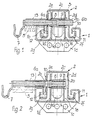
- Figur 1 -
- einen Querschnitt durch die Längsverstellvorrichtung im verriegelten Zustand,
- Figur 2 -
- den Querschnitt gemäß
Figur 1 im entriegelten Zustand.
- Figure 1 -
- 3 shows a cross section through the longitudinal adjustment device in the locked state,
- Figure 2 -
- the cross section of Figure 1 in the unlocked state.
Eine mit einem nicht dargestellten Kraftfahrzeugsitz verbundene,
im wesentlichen U-förmige Oberschiene 2 läuft auf
mehreren chassisfest gelagerten Laufrollen 3 ab. Die Oberschiene
2 wird in einer etwa C-förmigen Unterschiene geführt.
Auf den nach unten gekröpften Schenkeln 1a und 1b
der Unterschiene 1 sitzen Gleitkörper 11 und 12. Die beiden
Gleitkörper 11 und 12 greifen in die Rinnen 2f und 2g der
Oberschiene ein. Die Unterschiene 1 ist über Befestigungsflansche
1c am Fahrzeugboden befestigt. An die nach oben
weisende Innenseite des horizontalen Basisschenkels der Unterschiene
1 sind zueinander parallel und in Fahrzeuglängsrichtung
verlaufende senkrechte Flansch 1e und 1d angeschweißt.
Zwischen den beiden Flanschen 1e und 1d befindet
sich ein quer verlaufendes Distanzblech 4 mit einer Aussparung
4a.A connected to a motor vehicle seat, not shown,
essentially U-shaped
An der Unterschiene 1 ist seitlich eine quer zur Längsrichtung
verlaufene Hülse 13 angeschweißt, in der ein erster
Verriegelungsbolzen 6a quer verschieblich gelagert ist. Der
erste Verriegelungsbolzen 6a durchgreift in Verriegelungsstellung
eine Durchgangsöffnung 2a im Seitenschenkel 2e der
Oberschiene 2. Die Durchgangsöffnung 2a ist im dargestellten
Ausführungsbeispiel in einer Verstärkungsschiene 10 aus
Metall vorgesehen.On the
Mit der Hülse 13 fluchtet eine Hülse 8, die zwischen den
vertikal sich erstreckenden Flanschen 1e und 1d befestigt
ist. In der Hülse 8 ist ein zweiter Verriegelungsbolzen 6b
fluchtend mit dem ersten Verriegelungsbolzen 6a quer verschieblich
gelagert. Der zweite Verriegelungsbolzen 6b
greift im verriegelten Zustand gemäß Figur 1 mit seiner
Frontseite durch eine Durchgangsöffnung 2b im Seitenschenkel
2d der Oberschiene 2.With the
Der zweite Verriegelungsbolzen 6b steht unter der Wirkung
einer als Druckfeder ausgebildeten Rückstellfeder 9. Diese
Rückstellfeder 9 stützt sich einerseits an einem inneren
Kragen der Hülse 8 ab und andererseits an einem umlaufenden
Bund des zweiten Verriegelungsbolzens 6b.The
Der erste Verriegelungsbolzen 6a steht unter der Wirkung
einer Zugfeder 5. Die Federkraft der Zugfeder 5 ist größer
als die Federkraft der als Druckfeder ausgebildeten Rückstellfeder
9. Dies hat zur Folge, daß der Verriegelungsbolzen
6a bei passend gegenüberliegenden Durchgangsöffnungen
2a und 2d den zweiten Verriegelungsbolzen 6b in die in Figur
1 dargestellte Verriegelungsposition drückt.The
Zum Entriegeln wird der erste Verriegelungsbolzen 6a über
eine Zughaken 7 unter Überwindung der Kraft der Zugfeder 5
gemäß Figur 2 nach links gezogen, bis das vordere Ende des
Verriegelungsbolzens 6a aus der Durchgangsöffnung 2a ausgetaucht
ist. Gleichzeitig wird der zweite Verriegelungsbolzen
6b unter der Wirkung der Druckfeder 9 bis zu einem linken
Anschlag verschoben, wobei das vordere und in den
Zeichnungen rechte Ende des zweiten Verriegelungsbolzens 6b
aus der Ausnehmung 2b ausgetaucht ist. In dieser entriegelten
Lage kann der Sitz in Längsrichtung verschoben werden.To unlock the
Die mehrfach vorgesehenen Laufrollen 3 laufen auf der Innenseite
des Basisschenkels 2c der im wesentlichen Uförmigen
Oberschiene 2 ab.The
Claims (3)
- Longitudinal adjusting device for motor vehicle seats having a top rail (2) fixed on the seat and guided in a bottom rail (1) fixed on the chassis, with the top rail having a U-shaped basic profile and provided along one side arm (2e) with full-length through openings (2a) spaced out uniformly over the length and designed to hold a locking bolt fixed on the chassis and guided displaceable across the longitudinal direction, wherein the locking bolt is movable into the locking position under spring tension and into the release position against spring tension, characterised in that second full-length through openings (2b) are provided along the second side arm (2d) and aligned with the through openings of the first side arm (2e), the second through openings are designed for the purpose of engaging a second locking bolt (6b) which is guided fixed on the chassis and displaceable across the longitudinal direction, wherein the second locking bolt (6b) is in alignment with the first locking bolt (6a) and this first locking bolt (6a) for the purpose of locking adjoins the back of the second locking bolt (6b) and by means of the spring pretension moves the second locking bolt (6b) into the second full-length through opening (2b) on overcoming the resetting force of its resetting spring (9) so that the second locking bolt (6b) passes out of its opposite through opening under the force of its resetting spring (9) as soon as the first locking bolt releases the second locking bolt (6b).
- Longitudinal adjusting device according to claim 1 characterised in that the first locking bolt (6a) is under the pretension of a tension spring (5).
- Longitudinal adjusting device according to claim 1 or 2 characterised in that the second locking bolt (6b) is guided in a sleeve (8) enclosing same and its resetting spring (9) adjoins on one side on the inside a collar of the sleeve (8) and on the other side a collar of the second locking bolt (6b).
Applications Claiming Priority (2)
| Application Number | Priority Date | Filing Date | Title |
|---|---|---|---|
| DE19617691A DE19617691C1 (en) | 1996-05-03 | 1996-05-03 | Locking position adjuster for motor vehicle seat |
| DE19617691 | 1996-05-03 |
Publications (3)
| Publication Number | Publication Date |
|---|---|
| EP0805065A2 EP0805065A2 (en) | 1997-11-05 |
| EP0805065A3 EP0805065A3 (en) | 1998-12-30 |
| EP0805065B1 true EP0805065B1 (en) | 2001-05-23 |
Family
ID=7793171
Family Applications (1)
| Application Number | Title | Priority Date | Filing Date |
|---|---|---|---|
| EP97104376A Expired - Lifetime EP0805065B1 (en) | 1996-05-03 | 1997-03-14 | Longitudinal guide for automotive vehicle seats |
Country Status (2)
| Country | Link |
|---|---|
| EP (1) | EP0805065B1 (en) |
| DE (2) | DE19617691C1 (en) |
Families Citing this family (9)
| Publication number | Priority date | Publication date | Assignee | Title |
|---|---|---|---|---|
| DE29700866U1 (en) * | 1997-01-20 | 1997-03-20 | Burger Soehne | Locking device for a vehicle seat |
| DE19957201A1 (en) * | 1999-11-27 | 2001-06-07 | Giok Djien Go | Longitudinal adjustment mechanism with tools to minimize seat components, assembly time, manufacturing costs and stress |
| JP4542254B2 (en) * | 2000-11-21 | 2010-09-08 | アイシン精機株式会社 | Vehicle seat slide device |
| DE10152208A1 (en) * | 2001-10-23 | 2003-05-08 | Keiper Gmbh & Co | Seat locking device has at least one damping element for movement of locking element relative to first component |
| DE20313952U1 (en) * | 2003-09-05 | 2005-01-05 | Brose Fahrzeugteile Gmbh & Co. Kg, Coburg | Locking device for longitudinal vehicle seat adjuster has springs that bias locking pins towards openings in hollow volume formed by seat/latching rails, supported on locking pin supporting regions |
| DE102007042595B4 (en) * | 2007-09-07 | 2015-06-25 | Johnson Controls Gmbh | Adjusting device for longitudinal adjustment of a motor vehicle component |
| DE102010049542B4 (en) * | 2010-10-21 | 2019-02-14 | Adient Luxembourg Holding S.À R.L. | Longitudinal adjuster for a vehicle seat |
| JP6264075B2 (en) * | 2013-07-30 | 2018-01-24 | アイシン精機株式会社 | Vehicle seat slide device |
| DE102020207924B3 (en) | 2020-06-25 | 2021-07-29 | Brose Fahrzeugteile SE & Co. Kommanditgesellschaft, Coburg | Locking device for a vehicle seat with a locking element positively securing a locking element in a locking position, locking assembly and vehicle seat with such a locking device |
Family Cites Families (4)
| Publication number | Priority date | Publication date | Assignee | Title |
|---|---|---|---|---|
| FR2213662A5 (en) * | 1972-12-27 | 1974-08-02 | Nissan Motor | |
| JPS57194121A (en) * | 1981-05-22 | 1982-11-29 | Oi Seisakusho Co Ltd | Seat slide of automobile |
| JPH0431184Y2 (en) * | 1985-05-17 | 1992-07-27 | ||
| US5447352A (en) * | 1992-06-22 | 1995-09-05 | Aisin Seiki Kabushiki Kaisha | Seat slide mechanism for vehicles |
-
1996
- 1996-05-03 DE DE19617691A patent/DE19617691C1/en not_active Expired - Fee Related
-
1997
- 1997-03-14 EP EP97104376A patent/EP0805065B1/en not_active Expired - Lifetime
- 1997-03-14 DE DE59703579T patent/DE59703579D1/en not_active Expired - Lifetime
Also Published As
| Publication number | Publication date |
|---|---|
| DE59703579D1 (en) | 2001-06-28 |
| EP0805065A3 (en) | 1998-12-30 |
| EP0805065A2 (en) | 1997-11-05 |
| DE19617691C1 (en) | 1997-05-07 |
Similar Documents
| Publication | Publication Date | Title |
|---|---|---|
| DE4201354C2 (en) | Rail arrangement for a vehicle seat | |
| DE4314538C2 (en) | Rollover protection device for a motor vehicle | |
| EP2608988B1 (en) | Latching device for a head restraint | |
| WO1999008892A1 (en) | Locking device for vehicle seats, in particular motor vehicle seats | |
| EP3484742B1 (en) | Longitudinal adjuster and vehicle seat | |
| EP0805065B1 (en) | Longitudinal guide for automotive vehicle seats | |
| DE2522074B2 (en) | Locking device for the sliding guide of a longitudinally displaceable motor vehicle seat | |
| DE19626025B4 (en) | Seat slide mechanism | |
| DE19717667C5 (en) | Longitudinal guide for vehicle seat with two elongated rails and guide means | |
| EP0582934B1 (en) | Adjusting device for brakes, particularly for vehicle brakes | |
| EP0100049A2 (en) | Longitudinal glide with a seat-anchored safety belt for vehicle seats | |
| EP0729867A1 (en) | Rollover protection device | |
| EP0300470A1 (en) | Device for fastening a safety belt lock support to a recipient affixed to a vehicle | |
| EP0623492B1 (en) | Safety arch device for an automotive vehicle | |
| DE10056480A1 (en) | Seat adjuster for motor vehicle has rail fixed to floor with second rail attached to seat and locked by sprung claw | |
| DE102013002948A1 (en) | Belt buckle bringer for seat belt of vehicle, has carrier retained by acting seat harness release part tensile force on carrier, guide device operatively connected with blocking element of blocking device that is connected to guide rail | |
| EP4308411A1 (en) | Adjustment device for longitudinal adjustment of a vehicle seat, and additional locking for same | |
| DE3442159A1 (en) | Longitudinally adjustable seat, in particular motor vehicle seat, which can be fixed in selectable longitudinal positions | |
| DE3209351C2 (en) | ||
| DE102021214144A1 (en) | seat adjustment device | |
| EP0900689A1 (en) | Support for a vehicle seat, particularly a longitudinaly adjustable rear seat bench | |
| DE3706367C2 (en) | ||
| DE3306434C2 (en) | ||
| WO2004091962A1 (en) | Longitudinal guiding element for a motor vehicle seat | |
| DE102011120531A1 (en) | Movement device of seat attachment of seat assembly of motor vehicle, has fixing unit which is formed integrally and is not extended laterally over movement device |
Legal Events
| Date | Code | Title | Description |
|---|---|---|---|
| PUAI | Public reference made under article 153(3) epc to a published international application that has entered the european phase |
Free format text: ORIGINAL CODE: 0009012 |
|
| AK | Designated contracting states |
Kind code of ref document: A2 Designated state(s): DE FR GB IT |
|
| PUAL | Search report despatched |
Free format text: ORIGINAL CODE: 0009013 |
|
| AK | Designated contracting states |
Kind code of ref document: A3 Designated state(s): DE FR GB IT |
|
| 17P | Request for examination filed |
Effective date: 19981118 |
|
| GRAG | Despatch of communication of intention to grant |
Free format text: ORIGINAL CODE: EPIDOS AGRA |
|
| 17Q | First examination report despatched |
Effective date: 20000920 |
|
| GRAG | Despatch of communication of intention to grant |
Free format text: ORIGINAL CODE: EPIDOS AGRA |
|
| GRAH | Despatch of communication of intention to grant a patent |
Free format text: ORIGINAL CODE: EPIDOS IGRA |
|
| GRAH | Despatch of communication of intention to grant a patent |
Free format text: ORIGINAL CODE: EPIDOS IGRA |
|
| ITF | It: translation for a ep patent filed |
Owner name: SOCIETA' ITALIANA BREVETTI S.P.A. |
|
| RAP1 | Party data changed (applicant data changed or rights of an application transferred) |
Owner name: PROGRESS-WERK OBERKIRCH AKTIENGESELLSCHAFT Owner name: FAURECIA AUTOSITZE GMBH & CO. KG |
|
| GRAA | (expected) grant |
Free format text: ORIGINAL CODE: 0009210 |
|
| AK | Designated contracting states |
Kind code of ref document: B1 Designated state(s): DE FR GB IT |
|
| GBT | Gb: translation of ep patent filed (gb section 77(6)(a)/1977) |
Effective date: 20010523 |
|
| REF | Corresponds to: |
Ref document number: 59703579 Country of ref document: DE Date of ref document: 20010628 |
|
| ET | Fr: translation filed | ||
| REG | Reference to a national code |
Ref country code: GB Ref legal event code: IF02 |
|
| PLBE | No opposition filed within time limit |
Free format text: ORIGINAL CODE: 0009261 |
|
| STAA | Information on the status of an ep patent application or granted ep patent |
Free format text: STATUS: NO OPPOSITION FILED WITHIN TIME LIMIT |
|
| 26N | No opposition filed | ||
| PGFP | Annual fee paid to national office [announced via postgrant information from national office to epo] |
Ref country code: GB Payment date: 20090311 Year of fee payment: 13 |
|
| PGFP | Annual fee paid to national office [announced via postgrant information from national office to epo] |
Ref country code: IT Payment date: 20090327 Year of fee payment: 13 |
|
| PGFP | Annual fee paid to national office [announced via postgrant information from national office to epo] |
Ref country code: FR Payment date: 20090313 Year of fee payment: 13 |
|
| PGFP | Annual fee paid to national office [announced via postgrant information from national office to epo] |
Ref country code: DE Payment date: 20100223 Year of fee payment: 14 |
|
| GBPC | Gb: european patent ceased through non-payment of renewal fee |
Effective date: 20100314 |
|
| REG | Reference to a national code |
Ref country code: FR Ref legal event code: ST Effective date: 20101130 |
|
| PG25 | Lapsed in a contracting state [announced via postgrant information from national office to epo] |
Ref country code: FR Free format text: LAPSE BECAUSE OF NON-PAYMENT OF DUE FEES Effective date: 20100331 |
|
| PG25 | Lapsed in a contracting state [announced via postgrant information from national office to epo] |
Ref country code: GB Free format text: LAPSE BECAUSE OF NON-PAYMENT OF DUE FEES Effective date: 20100314 Ref country code: IT Free format text: LAPSE BECAUSE OF NON-PAYMENT OF DUE FEES Effective date: 20100314 |
|
| PG25 | Lapsed in a contracting state [announced via postgrant information from national office to epo] |
Ref country code: DE Free format text: LAPSE BECAUSE OF NON-PAYMENT OF DUE FEES Effective date: 20111001 |
|
| REG | Reference to a national code |
Ref country code: DE Ref legal event code: R119 Ref document number: 59703579 Country of ref document: DE Effective date: 20111001 |