EP0900689A1 - Support for a vehicle seat, particularly a longitudinaly adjustable rear seat bench - Google Patents
Support for a vehicle seat, particularly a longitudinaly adjustable rear seat bench Download PDFInfo
- Publication number
- EP0900689A1 EP0900689A1 EP98115871A EP98115871A EP0900689A1 EP 0900689 A1 EP0900689 A1 EP 0900689A1 EP 98115871 A EP98115871 A EP 98115871A EP 98115871 A EP98115871 A EP 98115871A EP 0900689 A1 EP0900689 A1 EP 0900689A1
- Authority
- EP
- European Patent Office
- Prior art keywords
- seat
- support
- vehicle
- seat frame
- guide rails
- Prior art date
- Legal status (The legal status is an assumption and is not a legal conclusion. Google has not performed a legal analysis and makes no representation as to the accuracy of the status listed.)
- Granted
Links
Images
Classifications
-
- B—PERFORMING OPERATIONS; TRANSPORTING
- B60—VEHICLES IN GENERAL
- B60N—SEATS SPECIALLY ADAPTED FOR VEHICLES; VEHICLE PASSENGER ACCOMMODATION NOT OTHERWISE PROVIDED FOR
- B60N2/00—Seats specially adapted for vehicles; Arrangement or mounting of seats in vehicles
- B60N2/24—Seats specially adapted for vehicles; Arrangement or mounting of seats in vehicles for particular purposes or particular vehicles
- B60N2/42—Seats specially adapted for vehicles; Arrangement or mounting of seats in vehicles for particular purposes or particular vehicles the seat constructed to protect the occupant from the effect of abnormal g-forces, e.g. crash or safety seats
- B60N2/43—Safety locks
-
- B—PERFORMING OPERATIONS; TRANSPORTING
- B60—VEHICLES IN GENERAL
- B60N—SEATS SPECIALLY ADAPTED FOR VEHICLES; VEHICLE PASSENGER ACCOMMODATION NOT OTHERWISE PROVIDED FOR
- B60N2/00—Seats specially adapted for vehicles; Arrangement or mounting of seats in vehicles
- B60N2/02—Seats specially adapted for vehicles; Arrangement or mounting of seats in vehicles the seat or part thereof being movable, e.g. adjustable
- B60N2/04—Seats specially adapted for vehicles; Arrangement or mounting of seats in vehicles the seat or part thereof being movable, e.g. adjustable the whole seat being movable
- B60N2/06—Seats specially adapted for vehicles; Arrangement or mounting of seats in vehicles the seat or part thereof being movable, e.g. adjustable the whole seat being movable slidable
- B60N2/065—Rear seats
-
- B—PERFORMING OPERATIONS; TRANSPORTING
- B60—VEHICLES IN GENERAL
- B60N—SEATS SPECIALLY ADAPTED FOR VEHICLES; VEHICLE PASSENGER ACCOMMODATION NOT OTHERWISE PROVIDED FOR
- B60N2/00—Seats specially adapted for vehicles; Arrangement or mounting of seats in vehicles
- B60N2/02—Seats specially adapted for vehicles; Arrangement or mounting of seats in vehicles the seat or part thereof being movable, e.g. adjustable
- B60N2/04—Seats specially adapted for vehicles; Arrangement or mounting of seats in vehicles the seat or part thereof being movable, e.g. adjustable the whole seat being movable
- B60N2/06—Seats specially adapted for vehicles; Arrangement or mounting of seats in vehicles the seat or part thereof being movable, e.g. adjustable the whole seat being movable slidable
- B60N2/07—Slide construction
- B60N2/0702—Slide construction characterised by its cross-section
- B60N2/071—T-shaped
-
- B—PERFORMING OPERATIONS; TRANSPORTING
- B60—VEHICLES IN GENERAL
- B60N—SEATS SPECIALLY ADAPTED FOR VEHICLES; VEHICLE PASSENGER ACCOMMODATION NOT OTHERWISE PROVIDED FOR
- B60N2/00—Seats specially adapted for vehicles; Arrangement or mounting of seats in vehicles
- B60N2/24—Seats specially adapted for vehicles; Arrangement or mounting of seats in vehicles for particular purposes or particular vehicles
- B60N2/42—Seats specially adapted for vehicles; Arrangement or mounting of seats in vehicles for particular purposes or particular vehicles the seat constructed to protect the occupant from the effect of abnormal g-forces, e.g. crash or safety seats
- B60N2/4207—Seats specially adapted for vehicles; Arrangement or mounting of seats in vehicles for particular purposes or particular vehicles the seat constructed to protect the occupant from the effect of abnormal g-forces, e.g. crash or safety seats characterised by the direction of the g-forces
- B60N2/4214—Seats specially adapted for vehicles; Arrangement or mounting of seats in vehicles for particular purposes or particular vehicles the seat constructed to protect the occupant from the effect of abnormal g-forces, e.g. crash or safety seats characterised by the direction of the g-forces longitudinal
- B60N2/4221—Seats specially adapted for vehicles; Arrangement or mounting of seats in vehicles for particular purposes or particular vehicles the seat constructed to protect the occupant from the effect of abnormal g-forces, e.g. crash or safety seats characterised by the direction of the g-forces longitudinal due to impact coming from the front
-
- B—PERFORMING OPERATIONS; TRANSPORTING
- B60—VEHICLES IN GENERAL
- B60N—SEATS SPECIALLY ADAPTED FOR VEHICLES; VEHICLE PASSENGER ACCOMMODATION NOT OTHERWISE PROVIDED FOR
- B60N2/00—Seats specially adapted for vehicles; Arrangement or mounting of seats in vehicles
- B60N2/24—Seats specially adapted for vehicles; Arrangement or mounting of seats in vehicles for particular purposes or particular vehicles
- B60N2/42—Seats specially adapted for vehicles; Arrangement or mounting of seats in vehicles for particular purposes or particular vehicles the seat constructed to protect the occupant from the effect of abnormal g-forces, e.g. crash or safety seats
- B60N2/427—Seats or parts thereof displaced during a crash
- B60N2/42772—Seats or parts thereof displaced during a crash characterised by the triggering system
- B60N2/42781—Seats or parts thereof displaced during a crash characterised by the triggering system mechanical triggering
Definitions
- the invention relates to a support for a vehicle seat according to the preamble of claim 1.
- Such support is, for example, with DE-U 90 12 256 described.
- supports of this type one can Vehicle seat and a seat can be easily moved be held on the seat rails.
- a Rear impact can be a bench with known Bend the support towards the vehicle floor and stay there deform.
- the object of the invention is to support the input to create the type with which a seat or a bench on two guide rails in the usual way can be easily moved, which, however, a Deform or pull up in a frontal crash or a downward deformation in a rear impact safely avoids.
- the seat guide rails can be installed in the vehicle within the usual tolerances become.
- the support rail attached to the vehicle floor affects mobility during normal use not of the seat, since the one with the seat frame connected securing part does not touch the support rail. Only when there are high extraordinary loads on the Seat deformations occur on the seat frame, such as that in the event of a crash, it will Engage the securing part on the support rail and one reliably prevent inadmissible deformation of the seat frame.
- the seat frame can thus be used for driving usual loads can be dimensioned without doing so the exceptionally higher loads in a crash are to be considered. This makes the seat opposite another without the support rail according to the invention easier to perform without reducing security is.
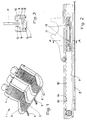
- a vehicle seat 1 comprises a seat frame 2, a seat surface 3 and backrest parts 4.
- On the seat frame 2 are on both sides each seat guide parts attached in itself in a known manner firmly connected to the vehicle floor 5
- Seat guide rails 6 slidably mounted as well can be locked by an actuator.
- On the vehicle floor 5 is between the two seat guide rails 6 and parallel to this a support rail 7 fixed.
- the support rail 7 has on one of them Seat frame 2 towards the side, a support track 8 on.
- the Teeth of the locking teeth 10 each have one to the rear of the vehicle facing steep flank 14 and one to the vehicle bow facing bevel 15.
- seat 1 Under normal load, seat 1 can sit on the seat guide rails 6 in the vehicle longitudinal direction according to Passenger requirements are postponed.
- the securing part 11 moves along the support rail 7 without touching it.
- a frontal crash of the Vehicle becomes the seat 1 due to the delay of its Mass with considerably greater force than in normal use pushed up, with a deformation of the Seat frame 2 in the form of a deflection between the both seat guide rails 6 enters upwards.
- Locking means 13 in engagement with the locking teeth 10 the support rail 7.
- the fixed to the vehicle floor 5 Support rail 7 prevents both another Deform the seat frame 2 upwards as well unwanted displacement of the seat 1 within the vehicle forward.
- seat 1 In the event of a rear-end collision, as seen in e.g. B. by a Rear-end collision results, seat 1 is above normal Load dimension pressed towards the vehicle floor 5. This causes the seat frame 2 to bend downwards by. The securing part 11 connected to it arrives thereby with its support surface 12 on the support track 8 the support rail 7 and thus prevents an impermissible Deformation of the seat 1.
- the particular advantage of the invention is that that the seat frame 2 of a seat in its strength only needs to be designed for normal loads and so compared to an interpretation for extreme loads in the event of a crash, much easier and therefore more user-friendly can be. Nevertheless, this resists the extreme stress caused by a crash then additional support from the support rail 7 and the securing part 11. Moving the Seat under normal conditions is supported by the support rail 7 and the securing part 11 is not hindered. Especially with one that spans the entire width of the vehicle Seat can be arranged by arranging one or more the stability behavior distributed over the width of the support rails 7 can be improved without the weight of the Seat is enlarged.
Abstract
Description
Die Erfindung betrifft eine Abstützung eines Fahrzeugsitzes
gemäß dem Oberbegriff des Patentanspruches 1.The invention relates to a support for a vehicle seat
according to the preamble of
Eine solche Abstützung ist beispielsweise mit DE-U 90 12 256 beschrieben. Mit Abstutzungen dieser Art kann ein Fahrzeugsitz und auch eine Sitzbank leicht verschiebbar auf den Sitzschienen gehalten werden. Insbesondere bei dem gegenüber Einzelsitzen größeren Gewicht von Sitzbänken besteht jedoch die Gefahr, daR bei einem Frontcrash des Fahrzeugs die Sitzbank nach oben verformt wird oder gar aus der Führung der Sitzschienen herausreißt. Bei einem Heckaufprall kann sich eine Sitzbank mit bekannter Abstützung zum Fahrzeugboden hin durchbiegen und bleibend deformieren.Such support is, for example, with DE-U 90 12 256 described. With supports of this type, one can Vehicle seat and a seat can be easily moved be held on the seat rails. Especially at the greater weight of bench seats compared to individual seats however, there is a risk of a front crash of the vehicle the seat is deformed upwards or even tears out of the guide of the seat rails. At a Rear impact can be a bench with known Bend the support towards the vehicle floor and stay there deform.
Die Anordnung einer zusätzliche Sitzschiene in der Mitte einer Sitzbank erfordert erheblichen Aufwand, da sie genau parallel zu den seitlichen Sitzschienen angeordnet sein muß und sich zu diesen im Betrieb nicht verziehen darf. Dies ist praktisch bei der relativen Nachgiebigkeit des Fahrzeugbodens im Vergleich zu den Seitenschwellern kaum möglich. Außerdem wird durch eine Lagerung des Sitzes in drei Führungsschienen auch bei exakter Schienenausrichtung die Betätigungskraft zum Verschieben des Sitzes unzumutbar groß. The arrangement of an additional seat rail in the middle A bench seat requires considerable effort since it is accurate arranged parallel to the side seat rails must be and do not warp to these in the company may. This comes in handy with relative compliance of the vehicle floor compared to the side skirts hardly possible. In addition, by storing the seat in three guide rails even with exact rail alignment the actuating force for moving the seat unreasonably large.
Aufgabe der Erfindung ist es, eine Abstützung der eingangs genannten Art zu schaffen, mit der ein Sitz oder eine Sitzbank auf zwei Führungsschienen in üblicher Weise leicht verschiebbar gelagert` werden kann, die jedoch ein Verformen oder Ausreißen nach oben bei einem Frontalcrash oder eine Deformation nach unten bei einem Heckaufprall sicher vermeidet.The object of the invention is to support the input to create the type with which a seat or a bench on two guide rails in the usual way can be easily moved, which, however, a Deform or pull up in a frontal crash or a downward deformation in a rear impact safely avoids.
Diese Aufgabe wird erfindungsgemäß mit den kennzeichnenden
Merkmalen des Anspruches 1 gelöst.This object is achieved with the characteristic
Features of
Vorteilhafte Weiterbildungen der Erfindung sind Gegenstand der Unteransprüche.Advantageous developments of the invention are the subject of subclaims.
Durch die Lagerung des Sitzes auf zwei üblichen Sitzführungsschienen kann bei normaler Belastung der Sitz in üblicher Weise leicht verschoben werden. Die Sitzführungsschienen können in üblichen Toleranzen im Fahrzeug eingebaut werden. Die am Fahrzeugboden befestigte Stützschiene beeinträchtigt bei üblicher Benutzung die Bewegungsfähigkeit des Sitzes nicht, da dabei der mit dem Sitzgestell verbundene Sicherungsteil die Stützschiene nicht berührt. Erst wenn durch hohe außergewöhnliche Belastungen auf den Sitz Verformungen am Sitzgestell auftreten, wie das beispielsweise bei einem Crash der Fall ist, dann wird das Sicherungsteil an der Stützschiene eingreifen und eine unzulässige Verformung des Sitzgestells zuverlässig verhindern. Das Sitzgestell kann so für die im Fahrbetrieb üblichen Belastungen dimensioniert werden, ohne daß dabei die außergewöhnlich höheren Belastungen bei einem Crash zu berücksichtigen sind. Dadurch ist der Sitz gegenüber einem anderen ohne die erfindungsgemäße Stützschiene leichter ausführbar, ohne daß die Sicherheit reduziert ist.By storing the seat on two common seat guide rails can with normal load the seat in the usual Way easily moved. The seat guide rails can be installed in the vehicle within the usual tolerances become. The support rail attached to the vehicle floor affects mobility during normal use not of the seat, since the one with the seat frame connected securing part does not touch the support rail. Only when there are high extraordinary loads on the Seat deformations occur on the seat frame, such as that in the event of a crash, it will Engage the securing part on the support rail and one reliably prevent inadmissible deformation of the seat frame. The seat frame can thus be used for driving usual loads can be dimensioned without doing so the exceptionally higher loads in a crash are to be considered. This makes the seat opposite another without the support rail according to the invention easier to perform without reducing security is.
Im allgemeinen wird eine mittig, zwischen den Sitzführungsschienen befindliche Stützschiene ausreichen, um einen Sitz vor unzulässigen Verformungen zu schützen. Es ist jedoch durchaus möglich und entspricht auch der Erfindung, wenn über die Breite einer Sitzbank verteilt mehrere Sitzschienen vorgesehen werden.Generally, one becomes centered between the seat guide rails located support rail are sufficient to one To protect the seat against impermissible deformations. It is entirely possible and also corresponds to the invention, if spread over the width of a bench several seat rails can be provided.
Ein Ausführungsbeispiel der Erfindung ist nachstehend anhand einer Zeichnung näher beschrieben. Es zeigen
- Fig. 1:
- eine gemäß der Erfindung abgestützte Sitzbank;
- Fig. 2:
- eine Seitenansicht der Stützschiene;
- Fig. 3:
- einen Schnitt entlang der Linie A - A in
Figur 2.
- Fig. 1:
- a bench supported according to the invention;
- Fig. 2:
- a side view of the support rail;
- Fig. 3:
- a section along the line A - A in Figure 2.
Ein Fahrzeugsitz 1 umfaßt ein Sitzgestell 2, eine Sitzfläche
3 und Lehnenteile 4. Am Sitzgestell 2 sind beidseits
jeweils Sitzführungsteile befestigt, die in an sich
bekannter Weise in mit dem Fahrzeugboden 5 fest verbundenen
Sitzführungsschienen 6 verschiebbar gelagert sowie
durch eine Betätigungseinrichtung arretierbar sind. Auf
dem Fahrzeugboden 5 ist zwischen den beiden Sitzführungsschienen
6 und parallel zu diesen eine Stützschiene 7
festgelegt. Die Stützschiene 7 weist an einer ihrer zum
Sitzgestell 2 hin gerichteten Seite eine Abstützbahn 8
auf. An zwei von der Abstützbahn 8 abgewinkelten Stegen 9
befindet sich jeweils eine Rastverzahnung 10, deren Zähne
von dem Sitzgestell 2 weggerichtet sind. Zwischen den
Stegen 9 und somit zwischen der Rastverzahnung 10 befindet
sich ein mit dem Sitzgestell 2 fest verbundenes Sicherungsteil
11, welches im Bereich der Abstützbahn 8
eine Abstützfläche 12 und im Bereich der Rastverzahnung
10 Rastmittel 13 hat. Zwischen der Abstützfläche 12 und
der Abstützbahn 8 sowie zwischen den Rastmitteln 13 und
der Rastverzahnung 10 ist ein Abstand, der so bemessen
ist, daß sich bei Normalbelastung des Sitzes 1 die Stützschiene
7 und das Sicherungsteil 11 nicht berühren. Die
Zähne der Rastverzahnung 10 haben jeweils eine zur Fahrzeugrückseite
weisende Steilflanke 14 und eine zum Fahrzeugbug
weisende Schrägflanke 15.A
Unter normaler Belastung kann der Sitz 1 auf den Sitzführungsschienen
6 in Fahrzeuglängsrichtung entsprechend den
Erfordernissen der Passagiere verschoben werden. Dabei
bewegt sich das Sicherungsteil 11 entlang der Stützschiene
7, ohne diese zu berühren. Bei einem Frontalcrash des
Fahrzeuges wird der Sitz 1 infolge der Verzögerung seiner
Masse mit erheblich größerer Kraft als bei Normalbenutzung
nach oben gedrückt, wobei auch eine Verformung des
Sitzgestells 2 in Form einer Durchbiegung zwischen den
beiden Sitzführungsschienen 6 nach oben eintritt. Dabei
gelangen die fest mit dem Sicherungsteil 11 verbundenen
Rastmittel 13 in Eingriff mit der Rastverzahnung 10 an
der Stützschiene 7. Die fest mit dem Fahrzeugboden 5 verbundene
Stützschiene 7 verhindert dabei sowohl ein weiteres
Verformen des Sitzgestells 2 nach oben als auch ein
ungewolltes Verschieben des Sitzes 1 innerhalb des Fahrzeuges
nach vorn. Die Steilflanken 14 der Verzahnung halten
die Rastmittel 13, die im Ausführungsbeispiel als
Bolzen ausgeführt sind, an ihrem Ort fest. Durch die Anordnung
von Steilflanken 14 und Schrägflanken 15 kann ein
sicherer Eingriff sowie ein guter Halteeffekt der Rastmittel
13 erzielt werden.Under normal load,
Bei einem Heckaufprall, wie er sich z. B. durch einen
Auffahrunfall ergibt, wird der Sitz 1 über das normale
Belastungsmaß hinaus in Richtung Fahrzeugboden 5 gedrückt.
Dadurch biegt sich das Sitzgestell 2 nach unten
durch. Das mit ihm verbundene Sicherungsteil 11 gelangt
dabei mit seiner Abstützfläche 12 auf die Abstützbahn 8
der Stützschiene 7 und verhindert so eine unzulässige
Verformung des Sitzes 1. In the event of a rear-end collision, as seen in e.g. B. by a
Rear-end collision results,
Der besondere Vorteil der Erfindung ist darin zu sehen,
daß das Sitzgestell 2 eines Sitzes in seiner Festigkeit
lediglich auf die Normalbelastung ausgelegt werden muß
und so gegenüber einer Auslegung auf Extrembelastungen
bei einem Crash sehr viel leichter und damit auch bedienungsfreundlicher
sein kann. Trotzdem widersteht dieser
leichte Sitz den Extrembelastungen eines Crashs durch die
dann zusätzlich eintretende Abstützung durch die Stützschiene
7 und das Sicherungsteil 11. Das Verschieben des
Sitzes unter Normalbedingungen wird durch die Stützschiene
7 und das Sicherungsteil 11 nicht behindert. Besonders
bei einer über die gesamte Fahrzeugbreite reichenden
Sitzbank kann durch Anordnung einer oder auch mehrerer
über die Breite verteilter Stützschienen 7 das Stabilitätsverhalten
verbessert werden, ohne daß das Gewicht der
Sitzbank vergrößert wird.The particular advantage of the invention is that
that the
Claims (4)
Applications Claiming Priority (2)
| Application Number | Priority Date | Filing Date | Title |
|---|---|---|---|
| DE19739038 | 1997-09-05 | ||
| DE19739038A DE19739038A1 (en) | 1997-09-05 | 1997-09-05 | Support of a vehicle seat, in particular a longitudinally adjustable rear seat |
Publications (2)
| Publication Number | Publication Date |
|---|---|
| EP0900689A1 true EP0900689A1 (en) | 1999-03-10 |
| EP0900689B1 EP0900689B1 (en) | 2001-12-05 |
Family
ID=7841421
Family Applications (1)
| Application Number | Title | Priority Date | Filing Date |
|---|---|---|---|
| EP98115871A Expired - Lifetime EP0900689B1 (en) | 1997-09-05 | 1998-08-22 | Support for a vehicle seat, particularly a longitudinaly adjustable rear seat bench |
Country Status (3)
| Country | Link |
|---|---|
| EP (1) | EP0900689B1 (en) |
| DE (2) | DE19739038A1 (en) |
| ES (1) | ES2169466T3 (en) |
Cited By (3)
| Publication number | Priority date | Publication date | Assignee | Title |
|---|---|---|---|---|
| WO2004012958A1 (en) * | 2002-07-31 | 2004-02-12 | Johnson Controls Gmbh | Safety device for vehicle seats |
| US7290822B2 (en) | 2005-08-26 | 2007-11-06 | Gm Global Technology Operations, Inc. | Occupant seat system |
| WO2019011667A1 (en) * | 2017-07-14 | 2019-01-17 | Adient Engineering and IP GmbH | Longitudinal adjuster for a vehicle seat, and vehicle seat |
Families Citing this family (4)
| Publication number | Priority date | Publication date | Assignee | Title |
|---|---|---|---|---|
| DE10219612B4 (en) * | 2002-05-02 | 2005-12-08 | Tillmann Profil Gmbh | Method for producing a rail with an internally arranged toothing and rail produced by this method |
| DE10311869B4 (en) * | 2003-03-17 | 2008-06-19 | C. Rob. Hammerstein Gmbh & Co. Kg | Multiple seat for motor vehicles |
| DE102011117361B4 (en) | 2011-10-29 | 2021-11-04 | Volkswagen Ag | Low-deformation body floor to support a seat rail |
| DE102015224098B4 (en) * | 2015-12-02 | 2020-11-19 | Volkswagen Aktiengesellschaft | Rail system and vehicle with such a rail system |
Citations (4)
| Publication number | Priority date | Publication date | Assignee | Title |
|---|---|---|---|---|
| DE9012256U1 (en) * | 1990-08-25 | 1990-11-29 | Schuler, Karl-Heinz, 7980 Ravensburg, De | |
| US5366268A (en) * | 1993-10-04 | 1994-11-22 | General Motors Corporation | High strength seat back |
| WO1996038318A1 (en) * | 1995-06-02 | 1996-12-05 | Aluminum Company Of America | Load bearing automotive bench seat assembly |
| EP0779176A1 (en) * | 1995-12-15 | 1997-06-18 | Scholte Management B.V. | Vehicle rear seat |
Family Cites Families (1)
| Publication number | Priority date | Publication date | Assignee | Title |
|---|---|---|---|---|
| DE19620877C1 (en) * | 1996-05-23 | 1997-06-26 | Bayerische Motoren Werke Ag | Motor-vehicle seating system |
-
1997
- 1997-09-05 DE DE19739038A patent/DE19739038A1/en not_active Withdrawn
-
1998
- 1998-08-22 ES ES98115871T patent/ES2169466T3/en not_active Expired - Lifetime
- 1998-08-22 DE DE59802306T patent/DE59802306D1/en not_active Expired - Lifetime
- 1998-08-22 EP EP98115871A patent/EP0900689B1/en not_active Expired - Lifetime
Patent Citations (4)
| Publication number | Priority date | Publication date | Assignee | Title |
|---|---|---|---|---|
| DE9012256U1 (en) * | 1990-08-25 | 1990-11-29 | Schuler, Karl-Heinz, 7980 Ravensburg, De | |
| US5366268A (en) * | 1993-10-04 | 1994-11-22 | General Motors Corporation | High strength seat back |
| WO1996038318A1 (en) * | 1995-06-02 | 1996-12-05 | Aluminum Company Of America | Load bearing automotive bench seat assembly |
| EP0779176A1 (en) * | 1995-12-15 | 1997-06-18 | Scholte Management B.V. | Vehicle rear seat |
Cited By (7)
| Publication number | Priority date | Publication date | Assignee | Title |
|---|---|---|---|---|
| WO2004012958A1 (en) * | 2002-07-31 | 2004-02-12 | Johnson Controls Gmbh | Safety device for vehicle seats |
| US7195311B2 (en) | 2002-07-31 | 2007-03-27 | Johnson Controls Gmbh | Safety device for vehicle seats |
| US7290822B2 (en) | 2005-08-26 | 2007-11-06 | Gm Global Technology Operations, Inc. | Occupant seat system |
| WO2019011667A1 (en) * | 2017-07-14 | 2019-01-17 | Adient Engineering and IP GmbH | Longitudinal adjuster for a vehicle seat, and vehicle seat |
| CN110914104A (en) * | 2017-07-14 | 2020-03-24 | 安道拓工程技术知识产权有限公司 | Longitudinal adjuster for a vehicle seat and vehicle seat |
| US11065986B2 (en) | 2017-07-14 | 2021-07-20 | Adient Engineering and IP GmbH | Longitudinal adjuster for a vehicle seat, and vehicle seat |
| CN110914104B (en) * | 2017-07-14 | 2022-08-02 | 恺博座椅机械部件有限公司 | Longitudinal adjuster for a vehicle seat and vehicle seat |
Also Published As
| Publication number | Publication date |
|---|---|
| DE59802306D1 (en) | 2002-01-17 |
| DE19739038A1 (en) | 1999-03-11 |
| ES2169466T3 (en) | 2002-07-01 |
| EP0900689B1 (en) | 2001-12-05 |
Similar Documents
| Publication | Publication Date | Title |
|---|---|---|
| DE102010051325B4 (en) | Seat base for a person seat | |
| DE4201354C2 (en) | Rail arrangement for a vehicle seat | |
| EP0608558B1 (en) | Passenger enclosure with a transverse reinforcement in the area of the seats | |
| DE10003853B4 (en) | Vehicle seat with a movable safety crossbar | |
| DE102016109789B4 (en) | Seating system for a cab of a means of transport with a row of seats that can be compacted | |
| EP0771690A2 (en) | Vehicle seat | |
| DE3023035A1 (en) | VEHICLE SEAT, IN PARTICULAR FOR MOTOR VEHICLES | |
| DE10051669C2 (en) | Device for guiding a seat of a vehicle | |
| DE102015215592B4 (en) | vehicle seat | |
| EP0492076B1 (en) | Double passenger seat | |
| DE10033340C1 (en) | Seat fixing device, for vehicle, has rail in which seat moves and at least one foot element connected between rail and vehicle floor and having deformation section to absorb energy in accident | |
| EP0900689B1 (en) | Support for a vehicle seat, particularly a longitudinaly adjustable rear seat bench | |
| DE102019209658A1 (en) | Device for a rail vehicle and rail vehicle | |
| DE10235086B4 (en) | Safety device for vehicle seats | |
| EP2481629A2 (en) | Vehicle seat with securing means for a support element | |
| DE2142609A1 (en) | Device for the mutual locking of two mutually displaceable components | |
| DE3531992C2 (en) | Adjustment device for a motor vehicle rear seat back that is adjustable in its inclination | |
| DE102017201356A1 (en) | Seat support for a vehicle seat | |
| DE102016008379A1 (en) | Lower guide frame of a vertical vibration system, sliding seat guide of a vehicle seat, vertical vibration system for a vehicle seat and vehicle seat | |
| DE19712902C1 (en) | Cockpit cross-member in motor vehicle | |
| EP0743220A2 (en) | Sliding rail guide for vehicle seats | |
| EP4308411A1 (en) | Adjustment device for longitudinal adjustment of a vehicle seat, and additional locking for same | |
| EP1615795B1 (en) | Longitudinal guiding element for a motor vehicle seat | |
| DE19926085A1 (en) | Mechanical absorption device especially for pilot's seat in aircraft has absorber plate supported on one component and suspension component supported on another, and suspension component has pin fitting in hole in absorber plate | |
| DE3301116A1 (en) | ADJUSTMENT FOR VEHICLE SEATS |
Legal Events
| Date | Code | Title | Description |
|---|---|---|---|
| PUAI | Public reference made under article 153(3) epc to a published international application that has entered the european phase |
Free format text: ORIGINAL CODE: 0009012 |
|
| AK | Designated contracting states |
Kind code of ref document: A1 Designated state(s): DE ES FR GB IT SE |
|
| AX | Request for extension of the european patent |
Free format text: AL;LT;LV;MK;RO;SI |
|
| 17P | Request for examination filed |
Effective date: 19990818 |
|
| AKX | Designation fees paid |
Free format text: DE ES FR GB IT SE |
|
| GRAG | Despatch of communication of intention to grant |
Free format text: ORIGINAL CODE: EPIDOS AGRA |
|
| GRAG | Despatch of communication of intention to grant |
Free format text: ORIGINAL CODE: EPIDOS AGRA |
|
| GRAH | Despatch of communication of intention to grant a patent |
Free format text: ORIGINAL CODE: EPIDOS IGRA |
|
| 17Q | First examination report despatched |
Effective date: 20010510 |
|
| GRAH | Despatch of communication of intention to grant a patent |
Free format text: ORIGINAL CODE: EPIDOS IGRA |
|
| GRAA | (expected) grant |
Free format text: ORIGINAL CODE: 0009210 |
|
| AK | Designated contracting states |
Kind code of ref document: B1 Designated state(s): DE ES FR GB IT SE |
|
| REG | Reference to a national code |
Ref country code: GB Ref legal event code: IF02 |
|
| REF | Corresponds to: |
Ref document number: 59802306 Country of ref document: DE Date of ref document: 20020117 |
|
| GBT | Gb: translation of ep patent filed (gb section 77(6)(a)/1977) |
Effective date: 20020201 |
|
| ET | Fr: translation filed | ||
| REG | Reference to a national code |
Ref country code: ES Ref legal event code: FG2A Ref document number: 2169466 Country of ref document: ES Kind code of ref document: T3 |
|
| PLBE | No opposition filed within time limit |
Free format text: ORIGINAL CODE: 0009261 |
|
| STAA | Information on the status of an ep patent application or granted ep patent |
Free format text: STATUS: NO OPPOSITION FILED WITHIN TIME LIMIT |
|
| 26N | No opposition filed | ||
| REG | Reference to a national code |
Ref country code: GB Ref legal event code: 732E Free format text: REGISTERED BETWEEN 20090219 AND 20090225 |
|
| REG | Reference to a national code |
Ref country code: GB Ref legal event code: 732E Free format text: REGISTERED BETWEEN 20090305 AND 20090311 |
|
| REG | Reference to a national code |
Ref country code: GB Ref legal event code: 732E Free format text: REGISTERED BETWEEN 20091029 AND 20091104 |
|
| REG | Reference to a national code |
Ref country code: GB Ref legal event code: 732E Free format text: REGISTERED BETWEEN 20091105 AND 20091111 |
|
| REG | Reference to a national code |
Ref country code: DE Ref legal event code: R081 Ref document number: 59802306 Country of ref document: DE Owner name: GM GLOBAL TECHNOLOGY OPERATIONS LLC (N. D. GES, US Free format text: FORMER OWNER: GM GLOBAL TECHNOLOGY OPERATIONS, INC., DETROIT, MICH., US Effective date: 20110323 Ref country code: DE Ref legal event code: R081 Ref document number: 59802306 Country of ref document: DE Owner name: GM GLOBAL TECHNOLOGY OPERATIONS LLC (N. D. GES, US Free format text: FORMER OWNER: GM GLOBAL TECHNOLOGY OPERATIONS, INC., DETROIT, US Effective date: 20110323 |
|
| PGFP | Annual fee paid to national office [announced via postgrant information from national office to epo] |
Ref country code: GB Payment date: 20120822 Year of fee payment: 15 Ref country code: SE Payment date: 20120813 Year of fee payment: 15 |
|
| PGFP | Annual fee paid to national office [announced via postgrant information from national office to epo] |
Ref country code: ES Payment date: 20120907 Year of fee payment: 15 Ref country code: DE Payment date: 20120816 Year of fee payment: 15 Ref country code: IT Payment date: 20120810 Year of fee payment: 15 Ref country code: FR Payment date: 20120823 Year of fee payment: 15 |
|
| REG | Reference to a national code |
Ref country code: SE Ref legal event code: EUG |
|
| GBPC | Gb: european patent ceased through non-payment of renewal fee |
Effective date: 20130822 |
|
| PG25 | Lapsed in a contracting state [announced via postgrant information from national office to epo] |
Ref country code: SE Free format text: LAPSE BECAUSE OF NON-PAYMENT OF DUE FEES Effective date: 20130823 Ref country code: DE Free format text: LAPSE BECAUSE OF NON-PAYMENT OF DUE FEES Effective date: 20140301 |
|
| REG | Reference to a national code |
Ref country code: DE Ref legal event code: R119 Ref document number: 59802306 Country of ref document: DE Effective date: 20140301 |
|
| REG | Reference to a national code |
Ref country code: FR Ref legal event code: ST Effective date: 20140430 |
|
| PG25 | Lapsed in a contracting state [announced via postgrant information from national office to epo] |
Ref country code: IT Free format text: LAPSE BECAUSE OF NON-PAYMENT OF DUE FEES Effective date: 20130822 |
|
| PG25 | Lapsed in a contracting state [announced via postgrant information from national office to epo] |
Ref country code: GB Free format text: LAPSE BECAUSE OF NON-PAYMENT OF DUE FEES Effective date: 20130822 |
|
| PG25 | Lapsed in a contracting state [announced via postgrant information from national office to epo] |
Ref country code: FR Free format text: LAPSE BECAUSE OF NON-PAYMENT OF DUE FEES Effective date: 20130902 |
|
| PG25 | Lapsed in a contracting state [announced via postgrant information from national office to epo] |
Ref country code: ES Free format text: LAPSE BECAUSE OF NON-PAYMENT OF DUE FEES Effective date: 20130823 |