EP0804999A2 - Pneumatisch anpassbares Einrichtungswerkzeug - Google Patents
Pneumatisch anpassbares Einrichtungswerkzeug Download PDFInfo
- Publication number
- EP0804999A2 EP0804999A2 EP97303024A EP97303024A EP0804999A2 EP 0804999 A2 EP0804999 A2 EP 0804999A2 EP 97303024 A EP97303024 A EP 97303024A EP 97303024 A EP97303024 A EP 97303024A EP 0804999 A2 EP0804999 A2 EP 0804999A2
- Authority
- EP
- European Patent Office
- Prior art keywords
- diaphragm
- housing
- cluster
- lens
- rods
- Prior art date
- Legal status (The legal status is an assumption and is not a legal conclusion. Google has not performed a legal analysis and makes no representation as to the accuracy of the status listed.)
- Granted
Links
Images

Classifications
-
- B—PERFORMING OPERATIONS; TRANSPORTING
- B24—GRINDING; POLISHING
- B24B—MACHINES, DEVICES, OR PROCESSES FOR GRINDING OR POLISHING; DRESSING OR CONDITIONING OF ABRADING SURFACES; FEEDING OF GRINDING, POLISHING, OR LAPPING AGENTS
- B24B13/00—Machines or devices designed for grinding or polishing optical surfaces on lenses or surfaces of similar shape on other work; Accessories therefor
- B24B13/02—Machines or devices designed for grinding or polishing optical surfaces on lenses or surfaces of similar shape on other work; Accessories therefor by means of tools with abrading surfaces corresponding in shape with the lenses to be made
-
- B—PERFORMING OPERATIONS; TRANSPORTING
- B24—GRINDING; POLISHING
- B24B—MACHINES, DEVICES, OR PROCESSES FOR GRINDING OR POLISHING; DRESSING OR CONDITIONING OF ABRADING SURFACES; FEEDING OF GRINDING, POLISHING, OR LAPPING AGENTS
- B24B13/00—Machines or devices designed for grinding or polishing optical surfaces on lenses or surfaces of similar shape on other work; Accessories therefor
- B24B13/01—Specific tools, e.g. bowl-like; Production, dressing or fastening of these tools
Definitions
- This invention relates generally to the manufacture of ophthalmic lenses and more particularly concerns conformal tools for fining and polishing ophthalmic lenses.
- finishing/polishing tools provide a global conformance to the lens, requiring a separate tool for every possible contour of lens. For each lens, the proper tool has to be selected and mounted on the fining/polishing apparatus. With recent development of more accurate lens surfacing equipment, modern lenses exhibit wide variations in face curvature.
- One presently known conformal tool applies air pressure under the control of the operator in the bladder of the conformal tool to control the degree of conformance to the lens.
- air pressure or hydraulic pressure in the tool bladder under operator control introduces considerable inaccuracy into the system.
- the face of the tool tends to buckle and lose its integrity with the lens surface, introducing further error into the system.
- conformal tools use a conformable filler in a pliant casing to contour the tool to the lens.
- Such tools eliminate the introduction of error due to the operators subjective introduction of air into the bladder.
- all the fluids or particles of the conformable filler are free to shift in any direction in response to the many forces exerted on the tool including the rotational motion of the tool and the axial displacement of the tool as well as the contour of the lens. Consequently, not all fluid or particle movement is directed toward achieving conformance.
- an object of this invention to provide a conformal tool for fining/polishing ophthalmic lenses affording unidirectional movement of the conformal medium toward the lens.
- Another object of this invention is to provide a conformal tool for fining/polishing ophthalmic lenses which restricts movement of the conformal medium in any direction other than toward the lens.
- Still another object of this invention is to provide a conformal tool for fining/polishing ophthalmic lenses which transforms multidirectional pneumatic pressure into unidirectional mechanical force to achieve conformance of a diaphragm to a lens.
- a further object of this invention is to provide a conformal tool for fining/polishing ophthalmic lenses which is capable of fining and polishing any lens within the range of plano to 14 diopters.
- Another object of this invention is to provide a conformal tool for fining/polishing ophthalmic lenses which is capable of fining and polishing any lens within a range of plano to 14 diopters with at least the added capability of 4 diopters of cylinder.
- Yet another object of this invention is to provide a conformal tool for fining/polishing ophthalmic lenses which is usable for both fining and polishing.
- a tool which has an outer shell or housing containing a bundle of rods of a plastic material, all of the rods being of equal length
- the clustered rods are individually free to move up and down unidirectionally along their vertical axes but are constrained against relative motion in any other direction.
- the rods are encased in an open ended tubular housing, the open ends being closed by two resiliently elastic diaphragms, one located at each end of the housing.
- An air chamber at one end of the housing receives compressed air and exerts pressure upon a first of the diaphragms.
- the first diaphragm in turn exerts pressure upon the abutting ends of the rods, forcing the opposite ends of the rods against the second diaphragm which in turn stretches to move with the rods.
- the second diaphragm, or a conformal pad applied to it contacts the surface of the lens during fining and polishing.
- the second diaphragm is stretched by the unidirectionally driven rods to provide a sponge-like pad which conforms to the surface of the lens.
- the diaphragm As the diaphragm is moved over the surface of the lens, it complies vertically with the change in the lens surface contour immediately and appears to "flow" over the lens surface.
- the clustered rods simultaneously resist changes that are made in a horizontal mode, thus presenting a hard surface to the lens and allowing the abrasives on the conformal pads applied to the second diaphragm to have a positive effect while being moved.
- the tubular housing is typically, but not necessarily, interiorly cylindrical.
- the rods are held in an hexagonal bundle by six identical isometric trapezoidal plates girded by a pair of O-rings seated in slots at the plate junctions.
- the O-rings are slightly compressed between the housing inner wall and the plates to secure the hexagonal assembly within the cylindrical housing
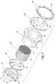
- the components of a preferred embodiment of the pneumatically assisted unidirectional conformal tool include a housing 10, containing a cluster of rods 30 between a top diaphragm 50 and a bottom diaphragm 60.
- the top diaphragm 50 is sandwiched against the housing 10 by a pneumatic cap 70 and the bottom diaphragm 60 is sandwiched against the housing 10 by a bottom ring 90.
- the housing 10 consists of a cylindrical wall 11 having an annular flange 13 about its lower end in a tophat-like configuration.
- An annular bevel 15 is provided along the inner periphery of the upper portion of the cylindrical wall 11.
- a plurality of tap holes 17 are provided into the top face of the cylindrical wall 11 outside of the bevel 15, the tap holes 17 extending longitudinally into the cylindrical wall 11 at intervals about its circumference. As shown, eight tap holes 17 are equally spaced in the top of the cylindrical wall 11.
- Another set of tap holes 19 are provided in the annular flange 13, the lower tap holes 19 extending longitudinally into the flange 13 at intervals circumferentially spaced about the flange 13. As shown, eight lower tap holes 19 are equally spaced apart in the flange 13.
- the outer beveled diameter 21 of the cylindrical wall 11 is greater than its inner wall diameter 23 and less than the diameter 25 along which the lower tap holes 17 are arranged.
- the thickness of the cylindrical wall 11 could be increased to be substantially equal to the outer diameter of the flange 13 so that the tap holes 13 and 17 can be longitudinally aligned and drilled as a common hole throughout the length of the cylindrical wall 11.
- the housing 10 will be made of plastic material, perhaps by injection molding.
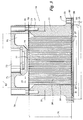
- the housing 10 contains a cluster of rods 30 with the length 31 of each of the rods of the cluster 30 being equal to the length of the housing 10.
- the length 31 will be in the range of 3" and the diameter 33 of each of the rods in the cluster 30 will be approximately .125".
- the diameter of the rods of the cluster 30 may be varied considerably. Smaller diameter rods will provide greater contour accuracy while larger diameter rods will provide a longer lasting tool.
- the bottom ends 37 of the individual rods of the cluster 30 will be rounded to further enhance contour accuracy.
- a lubricant 39 such as oil, water or other mildly lubricating substance, may be provided in the housing 10 to assure that the rods of the cluster 30 do not bind against each other or against the inner surface of the cylindrical wall 11 as the rods move unidirectionally in the housing 10.
- the cluster of rods 30 will include a sufficient number of rods to restrict non-longitudinal movement.
- the rods of the cluster 30 will be made of a plastic material, preferably Delrin.
- the cluster of rods 30 is maintained within the housing 10 by a top diaphragm 50 and a bottom diaphragm 60.
- the top diaphragm 50 has a diameter 51 substantially equal to the outer diameter of the cylindrical wall 11 and is provided with apertures 53 which align with the upper tap holes 17 in the cylindrical wall 11.
- the bottom diaphragm 60 has a diameter 61 which is substantially equal to the outer diameter of the flange 13 and has a plurality of apertures 63 aligned with the lower tap holes 19 in the flange 13.
- the diaphragms 50 and 60 are preferably made of a silicon elastomer material which, in an unstressed condition, will lie in a planar relationship across the upper and lower ends of the housing 10.
- the upper diaphragm 50 is sandwiched in place against the upper face of the housing 10 by a pneumatic cap 70 which consists essentially of a cylindrical body 71 having an outer diameter substantially equal to the outer diameter of the cylindrical wall 11 of the housing 10.
- a socket 73 is provided in the upper face of the pneumatic cap 70 for coupling the tool to the chuck of a surface enhancing machine (not shown).
- An annular air chamber or passage 75 is provided in the lower face of the cap 70 and defines an interior central land 77.
- a space 99 extends between the land 77 and the upper diaphragm 50 when the cap 70 is seated on the diaphragm 50.
- Apertures 81 are provided longitudinally in the periphery of the cap 70 which align with the upper tap holes 17 in the housing 10.
- the diameter 83 of the air chamber or passage 75 is preferably greater than the inner diameter 23 of the housing 10 and less than the outer diameter 21 of the bevel 15 in the housing 10.
- An air inlet port 85 is provided through the wall of the cap 70 to provide pneumatic access to the annular air chamber or passage 75.
- the caps 70 will be made of plastic, perhaps injection molded.
- the lower diaphragm 60 is sandwiched against the bottom face of the housing 10 by a bottom ring 90 of outer diameter substantially equal to the outer diameter of the flange 13 of the housing 10.
- the upper inner periphery of the ring 90 will have an annular bevel 91.
- the inner diameter 93 of the ring 90 is substantially greater than the inner diameter 23 of the housing 10.
- a plurality of apertures 95 are circumferentially spaced and longitudinally aligned through the ring 90 in alignment with the lower tap holes 19 in the flange 13 of the housing 10.
- the bottom ring 90 will be of plastic, perhaps injection molded.
- the lower diaphragm 60 is placed in planar relationship over the lower end of the housing 10 with the lower tap holes 19 of the housing 10 aligned with the apertures 63 in the ring 60.
- the bottom ring 90 is then laid over the bottom diaphragm 60 with its apertures 81 aligned with the apertures 63 in the bottom diaphragm 60. Screws (not shown) are then tightened through the bottom ring apertures 95 into the housing tap holes 19 to firmly clamp the bottom diaphragm 60 between the housing 10 and the bottom ring 90.
- a rod cluster 30 of suitable diameter 35 to maintain the rods in longitudinal alignment within the housing 10 is dropped into the housing 10 through its open upper end.
- a small amount of lubricant 39 is also introduced into the housing 10 to lubricate the contacting surfaces of the rods with each other and with the inner wall of the housing 10.
- the top diaphragm 50 is then laid in planar relationship over the upper end of the housing 10 with the diaphragm apertures 63 aligned with the upper housing tap holes 17.
- the cap 70 is then laid over the top diaphragm 50 with its apertures 81 aligned with the housing upper tap holes 17. Screws (not shown) are thus tightened through the cap apertures 81 into the housing upper tap holes 17 to clamp the top diaphragm 50 between the housing 10 and the cap 70.
- the completed tool can then be mounted for operation on a surface enhancing machine (not shown) by coupling the chuck (not shown) of the machine with the chuck socket 73 in the tool.
- a pad (not shown) having the desired abrasive quality can then be overlaid on the lower diaphragm 60 for contact with the lens (not shown) to be fined or polished.
- air under pressure is admitted into the chamber 75 in the cap 70 through the air inlet passage 85.
- the air pressure in an approximately 3" diameter housing will be in a range of 2 to 10 psi and preferably approximately 5 to 6psi.
- the air pressure in the chamber 75 causes the top diaphragm 50 to be depressed against the rod cluster 30.
- the multi-directional motion of the top diaphragm 50 in response to the pressure in the chamber 75 causes the diaphragm 50 to resiliently distort, imparting a unidirectional downward motion to the rods in the cluster 30.
- the bevel 15 in the housing 10 permits the distortion of the top diaphragm 50 to be more evenly distributed across the top of the rods and also prevents damage to the top diaphragm 50 resulting from an otherwise square or sharp corner at the contact point of the top diaphragm 50 with the housing 10.
- the lower or bottom diaphragm 60 is distorted by the unidirectional force applied by the rods in the cluster 30. Conformance of the bottom diaphragm 60 to the bottom ends of the rods in the cluster 30 is facilitated by the greater inner diameter 93 of the bottom ring 90.
- the bottom ring bevel 91 further facilitates this conformance as well as prevents sharp edges of the ring 90 from damaging the bottom diaphragm 60.
- the air pressure applied to the chamber 75 in the cap 70 is selected or regulated to suit the particular application of the tool.
- the diaphragm material should insure that lubricants and air do not escape their appropriate chambers. If the depth of the space 79 between the cap land 77 and the planar surface of the top diaphragm 50 is sufficient, the tool can be used to fine or polish concave or convex lenses by appropriate selection of the air pressure in the chamber, the top and bottom diaphragms operating in opposite fashion to that described herein to fine or polish a convex lens.
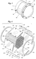
- an hexagonal rod cluster 130 such as that illustrated in Figure 4 is loaded into a tool having a housing 110, a top diaphragm 150, a bottom diaphragm 160, a pneumatic cap 170 and a bottom ring 190 which are substantially the same as their corresponding components in the tool described in relation to Figure 1.
- the rods are held in the hexagonal cluster 130 by six identical plates 141 of isometric trapezoidal cross-section.
- the beveled side edges 133 of the plates 131 are held in serial abutment by a pair of O-rings 145 which are stretchable to gird the plates 131 and are seated in slots 137 in the plates 131 which mate at the serial junction points.
- the length 139 of the rods is substantially equal to the length of the housing 110 while the length 141 of the plates 131 is less than the length of the interior wall 111 of the housing 110 from its bottom to its upper annular bevel 115.
- the rods of the cluster 130 will each have a diameter 143 of approximately .125 inches, though the diameter of the rods may be varied considerably, and the diameter 145 of the hexagonal cluster 130 will be such as to restrict non-longitudinal movement of the undivided rods. It is also preferred that the bottom ends 147 of the rods will be rounded to further enhance contour accuracy.
- the O-rings 135 are compressed between the inner wall 111 of the housing 110 and the trapezoidal plates 131 at the serial junction points of the plates 131 so as to firmly seat the hexagonal plate assembly in the housing 110.
- the hexagonal cluster configuration is preferred because it enhances the restriction of non-vertical motion of the rods within the assembly.
- other satisfactory cluster configurations can be achieved by adaptation of a suitable shell interiorly defining the contour of the cluster and exteriorly conformed to the interior of the housing.
- the shell components used are of plastic material, perhaps injection molded.
- the O-rings are preferably Neoprene.
- the interior of the housing itself can be contoured to provide the desired cluster cross-section without use of a special shell.
Landscapes
- Engineering & Computer Science (AREA)
- Mechanical Engineering (AREA)
- Grinding And Polishing Of Tertiary Curved Surfaces And Surfaces With Complex Shapes (AREA)
Applications Claiming Priority (2)
| Application Number | Priority Date | Filing Date | Title |
|---|---|---|---|
| US642351 | 1996-05-03 | ||
| US08/642,351 US5662518A (en) | 1996-05-03 | 1996-05-03 | Pneumatically assisted unidirectional conformal tool |
Publications (3)
| Publication Number | Publication Date |
|---|---|
| EP0804999A2 true EP0804999A2 (de) | 1997-11-05 |
| EP0804999A3 EP0804999A3 (de) | 1997-12-29 |
| EP0804999B1 EP0804999B1 (de) | 2002-04-03 |
Family
ID=24576211
Family Applications (1)
| Application Number | Title | Priority Date | Filing Date |
|---|---|---|---|
| EP97303024A Expired - Lifetime EP0804999B1 (de) | 1996-05-03 | 1997-05-02 | Pneumatisch anpassbares Einrichtungswerkzeug |
Country Status (3)
| Country | Link |
|---|---|
| US (1) | US5662518A (de) |
| EP (1) | EP0804999B1 (de) |
| DE (1) | DE69711479T2 (de) |
Cited By (3)
| Publication number | Priority date | Publication date | Assignee | Title |
|---|---|---|---|---|
| GB2360724A (en) * | 1999-12-01 | 2001-10-03 | Gerber Coburn Optical Inc | A lap retaining mechanism |
| US7503834B2 (en) | 2004-01-15 | 2009-03-17 | Carl Zeiss Vision Gmbh | Apparatus and a method of polishing an optical surface; an optical component; and a method of manufacturing a polishing tool |
| CN111774944A (zh) * | 2020-07-28 | 2020-10-16 | 大连理工大学 | 一种尖拱形蓝宝石整流罩磨抛一体化加工工装与方法 |
Families Citing this family (18)
| Publication number | Priority date | Publication date | Assignee | Title |
|---|---|---|---|---|
| US5928063A (en) * | 1996-05-03 | 1999-07-27 | Coburn Optical Industries, Inc. | Pneumatically assisted unidirectional arcuate diaphragm conformal tool |
| CA2260484C (en) * | 1998-01-30 | 2003-04-15 | Marc Y. Savoie | Method and apparatus for polishing ophthalmic lenses |
| US6050882A (en) * | 1999-06-10 | 2000-04-18 | Applied Materials, Inc. | Carrier head to apply pressure to and retain a substrate |
| US6110017A (en) * | 1999-09-08 | 2000-08-29 | Savoie; Marc Y. | Method and apparatus for polishing ophthalmic lenses |
| JP3753577B2 (ja) * | 1999-11-16 | 2006-03-08 | 株式会社荏原製作所 | 基板保持装置及び該基板保持装置を備えたポリッシング装置 |
| US6776695B2 (en) | 2000-12-21 | 2004-08-17 | Lam Research Corporation | Platen design for improving edge performance in CMP applications |
| US6607425B1 (en) * | 2000-12-21 | 2003-08-19 | Lam Research Corporation | Pressurized membrane platen design for improving performance in CMP applications |
| JP2004261954A (ja) * | 2003-02-14 | 2004-09-24 | Seiko Epson Corp | 研磨方法 |
| US20050202754A1 (en) * | 2003-05-16 | 2005-09-15 | Bechtold Mike J. | Method, apparatus, and tools for precision polishing of lenses and lens molds |
| US7018273B1 (en) | 2003-06-27 | 2006-03-28 | Lam Research Corporation | Platen with diaphragm and method for optimizing wafer polishing |
| US6955588B1 (en) | 2004-03-31 | 2005-10-18 | Lam Research Corporation | Method of and platen for controlling removal rate characteristics in chemical mechanical planarization |
| DE502005000312D1 (de) * | 2004-10-29 | 2007-02-22 | Schneider Gmbh & Co Kg | Polierwerkzeug mit mehreren Druckzonen |
| GB0802651D0 (en) * | 2008-02-14 | 2008-03-19 | 3M Innovative Properties Co | Methods and machines for lens deblocking |
| DE102010035526A1 (de) | 2010-08-25 | 2012-03-01 | Fraunhofer-Gesellschaft zur Förderung der angewandten Forschung e.V. | Feinbearbeitungsmembran und -werkzeug |
| CN105257673B (zh) * | 2015-11-02 | 2017-10-27 | 薛瑞华 | 球面垫片磨削夹具 |
| CN112247682B (zh) * | 2020-10-23 | 2021-12-28 | 江苏远业液压机械有限公司 | 一种液压机偶合配件的配研方法 |
| CN112894508B (zh) * | 2021-02-03 | 2022-03-15 | 江西博莱塑业有限公司 | 一种瓶盖的顶部打磨机器 |
| CN116117606B (zh) * | 2023-04-18 | 2023-08-08 | 河北昊天滤清器制造有限公司 | 一种滤清器壳体自动打磨设备 |
Family Cites Families (8)
| Publication number | Priority date | Publication date | Assignee | Title |
|---|---|---|---|---|
| DD47308A (de) * | ||||
| US2188365A (en) * | 1937-12-07 | 1940-01-30 | Leon B Lent | Grinding tool |
| NL248520A (de) * | 1959-02-18 | |||
| FR2293286A1 (fr) * | 1974-05-02 | 1976-07-02 | Le Prevost Jacques | Nouvelles methodes d'obtention d'outillages destines a l'usinage de materiaux optiques |
| DE3643914A1 (de) * | 1986-12-22 | 1988-06-30 | Zeiss Carl Fa | Verfahren und vorrichtung zum laeppen bzw. polieren optischer flaechen |
| FR2654027B1 (fr) * | 1989-11-06 | 1992-01-10 | Essilor Int | Outil de surfacage autoconformable. |
| JPH07509411A (ja) * | 1992-07-17 | 1995-10-19 | ミネソタ マイニング アンド マニュファクチャリング カンパニー | レンズ処理法とそれに使用する手段 |
| US5577950A (en) * | 1993-11-29 | 1996-11-26 | Coburn Optical Industries, Inc. | Conformal tool operating apparatus and process for an ophthalmic lens finer/polisher |
-
1996
- 1996-05-03 US US08/642,351 patent/US5662518A/en not_active Expired - Lifetime
-
1997
- 1997-05-02 DE DE69711479T patent/DE69711479T2/de not_active Expired - Fee Related
- 1997-05-02 EP EP97303024A patent/EP0804999B1/de not_active Expired - Lifetime
Cited By (4)
| Publication number | Priority date | Publication date | Assignee | Title |
|---|---|---|---|---|
| GB2360724A (en) * | 1999-12-01 | 2001-10-03 | Gerber Coburn Optical Inc | A lap retaining mechanism |
| US6375554B1 (en) | 1999-12-01 | 2002-04-23 | Gerber Coburn Optical Inc. | Retaining mechanism for lapping device |
| US7503834B2 (en) | 2004-01-15 | 2009-03-17 | Carl Zeiss Vision Gmbh | Apparatus and a method of polishing an optical surface; an optical component; and a method of manufacturing a polishing tool |
| CN111774944A (zh) * | 2020-07-28 | 2020-10-16 | 大连理工大学 | 一种尖拱形蓝宝石整流罩磨抛一体化加工工装与方法 |
Also Published As
| Publication number | Publication date |
|---|---|
| EP0804999A3 (de) | 1997-12-29 |
| EP0804999B1 (de) | 2002-04-03 |
| US5662518A (en) | 1997-09-02 |
| DE69711479D1 (de) | 2002-05-08 |
| DE69711479T2 (de) | 2002-12-19 |
Similar Documents
| Publication | Publication Date | Title |
|---|---|---|
| US5662518A (en) | Pneumatically assisted unidirectional conformal tool | |
| US5762546A (en) | Pneumatically assisted conformal tool for an ophthalmic lens finer/polisher | |
| US3886696A (en) | Mounting device for optical lenses | |
| EP0884135B1 (de) | Pneumatisch anpassbares Einrichtungswerkzeug mit bogenförmiger Membran | |
| US6932678B2 (en) | Polishing apparatus | |
| US5291692A (en) | Polishing work holder | |
| US6875090B2 (en) | Apparatus for finishing optical surfaces, including a pad compensation device | |
| US6106379A (en) | Semiconductor wafer carrier with automatic ring extension | |
| US5357716A (en) | Holding device for holding optical element to be ground | |
| KR20040071318A (ko) | 연마 방법 및 연마 장치 | |
| US20250222554A1 (en) | Retainer for the Processing of Optical Workpieces, in Particular Eyeglass Lenses | |
| US6527632B1 (en) | Lap having a layer conformable to curvatures of optical surfaces on lenses and a method for finishing optical surfaces | |
| EP0073873B1 (de) | Kontaktlinsen-Konstruktion | |
| JP2003266287A (ja) | 研磨治具および研磨パッド | |
| US7448942B2 (en) | Grinding method | |
| US7063604B2 (en) | Independent edge control for CMP carriers | |
| CA2260484C (en) | Method and apparatus for polishing ophthalmic lenses | |
| KR100930226B1 (ko) | 렌즈 연마장치 | |
| US20020102925A1 (en) | Surface polishing method and apparatus | |
| US3771265A (en) | Glass lens edging apparatus for sensing lens holding frames | |
| US2257474A (en) | Honing head | |
| CN101352825A (zh) | 研磨装置 | |
| US6749494B2 (en) | Conditioning tool | |
| US5542444A (en) | Valve and method of using | |
| CN213917726U (zh) | 一种高效抛光磨头 |
Legal Events
| Date | Code | Title | Description |
|---|---|---|---|
| PUAI | Public reference made under article 153(3) epc to a published international application that has entered the european phase |
Free format text: ORIGINAL CODE: 0009012 |
|
| AK | Designated contracting states |
Kind code of ref document: A2 Designated state(s): DE FR GB |
|
| PUAL | Search report despatched |
Free format text: ORIGINAL CODE: 0009013 |
|
| AK | Designated contracting states |
Kind code of ref document: A3 Designated state(s): DE FR GB |
|
| 17P | Request for examination filed |
Effective date: 19980313 |
|
| 17Q | First examination report despatched |
Effective date: 19990330 |
|
| GRAG | Despatch of communication of intention to grant |
Free format text: ORIGINAL CODE: EPIDOS AGRA |
|
| RIN1 | Information on inventor provided before grant (corrected) |
Inventor name: KRUIS, FRITZ R. Inventor name: JAMES, MICHAEL D. |
|
| RAP1 | Party data changed (applicant data changed or rights of an application transferred) |
Owner name: GERBER COBURN OPTICAL, INC. |
|
| GRAG | Despatch of communication of intention to grant |
Free format text: ORIGINAL CODE: EPIDOS AGRA |
|
| GRAH | Despatch of communication of intention to grant a patent |
Free format text: ORIGINAL CODE: EPIDOS IGRA |
|
| GRAH | Despatch of communication of intention to grant a patent |
Free format text: ORIGINAL CODE: EPIDOS IGRA |
|
| REG | Reference to a national code |
Ref country code: GB Ref legal event code: IF02 |
|
| GRAA | (expected) grant |
Free format text: ORIGINAL CODE: 0009210 |
|
| AK | Designated contracting states |
Kind code of ref document: B1 Designated state(s): DE FR GB |
|
| REF | Corresponds to: |
Ref document number: 69711479 Country of ref document: DE Date of ref document: 20020508 |
|
| ET | Fr: translation filed | ||
| PLBE | No opposition filed within time limit |
Free format text: ORIGINAL CODE: 0009261 |
|
| STAA | Information on the status of an ep patent application or granted ep patent |
Free format text: STATUS: NO OPPOSITION FILED WITHIN TIME LIMIT |
|
| 26N | No opposition filed |
Effective date: 20030106 |
|
| REG | Reference to a national code |
Ref country code: GB Ref legal event code: 732E |
|
| PGFP | Annual fee paid to national office [announced via postgrant information from national office to epo] |
Ref country code: DE Payment date: 20080508 Year of fee payment: 12 |
|
| PGFP | Annual fee paid to national office [announced via postgrant information from national office to epo] |
Ref country code: GB Payment date: 20080507 Year of fee payment: 12 |
|
| GBPC | Gb: european patent ceased through non-payment of renewal fee |
Effective date: 20090502 |
|
| REG | Reference to a national code |
Ref country code: FR Ref legal event code: ST Effective date: 20100129 |
|
| PG25 | Lapsed in a contracting state [announced via postgrant information from national office to epo] |
Ref country code: FR Free format text: LAPSE BECAUSE OF NON-PAYMENT OF DUE FEES Effective date: 20090602 |
|
| PGFP | Annual fee paid to national office [announced via postgrant information from national office to epo] |
Ref country code: FR Payment date: 20080514 Year of fee payment: 12 |
|
| PG25 | Lapsed in a contracting state [announced via postgrant information from national office to epo] |
Ref country code: GB Free format text: LAPSE BECAUSE OF NON-PAYMENT OF DUE FEES Effective date: 20090502 |
|
| PG25 | Lapsed in a contracting state [announced via postgrant information from national office to epo] |
Ref country code: DE Free format text: LAPSE BECAUSE OF NON-PAYMENT OF DUE FEES Effective date: 20091201 |