EP0804978A1 - Twisting or bending machine for making either mono or double winding coil springs - Google Patents
Twisting or bending machine for making either mono or double winding coil springs Download PDFInfo
- Publication number
- EP0804978A1 EP0804978A1 EP97830199A EP97830199A EP0804978A1 EP 0804978 A1 EP0804978 A1 EP 0804978A1 EP 97830199 A EP97830199 A EP 97830199A EP 97830199 A EP97830199 A EP 97830199A EP 0804978 A1 EP0804978 A1 EP 0804978A1
- Authority
- EP
- European Patent Office
- Prior art keywords
- wire
- feeding direction
- transport unit
- machine according
- winding tool
- Prior art date
- Legal status (The legal status is an assumption and is not a legal conclusion. Google has not performed a legal analysis and makes no representation as to the accuracy of the status listed.)
- Granted
Links
Images


Classifications
-
- B—PERFORMING OPERATIONS; TRANSPORTING
- B21—MECHANICAL METAL-WORKING WITHOUT ESSENTIALLY REMOVING MATERIAL; PUNCHING METAL
- B21F—WORKING OR PROCESSING OF METAL WIRE
- B21F35/00—Making springs from wire
-
- B—PERFORMING OPERATIONS; TRANSPORTING
- B21—MECHANICAL METAL-WORKING WITHOUT ESSENTIALLY REMOVING MATERIAL; PUNCHING METAL
- B21F—WORKING OR PROCESSING OF METAL WIRE
- B21F3/00—Coiling wire into particular forms
- B21F3/02—Coiling wire into particular forms helically
- B21F3/04—Coiling wire into particular forms helically externally on a mandrel or the like
Definitions
- the present invention relates to a twisting or bending machine, which has been specifically designed for making either mono or double winding coil springs.
- twisters or benders by which the wire material to be used for making the coil spring is pressed against a suitable winding tool, causing the wire material to be progressively deformed so as to form the spring with its conventional coil or helical configuration.
- the pressing force on the wire as the spring is formed is supplied by a wire carrying or transport unit, substantially comprising a roller assembly including a plurality of rollers entraining the wire material along a wire material feeding direction and causing said wire material to pass through a wire guiding element facing the winding tool.
- the wire material transport unit in particular, is generally stationary with respect to the spindle supporting the winding tool or it can be displaced along a direction parallel to the wire feeding direction.
- the aim of the present invention is to overcome the above mentioned problem, by providing a twisting or bending machine which has been specifically designed for making coil springs, which allows to change, depending on requirements, the contact point of the wire material and the winding tool.
- a main object of the present invention is to provide such a machine which is provided with a very high operating flexibility characteristic.
- Another object of the present invention is to provide such a machine which is specifically adapted to make different shape coil springs, without requiring the coil spring winding tool to be replaced.
- Yet another object of the present invention is to provide such a machine which is very reliable and safe in operation.
- a twisting or bending machine specifically designed for making coil springs, either of a mono or a double winding type, which comprises a wire transport unit, including a roller assembly for entraining the wire along a wire feeding direction.
- Said wire transport unit is arranged in front of a winding tool, which is adapted to bend said wire, said machine being characterized in that said wire transport unit can he driven, with respect to said winding tool, either in parallel to the wire winding direction as well as transversely of said wire winding direction, in order to cause the contact point of the wire and winding tool to change.
- the transport or carrying unit 2 comprises an assembly of rollers 4, said rollers 4 being rotatively driven about respective rotary axes and cooperating with one another in order to cause the wire 3 to be driven along a wire driving or feeding direction.
- the wire transport unit 2 comprises, moreover, a wire guiding element 5 provided with a wire passage, extending parallel to the wire feeding direction, and facing a wire winding tool 6 comprising, in the embodiment shown in figures 1 to 3, a winding spindle or shaft, having a substantially vertical axis, which is rotatively driven about its axis so as to cause the wire 3 to be progressively wound about said shaft or mandrel.
- a cutting blade 7 is arranged, specifically provided for cutting the wire 3 at the end of a spring making operation.
- the wire transport unit 2 is supported by the machine base 1 by means of two pairs of cross-guiding element 8, each of which comprises a bottom guiding element 9 extending perpendicular to the wire 3 feeding direction, a middle guiding element 10 and a top guiding element 11 arranged parallel to the wire 3 feeding direction, thereby the wire 3 transport unit can be driven either in a direction parallel to the wire 3 feeding direction or in a direction perpendicular to said wire 3 feeding direction, in a substantially horizontal plane.
- the driving of the wire transport unit 2 along the guiding elements 8 is obtained, in a direction parallel to the wire 3 feeding direction, for example by a servomotor 12 which, through suitable transmission means, comprising, for example, a belt 13 and a screw-screw nut assembly, drive the transport unit 2.
- the displacement or driving of the wire transport unit 2 in a direction perpendicular to the wire 3 feeding direction can be obtained, in a like manner, by known driving means which, for simplicity, have not been specifically shown.
- the wire transport unit 2 instead of being supported by the machine base 1 through cross guiding elements, is pivoted to said machine base by a pivot pin 20, to a vertical axis 20a, i.e. perpendicular to the wire 3 feeding direction in the wire transport unit 2.
- the driving of the transport unit 2, i.e. the swinging thereof about the axis 20a, with respect to the machine base 1, can be obtained by a servomotor, with a screw or screw-nut transmission, generally indicated by the reference number 21, operating on the transport unit 2 so as to cause the latter to partially turn about the rotary axis 20a.
- FIGs 2 and 3, as well as figures 5 and 6, clearly illustrates this multiple displacement or driving of the wire transport unit 2 with respect to the wire winding tool, in order to make two springs having opposite winding directions.
- the mandrel or spindle 30 has the axis 30a extending in a vertical direction and is supported both rotatably about said axis 30a and parallel to said axis 30a, by supporting framework 34.
- a threaded shaft 35 is arranged, also having a vertical axis, and engaging with a nut screw 36 rigid with a movable block 37 supporting rotatably the spindle 30 so as to allow said spindle to turn about its pivot axis 30a.
- the threaded shaft 35 can be driven by an electric motor 38 so as to cause the block 37 and, accordingly, the spindle 30, to turn parallel to the pivot axis 30a.
- the spindle 30 can be rotatively driven about its pivot axis 30a by a gear wheel 41 and 42 transmission assembly, the gear wheels 41 and 42 of which are housed inside the supporting framework 34.
- the latter is slidably mounted on two guides 43a and 43b which are horizontally arranged and extend perpendicular to the wire 3 feeding direction 33.
- the driving of the supporting framework 34 and, accordingly, of the spindle or mandrel 30 in a horizontal direction, or the driving of said guide elements 43a and 43b is obtained, in a like manner to that disclosed thereinabove, by means of a threaded shaft 44 engaging in a screw nut rigid with the supporting framework 34.
- the spindle 30 can be driven both vertically, i.e. in a direction parallel to the pivot axis 30a thereof, and accordingly perpendicular to the wire feeding direction 33, preferably a horizontal direction, and in parallel to the guiding elements 43a and 43b, also horizontally extending, but perpendicular to the wire feeding direction 33 so as to change, depending on requirements, the contact point of the wire being supplied by the wire guiding element 5 and the winding tool 31.
- the winding tool 31 in particular, is supported by the spindle or mandrel 30 through a tool holder element 45 which, as shown in figure 7, can be turned, in a per se known manner, about the rotary axis thereof, extending parallel to or even coinciding with the wire feeding direction 33.
- the spindle 5 can be either a fixed type of spindle, or it can turn about its pivot axis, coinciding with the axis of the wire 3 and, moreover, said spindle can also be provided with wire gripping means, for gripping the wire during the rotation thereof, so as to increase the working capabilities of the twisting and bending machine according to the present invention.
- the used materials, as well as the contingent size and shapes can be any, depending on requirements.
Abstract
Description
- The present invention relates to a twisting or bending machine, which has been specifically designed for making either mono or double winding coil springs.
- As is known, for making coil springs are at present used suitable coil spring winding machines, the so called twisters or benders, by which the wire material to be used for making the coil spring is pressed against a suitable winding tool, causing the wire material to be progressively deformed so as to form the spring with its conventional coil or helical configuration.
- The pressing force on the wire as the spring is formed, is supplied by a wire carrying or transport unit, substantially comprising a roller assembly including a plurality of rollers entraining the wire material along a wire material feeding direction and causing said wire material to pass through a wire guiding element facing the winding tool.
- The wire material transport unit, in particular, is generally stationary with respect to the spindle supporting the winding tool or it can be displaced along a direction parallel to the wire feeding direction.
- Thus, prior coil spring winding machine have an operating flexibility which is comparatively law.
- Accordingly, the aim of the present invention is to overcome the above mentioned problem, by providing a twisting or bending machine which has been specifically designed for making coil springs, which allows to change, depending on requirements, the contact point of the wire material and the winding tool.
- Within the scope of the above mentioned aim, a main object of the present invention is to provide such a machine which is provided with a very high operating flexibility characteristic.
- Another object of the present invention is to provide such a machine which is specifically adapted to make different shape coil springs, without requiring the coil spring winding tool to be replaced.
- Yet another object of the present invention Is to provide such a machine which is very reliable and safe in operation.
- According to one aspect of the present invention, the above mentioned aim and objects, and yet other objects, which will become more apparent hereinafter, are achieved by a twisting or bending machine, specifically designed for making coil springs, either of a mono or a double winding type, which comprises a wire transport unit, including a roller assembly for entraining the wire along a wire feeding direction.
- Said wire transport unit is arranged in front of a winding tool, which is adapted to bend said wire, said machine being characterized in that said wire transport unit can he driven, with respect to said winding tool, either in parallel to the wire winding direction as well as transversely of said wire winding direction, in order to cause the contact point of the wire and winding tool to change.
- Further characteristics and advantages of the twisting and bending machine according to the present invention will become more apparent hereinafter from the following detailed disclosure of some preferred embodiments of said machine which are illustrated, by way of a merely indicative, but not limitative example, in the figures of the accompanying drawings, where:
- Figure 1 is a schematic side elevation view illustrating a first embodiment of the twisting and bending machine according to the present invention;
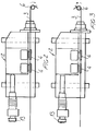
- Figures 2 and 3 are schematic views illustrating the first embodiment of the twisting and bending machine according to the present invention, in a top plan view, the wire transport unit being shown in two different operating positions with respect to the wire winding tool;
- Figure 4 is a further schematic side elevation and partially cross-sectioned view illustrating a second embodiment of the twisting and bending machine according to the present invention;
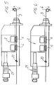
- Figures 5 and 6 are respective top plan views illustrating the second embodiment of the subject machine, the wire transport unit being shown in two different operating positions with respect to the winding tool;
- Figure 7 is a further schematic side elevation and partially sectioned view illustrating a further modified embodiment of the twisting and bending machine according to the present invention; and
- Figure 8 is a front partially cross-sectioned view illustrating the twisting and bending machine shown in figure 7.
- With reference to figures 1 to 3, the twisting and bending machine according a first embodiment of the present invention comprises a base 1, supporting a
feeding unit 2 for feeding awire material 3 to be processed by deformation in order to make coil springs. - More specifically, the transport or carrying
unit 2 comprises an assembly ofrollers 4, saidrollers 4 being rotatively driven about respective rotary axes and cooperating with one another in order to cause thewire 3 to be driven along a wire driving or feeding direction. - The
wire transport unit 2 comprises, moreover, awire guiding element 5 provided with a wire passage, extending parallel to the wire feeding direction, and facing awire winding tool 6 comprising, in the embodiment shown in figures 1 to 3, a winding spindle or shaft, having a substantially vertical axis, which is rotatively driven about its axis so as to cause thewire 3 to be progressively wound about said shaft or mandrel. - Between the
wire guiding element 5 and the wire winding tool 6 a cutting blade 7 is arranged, specifically provided for cutting thewire 3 at the end of a spring making operation. - As shown, the
wire transport unit 2 is supported by the machine base 1 by means of two pairs ofcross-guiding element 8, each of which comprises abottom guiding element 9 extending perpendicular to thewire 3 feeding direction, amiddle guiding element 10 and a top guidingelement 11 arranged parallel to thewire 3 feeding direction, thereby thewire 3 transport unit can be driven either in a direction parallel to thewire 3 feeding direction or in a direction perpendicular to saidwire 3 feeding direction, in a substantially horizontal plane. - The driving of the
wire transport unit 2 along the guidingelements 8 is obtained, in a direction parallel to thewire 3 feeding direction, for example by aservomotor 12 which, through suitable transmission means, comprising, for example, abelt 13 and a screw-screw nut assembly, drive thetransport unit 2. - The displacement or driving of the
wire transport unit 2 in a direction perpendicular to thewire 3 feeding direction can be obtained, in a like manner, by known driving means which, for simplicity, have not been specifically shown. - According to the modified embodiment shown in figures 4 to 6, the
wire transport unit 2, instead of being supported by the machine base 1 through cross guiding elements, is pivoted to said machine base by apivot pin 20, to a vertical axis 20a, i.e. perpendicular to thewire 3 feeding direction in thewire transport unit 2. - In this modified embodiment, the driving of the
transport unit 2, i.e. the swinging thereof about the axis 20a, with respect to the machine base 1, can be obtained by a servomotor, with a screw or screw-nut transmission, generally indicated by thereference number 21, operating on thetransport unit 2 so as to cause the latter to partially turn about the rotary axis 20a. - Thus, by the above possible displacements of the
wire transport unit 2, with respect to thewire winding tool 6, both in a parallel direction and in a perpendicular direction to thewire 3 feeding direction, it is possible to change the contact point of the wire with thewinding tool 6, thereby, by a single winding tool, it will be possible to make several different coil springs, depending on requirements. - Figures 2 and 3, as well as figures 5 and 6, clearly illustrates this multiple displacement or driving of the
wire transport unit 2 with respect to the wire winding tool, in order to make two springs having opposite winding directions. - In the inventive embodiment shown in figures 7 and 8, it is provided to drive the
winding tool 31 supporting mandrel orspindle 30, in a direction which is transversal of thewire 3feeding direction 33, saidwire 3 being supplied by thewire guiding element 5 of thewire transport unit 2. - As shown in the above mentioned figures, the mandrel or
spindle 30 has the axis 30a extending in a vertical direction and is supported both rotatably about said axis 30a and parallel to said axis 30a, by supportingframework 34. - Inside the supporting framework 34 a threaded
shaft 35 is arranged, also having a vertical axis, and engaging with anut screw 36 rigid with amovable block 37 supporting rotatably thespindle 30 so as to allow said spindle to turn about its pivot axis 30a. - As shown, the threaded
shaft 35 can be driven by anelectric motor 38 so as to cause theblock 37 and, accordingly, thespindle 30, to turn parallel to the pivot axis 30a. - In particular, the
spindle 30 can be rotatively driven about its pivot axis 30a by agear wheel gear wheels framework 34. - The latter is slidably mounted on two
guides wire 3feeding direction 33. - The driving of the supporting
framework 34 and, accordingly, of the spindle ormandrel 30 in a horizontal direction, or the driving of saidguide elements shaft 44 engaging in a screw nut rigid with the supportingframework 34. - Thus, the
spindle 30 can be driven both vertically, i.e. in a direction parallel to the pivot axis 30a thereof, and accordingly perpendicular to thewire feeding direction 33, preferably a horizontal direction, and in parallel to the guidingelements wire feeding direction 33 so as to change, depending on requirements, the contact point of the wire being supplied by thewire guiding element 5 and thewinding tool 31. - The
winding tool 31, in particular, is supported by the spindle ormandrel 30 through atool holder element 45 which, as shown in figure 7, can be turned, in a per se known manner, about the rotary axis thereof, extending parallel to or even coinciding with thewire feeding direction 33. - In this connection it should be pointed out that the
spindle 5 can be either a fixed type of spindle, or it can turn about its pivot axis, coinciding with the axis of thewire 3 and, moreover, said spindle can also be provided with wire gripping means, for gripping the wire during the rotation thereof, so as to increase the working capabilities of the twisting and bending machine according to the present invention. - From the above disclosure and from the figures of the accompanying drawings, it should be apparent that the invention fully achieves the intended aim and objects.
- In particular, the fact is to be pointed out that a wire twisting and bending machine has been provided which, owing to the possibility of changing the contact point of the wire material and wire winding tool, has a very flexible type of operation, adapted to meet all of the processing requirements for making coil springs.
- The invention, as disclosed, is susceptible to several variations and modifications, all of which will come within the inventive idea scope.
- Moreover, all of the details can be replaced by other technically equivalent elements.
- In practicing the invention, the used materials, as well as the contingent size and shapes, can be any, depending on requirements.
Claims (10)
- A wire twisting or bending machine, specifically designed for making coil springs, either of a mono or a double winding type, comprising a wire transport unit including an assembly of rollers for entraining the wire along a wire feeding direction, said wire transport unit being arranged in front of a wire winding tool adapted to bend said wire, characterized in that said wire transport unit can be controllably driven, with respect to said wire winding tool, both in parallel to and transversally of the wire feeding direction in order to cause the contact point of the wire and wire winding tool to change.
- A machine according to Claim 1, characterized in that said wire transport unit is mounted on cross slides supported by the base of said machine, driving means being moreover provided for driving said wire transport unit along two legs of said slides, said legs being respectively arranged parallel and perpendicular to said wire feeding direction.
- A machine according to Claim 1, characterized in that said wire transport unit is pivoted to said base of said machine about a pivot axis which is substantially perpendicular to said wire feeding direction.
- A machine according to one or more of the preceding claims, characterized in that said wire transport unit comprises a wire guiding element in which a passage for said wire is defined, said wire passage extending along the wire feeding direction, and in that said wire guiding element can be controllably turned about the axis of said wire, extending along said wire feeding direction.
- A machine according to one or more of the preceding claims, characterized in that said wire guiding element is provided with wire gripping means.
- A machine according to one or more of the preceding claims, characterized in that said wire winding tool is supported on a tool spindle, which can be controllably turned about a pivot axis perpendicular to said wire feeding direction.
- A machine according to one or more of the preceding claims, characterized in that said wire winding tool is supported on a controllably rotatable tool holder, which can be controllably turned, with respect to said spindle, about an axis parallel to said wire feeding direction.
- A machine according to one or more of the preceding claims, characterized in that said spindle can be controllably driven along a first driving direction transversal of said wire feeding direction.
- A machine according to one or more of the preceding claims, characterized in that said spindle can be controllably driven along a second driving direction, which is substantially perpendicular to said wire feeding direction and substantially perpendicular to said first driving direction.
- A wire twisting or bending machine, specifically designed for making coil springs, either of a mono or a double winding type, according to one or more of the preceding claims, and substantially as broadly disclosed and illustrated for the intended aim and objects.
Applications Claiming Priority (2)
| Application Number | Priority Date | Filing Date | Title |
|---|---|---|---|
| ITMI960856 | 1996-05-02 | ||
| IT96MI000856A IT1282393B1 (en) | 1996-05-02 | 1996-05-02 | TWISTING OR BENDING MACHINE PARTICULARLY DESIGNED FOR THE MANUFACTURE OF SIMPLE AND DOUBLE TORSION SPRINGS |
Publications (2)
| Publication Number | Publication Date |
|---|---|
| EP0804978A1 true EP0804978A1 (en) | 1997-11-05 |
| EP0804978B1 EP0804978B1 (en) | 2002-10-02 |
Family
ID=11374179
Family Applications (1)
| Application Number | Title | Priority Date | Filing Date |
|---|---|---|---|
| EP97830199A Expired - Lifetime EP0804978B1 (en) | 1996-05-02 | 1997-04-30 | Twisting or bending machine for making either mono or double winding coil springs |
Country Status (3)
| Country | Link |
|---|---|
| EP (1) | EP0804978B1 (en) |
| DE (1) | DE69715953T2 (en) |
| IT (1) | IT1282393B1 (en) |
Cited By (3)
| Publication number | Priority date | Publication date | Assignee | Title |
|---|---|---|---|---|
| EP1637251A1 (en) * | 2004-09-21 | 2006-03-22 | David Wu | Wire feeder driving mechanism for spring manufacturing machine |
| CN100353088C (en) * | 2004-09-02 | 2007-12-05 | 吴国城 | Thread spool driving structure for spring machine |
| CN103781570A (en) * | 2011-04-12 | 2014-05-07 | 瓦菲奥斯股份公司 | Method for producing springs and spring machine for carrying out the method |
Families Citing this family (2)
| Publication number | Priority date | Publication date | Assignee | Title |
|---|---|---|---|---|
| DE102007031514A1 (en) | 2007-07-06 | 2009-01-08 | Wafios Ag | Wire forming machine |
| CN108372262B (en) * | 2018-03-01 | 2020-04-03 | 芜湖市海联机械设备有限公司 | Automatic spring coiling machine |
Citations (5)
| Publication number | Priority date | Publication date | Assignee | Title |
|---|---|---|---|---|
| US3472051A (en) * | 1967-03-17 | 1969-10-14 | Charles R Bergevin | Spring coiling machine |
| JPS59163044A (en) * | 1983-03-09 | 1984-09-14 | Chuo Spring Co Ltd | Device for producing hot coil spring |
| EP0136554A2 (en) * | 1983-09-01 | 1985-04-10 | Morita Iron Works Co., Ltd. | Method of making a coil spring and apparatus therefor |
| DE3912244A1 (en) * | 1989-04-14 | 1990-10-18 | Pulzer Biegetechnik Gmbh | Device for bending cylindrical materials into spiral shape - by feeding material to rotating former by grooved roller which moves along axis of former |
| DE4447253A1 (en) * | 1994-06-30 | 1996-01-11 | Itaya Seisakusho | Spiral spring mfg device |
-
1996
- 1996-05-02 IT IT96MI000856A patent/IT1282393B1/en active IP Right Grant
-
1997
- 1997-04-30 EP EP97830199A patent/EP0804978B1/en not_active Expired - Lifetime
- 1997-04-30 DE DE69715953T patent/DE69715953T2/en not_active Expired - Lifetime
Patent Citations (5)
| Publication number | Priority date | Publication date | Assignee | Title |
|---|---|---|---|---|
| US3472051A (en) * | 1967-03-17 | 1969-10-14 | Charles R Bergevin | Spring coiling machine |
| JPS59163044A (en) * | 1983-03-09 | 1984-09-14 | Chuo Spring Co Ltd | Device for producing hot coil spring |
| EP0136554A2 (en) * | 1983-09-01 | 1985-04-10 | Morita Iron Works Co., Ltd. | Method of making a coil spring and apparatus therefor |
| DE3912244A1 (en) * | 1989-04-14 | 1990-10-18 | Pulzer Biegetechnik Gmbh | Device for bending cylindrical materials into spiral shape - by feeding material to rotating former by grooved roller which moves along axis of former |
| DE4447253A1 (en) * | 1994-06-30 | 1996-01-11 | Itaya Seisakusho | Spiral spring mfg device |
Non-Patent Citations (1)
| Title |
|---|
| PATENT ABSTRACTS OF JAPAN vol. 009, no. 014 (M - 352) 22 January 1985 (1985-01-22) * |
Cited By (4)
| Publication number | Priority date | Publication date | Assignee | Title |
|---|---|---|---|---|
| CN100353088C (en) * | 2004-09-02 | 2007-12-05 | 吴国城 | Thread spool driving structure for spring machine |
| EP1637251A1 (en) * | 2004-09-21 | 2006-03-22 | David Wu | Wire feeder driving mechanism for spring manufacturing machine |
| CN103781570A (en) * | 2011-04-12 | 2014-05-07 | 瓦菲奥斯股份公司 | Method for producing springs and spring machine for carrying out the method |
| US9370817B2 (en) | 2011-04-12 | 2016-06-21 | Wafios Ag | Method and system for programming the control of a multiaxis forming machine and forming machine |
Also Published As
| Publication number | Publication date |
|---|---|
| DE69715953D1 (en) | 2002-11-07 |
| ITMI960856A1 (en) | 1997-11-02 |
| IT1282393B1 (en) | 1998-03-20 |
| ITMI960856A0 (en) | 1996-05-02 |
| EP0804978B1 (en) | 2002-10-02 |
| DE69715953T2 (en) | 2003-08-14 |
Similar Documents
| Publication | Publication Date | Title |
|---|---|---|
| EP0198984B1 (en) | Bending apparatus | |
| US5363681A (en) | Apparatus for shaping wire | |
| CA1301610C (en) | Bending machine | |
| US4947670A (en) | Universal automatic spring-making machine | |
| EP0044464A2 (en) | Method of forming a coil spring | |
| EP1461172B1 (en) | Two wire spring making machine and method | |
| EP0804978B1 (en) | Twisting or bending machine for making either mono or double winding coil springs | |
| US6044682A (en) | Wire product manufacturing apparatus | |
| CN112756503A (en) | Wire bending forming machine and working method thereof | |
| CN112828211A (en) | Large-pitch large-diameter special-shaped spring machine | |
| JP5406457B2 (en) | Spring making machine | |
| JP3458031B2 (en) | Spring forming machine | |
| US20050103080A1 (en) | Method and machine for simultaneous and parallel production of similar products, through straightening and bending of wires, wire rods, metal tubes or other material of prismatic cross section | |
| US3735625A (en) | Apparatus for producing helical wires, rods, bars and the like | |
| US3375692A (en) | Wire working apparatus | |
| CN112708737A (en) | Method for preventing tube wall of metal material from being scratched in tube annealing furnace | |
| CN215467732U (en) | Straightening device for wire processing | |
| US890907A (en) | Wire straightening and coiling machine. | |
| US4177662A (en) | Machine for the manufacture of axially prestressed coils from strip | |
| US3238754A (en) | Method and machine for making noncumulative force springs | |
| EP0056330B1 (en) | Spring coiling machine with improved cut-off means | |
| EP0950445A2 (en) | Apparatus and method for making coil springs | |
| JPS6245764Y2 (en) | ||
| SU1240492A1 (en) | Automatic machine for making bent articles of wire | |
| EP0538763A1 (en) | Device for correcting the straightening of iron rods and the like |
Legal Events
| Date | Code | Title | Description |
|---|---|---|---|
| PUAI | Public reference made under article 153(3) epc to a published international application that has entered the european phase |
Free format text: ORIGINAL CODE: 0009012 |
|
| AK | Designated contracting states |
Kind code of ref document: A1 Designated state(s): DE FR GB |
|
| 17P | Request for examination filed |
Effective date: 19980302 |
|
| 17Q | First examination report despatched |
Effective date: 20011024 |
|
| GRAG | Despatch of communication of intention to grant |
Free format text: ORIGINAL CODE: EPIDOS AGRA |
|
| GRAG | Despatch of communication of intention to grant |
Free format text: ORIGINAL CODE: EPIDOS AGRA |
|
| GRAH | Despatch of communication of intention to grant a patent |
Free format text: ORIGINAL CODE: EPIDOS IGRA |
|
| GRAH | Despatch of communication of intention to grant a patent |
Free format text: ORIGINAL CODE: EPIDOS IGRA |
|
| GRAA | (expected) grant |
Free format text: ORIGINAL CODE: 0009210 |
|
| AK | Designated contracting states |
Kind code of ref document: B1 Designated state(s): DE FR GB |
|
| REG | Reference to a national code |
Ref country code: GB Ref legal event code: FG4D |
|
| REF | Corresponds to: |
Ref document number: 69715953 Country of ref document: DE Date of ref document: 20021107 |
|
| PLBE | No opposition filed within time limit |
Free format text: ORIGINAL CODE: 0009261 |
|
| STAA | Information on the status of an ep patent application or granted ep patent |
Free format text: STATUS: NO OPPOSITION FILED WITHIN TIME LIMIT |
|
| 26N | No opposition filed |
Effective date: 20030703 |
|
| PGFP | Annual fee paid to national office [announced via postgrant information from national office to epo] |
Ref country code: GB Payment date: 20040607 Year of fee payment: 8 |
|
| PG25 | Lapsed in a contracting state [announced via postgrant information from national office to epo] |
Ref country code: GB Free format text: LAPSE BECAUSE OF NON-PAYMENT OF DUE FEES Effective date: 20050430 |
|
| GBPC | Gb: european patent ceased through non-payment of renewal fee |
Effective date: 20050430 |
|
| PGFP | Annual fee paid to national office [announced via postgrant information from national office to epo] |
Ref country code: FR Payment date: 20140430 Year of fee payment: 18 |
|
| PGFP | Annual fee paid to national office [announced via postgrant information from national office to epo] |
Ref country code: DE Payment date: 20150513 Year of fee payment: 19 |
|
| REG | Reference to a national code |
Ref country code: FR Ref legal event code: ST Effective date: 20151231 |
|
| PG25 | Lapsed in a contracting state [announced via postgrant information from national office to epo] |
Ref country code: FR Free format text: LAPSE BECAUSE OF NON-PAYMENT OF DUE FEES Effective date: 20150430 |
|
| REG | Reference to a national code |
Ref country code: DE Ref legal event code: R119 Ref document number: 69715953 Country of ref document: DE |
|
| PG25 | Lapsed in a contracting state [announced via postgrant information from national office to epo] |
Ref country code: DE Free format text: LAPSE BECAUSE OF NON-PAYMENT OF DUE FEES Effective date: 20161101 |