EP0804897B1 - Floor cleaning machine, in particular vacuum scrubbing machine - Google Patents
Floor cleaning machine, in particular vacuum scrubbing machine Download PDFInfo
- Publication number
- EP0804897B1 EP0804897B1 EP97105200A EP97105200A EP0804897B1 EP 0804897 B1 EP0804897 B1 EP 0804897B1 EP 97105200 A EP97105200 A EP 97105200A EP 97105200 A EP97105200 A EP 97105200A EP 0804897 B1 EP0804897 B1 EP 0804897B1
- Authority
- EP
- European Patent Office
- Prior art keywords
- machine according
- tub
- brush
- machine
- tank
- Prior art date
- Legal status (The legal status is an assumption and is not a legal conclusion. Google has not performed a legal analysis and makes no representation as to the accuracy of the status listed.)
- Expired - Lifetime
Links
Images


Classifications
-
- A—HUMAN NECESSITIES
- A47—FURNITURE; DOMESTIC ARTICLES OR APPLIANCES; COFFEE MILLS; SPICE MILLS; SUCTION CLEANERS IN GENERAL
- A47L—DOMESTIC WASHING OR CLEANING; SUCTION CLEANERS IN GENERAL
- A47L11/00—Machines for cleaning floors, carpets, furniture, walls, or wall coverings
- A47L11/40—Parts or details of machines not provided for in groups A47L11/02 - A47L11/38, or not restricted to one of these groups, e.g. handles, arrangements of switches, skirts, buffers, levers
- A47L11/4002—Installations of electric equipment
- A47L11/4005—Arrangements of batteries or cells; Electric power supply arrangements
-
- A—HUMAN NECESSITIES
- A47—FURNITURE; DOMESTIC ARTICLES OR APPLIANCES; COFFEE MILLS; SPICE MILLS; SUCTION CLEANERS IN GENERAL
- A47L—DOMESTIC WASHING OR CLEANING; SUCTION CLEANERS IN GENERAL
- A47L11/00—Machines for cleaning floors, carpets, furniture, walls, or wall coverings
- A47L11/29—Floor-scrubbing machines characterised by means for taking-up dirty liquid
- A47L11/30—Floor-scrubbing machines characterised by means for taking-up dirty liquid by suction
- A47L11/302—Floor-scrubbing machines characterised by means for taking-up dirty liquid by suction having rotary tools
- A47L11/305—Floor-scrubbing machines characterised by means for taking-up dirty liquid by suction having rotary tools the tools being disc brushes
-
- A—HUMAN NECESSITIES
- A47—FURNITURE; DOMESTIC ARTICLES OR APPLIANCES; COFFEE MILLS; SPICE MILLS; SUCTION CLEANERS IN GENERAL
- A47L—DOMESTIC WASHING OR CLEANING; SUCTION CLEANERS IN GENERAL
- A47L11/00—Machines for cleaning floors, carpets, furniture, walls, or wall coverings
- A47L11/40—Parts or details of machines not provided for in groups A47L11/02 - A47L11/38, or not restricted to one of these groups, e.g. handles, arrangements of switches, skirts, buffers, levers
- A47L11/4013—Contaminants collecting devices, i.e. hoppers, tanks or the like
- A47L11/4016—Contaminants collecting devices, i.e. hoppers, tanks or the like specially adapted for collecting fluids
-
- A—HUMAN NECESSITIES
- A47—FURNITURE; DOMESTIC ARTICLES OR APPLIANCES; COFFEE MILLS; SPICE MILLS; SUCTION CLEANERS IN GENERAL
- A47L—DOMESTIC WASHING OR CLEANING; SUCTION CLEANERS IN GENERAL
- A47L11/00—Machines for cleaning floors, carpets, furniture, walls, or wall coverings
- A47L11/40—Parts or details of machines not provided for in groups A47L11/02 - A47L11/38, or not restricted to one of these groups, e.g. handles, arrangements of switches, skirts, buffers, levers
- A47L11/4063—Driving means; Transmission means therefor
- A47L11/4069—Driving or transmission means for the cleaning tools
-
- A—HUMAN NECESSITIES
- A47—FURNITURE; DOMESTIC ARTICLES OR APPLIANCES; COFFEE MILLS; SPICE MILLS; SUCTION CLEANERS IN GENERAL
- A47L—DOMESTIC WASHING OR CLEANING; SUCTION CLEANERS IN GENERAL
- A47L11/00—Machines for cleaning floors, carpets, furniture, walls, or wall coverings
- A47L11/40—Parts or details of machines not provided for in groups A47L11/02 - A47L11/38, or not restricted to one of these groups, e.g. handles, arrangements of switches, skirts, buffers, levers
- A47L11/4075—Handles; levers
Definitions
- the invention relates to a floor cleaning machine, especially a scrubber drier, with a housing, consisting of a lower part and an opposite hinged, hood-like top, with several wheels attached to the underside of the lower part, with one on the lower part by means of a height-adjustable Carrier-mounted brush unit by a Lower part arranged brush drive motor over a Brush gear is drivable, with a strip-shaped Suction nozzle connected to a suction pump, with a two-chamber tank and with several Batteries and / or other power supply units.
- the brush unit at least the brush gear, but often also the brush drive motor the brush unit cannot simply be countered another brush unit, e.g. with a different working width, or exchange for a new one.
- the for cas Lower part provided frame construction including Fairing is relatively expensive to manufacture and also difficult.
- the tank arranged in the lower part.
- the batteries are on the top of the lower part.
- the cleaning of the tank is therefore very difficult and only after removal of batteries possible.
- It also has a relative deep tank the disadvantage that the tank capacity cannot easily be emptied into a sink, which is spaced from the floor. It is therefore usually an additional drain pump is required.
- the invention has for its object a floor cleaning machine, especially scrubber drier, of the kind mentioned in the introduction to create the easier is under construction, with most components optimal sheltered and still in case of need are easily accessible and also easy to access is clean.
- the Lower part as a self-supporting, open at the top and bottom essentially closed trough is formed, whose vertical side walls are at least over one Third of the total height of the case and in which at least the brush drive motor, the brush gear, a lifting motor for the carrier, essential Parts of the same and the batteries are arranged, and that the top part contains the tank.
- the bottom of the tub is facing a recess for the passage of the vertically movable support.
- the self-supporting tub comes with the new machine essential importance. It replaces the previous one Frame construction and its cladding.
- the Trough is inexpensive to manufacture, it forms one Supporting structure and also a cladding in one.
- it also provides effective protection against contamination of the most important machine components, since they not only move to the side but also to the side is essentially closed at the bottom.
- the most important Machine components are optimally protected inside the tub. This does not only apply to the Brush motor, the brush gear, the lifting motor and essential parts of the carrier, but also for the Batteries and especially electronic ones Control of the machine, which advantageously in the tub can be installed. After opening the the upper part containing the tank are all in the Tub contained components for service and repair purposes freely and easily accessible.
- the arrangement of the tank in the upper part has the advantage that the tank is relative is high and therefore its content without problems Drain pump can be drained into a spout.
- the upper part as self-supporting tank is formed.
- the upper part can be made of glass fiber reinforced Plastic. Due to the design of the upper part The construction becomes a self-supporting tank simplified and thus also the manufacturing costs lowered and weight decreased.
- Another, particularly advantageous embodiment is that a control panel on the guide handle with the essential operating and display elements is arranged, and that the guide handle is optional with one or the other end of the Machine, especially the tub, is connectable.
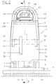
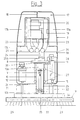
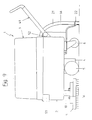
- the scrubber drier shown in the drawing has a housing 1 consisting of a lower part 2 and a top part 3 that can be opened
- Lower part 2 is a self-supporting, open at the top and formed essentially closed tub below and is therefore also referred to as tub 2 in the following.
- the tub 2 and the upper part 3 have one essentially rectangular plan on how it looks from Figure 4 can be seen.
- the vertical side walls 2a and 2b of the tub should cover at least a third extend the total height of the housing 1, on the one hand, to in the tub the essential components of the machine sheltered and on the other hand to to give the tub adequate stability, so that the tub can also be used without an additional one Frame construction forms a stable lower part.
- the height of the tub 2 is, however, essentially according to the height of the components to be accommodated, which are described in more detail below.
- the Drive 4 which drives the main wheels 5, screwed and protected from contamination by a hood. Furthermore, the castors 6 are on the floor 2c appropriate.
- the tub 2 suitably consists of sheet metal, in particular made of stainless steel.
- the upper part 3 After opening of the upper part 3 are, as shown in Figures 4 and 6 is, all of the aforementioned parts for maintenance purposes and, if necessary, for repair or replacement easily accessible. However, if the top is 3, 1-5, folded down, then that covers Upper part 3 the upwardly open tub 2 completely from, so that the components housed in the tub 2 from pollution and also from splash water are protected. In this context, it is advisable if the lower edge 3d of the upper part 3 the includes the upper edge 2d of the tub 2 from the outside as it is shown in Figure 3.
- the tub 2 can also be useful with a transverse wall 16 may be provided which the battery compartment of the separates the remaining interior of the tub and also also serves to stiffen the tub 2.
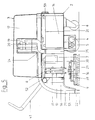
- the upper part 3 is useful as a self-supporting Tank 17 formed.
- the tank 17 has one Fresh water chamber 17a and a dirty water chamber 17b on either by a rigid partition 18 or by a movable (not shown) Membrane are separated from each other.
- the upper part 3 made of glass fiber reinforced plastic, especially glass fiber reinforced polyester.
- the upper part 3 has a large, in the drawings lid not shown.
- a central cavity 19 of the upper part 3 Expediently housed the suction pump (suction turbine) 20.
- the cavity 19 is on all sides of tank sections 17a, 17b surrounded entirely or partially with water are filled.
- the suction pump 20 is connected via a suction hose 21 a strip-shaped suction nozzle 22 of a known type connected.
- the suction hose 22 and others for cooling purposes the suction pump 20 serving ventilation hoses 23 are expedient on the underside of the tank bottom 17c led along.
- the ventilation hoses 23 are, however only shown in Figure 3.
- An exhaust pipe 24 leads from the suction pump 20 below.
- the upper part 3 When the upper part 3 is closed, it is aligned with the upper end 25a one arranged in the tub 2 Exhaust pipe 22, the lower end of the bath 2c the tub 2 opens into the open.
- the connection between the exhaust pipes 24, 25 are automatically sealed, when the upper part 3 is closed.
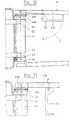
- a vertically displaceable support column 10 As a carrier for the brush unit 9 is tick a vertically displaceable support column 10 is provided.
- This support column 10 has, as can be seen from Figure 7 is a square or possibly also rectangular cross section. It stretches through a recess 26 in the bottom 2c of the tub down. However, the greater part of the support column 10 is inside the tub 2 arranged, as well as their leadership, the can be formed by several guide rollers 27.
- the guide rollers 27 are of course in corresponding Mounts, not shown, with are connected to the bottom 2c of the tub. Between the recess 26 and the support column 10 can be one seal, not shown, may be arranged.
- a support plate 30 connected, on the one hand that as a belt drive trained brush gear 8 and on the other hand the brush drive motor 7 carries.
- the latter and that Brush gear 8 are together with the whole Support column 10 can be raised and lowered.
- Inside the support column 10 is the drive shaft driven by the brush gear 8 31 stored.
- the one Half 32 of a dog clutch or the like arranged, the other half 33 with one in the brush housing 34 mounted output shaft 35 can be plugged together. of the output shaft 35 are those in the brush housing 34 housed disc brushes 29 over a not Distribution gear shown in a known manner driven.
- the axis A serves Connecting bolt 39 as a pendulum axis for the brush housing 34. Thanks to this swinging suspension of the brush housing 34, the two plate brushes 29 better adapt to the floor geometry.
- a Guide handle 41 is provided, which is useful as a is essentially U-shaped bracket.
- the closed ends 41a removed from the machine this bracket is angled upwards.
- This part 41a which is angled upwards expediently encloses, as can be seen from FIG. 2, an operating console 42, which the essential controls 43 and Display elements 44 has.
- the bracket 41 is on this way not only ergonomically shaped, but the controls 43 are also easily accessible. without having to let go of the bracket part 41a.
- the control panel 42 is expedient on a cross strut 45 of the bracket 41 attached.
- Control panel 42 with all essential operating and Display elements 43, 44 on bracket 41 is also essential if the scrubber drier to be converted so that the brush unit 9 is not, as shown in Figures 1-6, at the back the machine but should be arranged in front, like it is shown in Figure 9. This will be discussed below described in more detail.
- the U-shaped bracket 41 provided as a guide handle has two legs 41b directed towards the machine. These two legs 41b are on the bearing pieces 46 around a horizontal and transverse to the machine longitudinal direction L-L running axis B pivoted and lockable.
- the bracket 41 or its pivot axis B is on one of the two narrow sides of the machine is arranged, the bearing pieces 46 by means of screws 47 on one the narrow sides 2a of the tub 2 can be attached, as shown in Figure 10.
- the Bracket 41 By pivoting the bracket 41 about the axis B, the Bracket 41 can not only be adjusted in height but the distance of the bracket part 41a can also be opposite the narrow side of the machine. To this Way, the bracket 41 can easily be ergonomically correct Work position.
- To determine the Strap 41 opposite the one bearing piece 46 is on this one half 48a of a Hirth toothing attached.
- the other half 48b is attached to one leg 41b.
- the locking lever 50 provided with a cam 49 holds the two halves 48a, 48b of the Hirth serration normally engaged, causing the bracket 41 in the set height position is held. To change this height position the locking lever 50 in Pivoted towards C.
- the spring force of the bracket 41 forces the two halves 48a, 48b apart, so that the bracket 41 then swings up or down leaves.
- the new locking takes place in reverse Way, by the locking lever 50 against the Arrow direction C is moved.
- the two bearing pieces 46 are used advantageously also at the same time for mounting the pivot axis of the Upper part 3, which coincides with the axis B in this case.
- a bearing bush 51 rotatably supported on the two bearing pieces 46.
- the two swivel arms 52 are on the one hand with this bearing bush 51 and on the other hand firmly connected to the upper part 3.
- the upper part 3 around the Axis B, which is arranged on a narrow side 2a of the tub 2 is to be folded up as it is in Figure 6 is shown.
- the contained in the tub 2 Components are then easily accessible.
- a relief spring 55 is provided, which in the present Case is designed as a leg spring. expedient are such relief springs 55 on the two long sides 2b of the tub 2 or the upper part 3 is provided.
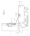
- the exhaust pipe 24 must be brought into a different position with respect to the upper part 3, so that it then aligns again with the exhaust pipe 25 in the tub 2. It may also be necessary to replace the drag arm 53 by a slightly differently shaped drag arm 53 '.
- the brush unit 9 is now arranged at the front end of the machine, ie in front of the wheels 5.
- the suction pump 20 is arranged in the upper part and that the upper part 3 is turned together with the bracket 41. It can then namely the suction hose 21 and further hose connections lead connected to the suction pump 20 and the tank 17.
- the suction hose 21 is also on the guide handle or bracket 41 assigned narrow side 3a of the upper part 3 in this inserted and along the bottom of the tank bottom 17c led to the suction pump 20.
- the linear motor 54, the with a cable 56 to raise and lower the Suction nozzle 22 is used on the underside of the tank bottom 17c arranged, as can be seen from Figure 8.
- the bracket 41, the upper part 3, the pivot bearing and the suction nozzle 22 together with the suction hose 21 and lifting device for the tow arm 53 into a convertible unit are summarized.
Landscapes
- Cleaning In General (AREA)
- Separation Of Particles Using Liquids (AREA)
Description
Die Erfindung betrifft eine Bodenreinigungsmaschine, insbesondere eine Scheuersaugmaschine, mit einem Gehäuse, bestehend aus einem Unterteil und einem demgegenüber aufklappbaren, haubenartigen Oberteil, mit mehreren an der Unterseite des Unterteils angebrachten Rädern, mit einer am Unterteil mittels eines höhenbeweglichen Trägers gelagerten Bürsteneinheit, die von einem am Unterteil angeordneten Bürstenantriebsmotor über ein Bürstengetriebe antreibbar ist, mit einer leistenförmigen Saugdüse, die an eine Saugpumpe angeschlossen ist, mit einem zwei Kammern aufweisenden Tank und mit mehreren Batterien und/oder sonstigen Stromversorgungseinheiten.The invention relates to a floor cleaning machine, especially a scrubber drier, with a housing, consisting of a lower part and an opposite hinged, hood-like top, with several wheels attached to the underside of the lower part, with one on the lower part by means of a height-adjustable Carrier-mounted brush unit by a Lower part arranged brush drive motor over a Brush gear is drivable, with a strip-shaped Suction nozzle connected to a suction pump, with a two-chamber tank and with several Batteries and / or other power supply units.
Bei derartigen Scheuersaugmaschinen (vgl. US-A-3,277,511) besteht das Unterteil in der Regel aus einer aus mehreren Stahlprofilen zusammengeschweißten Rahmenkonstruktion, die außen eine Verkleidung aus Blech oder Kunststoff trägt. Im unteren Teil dieser Rahmenkonstruktion sind der Bürstenantriebsmotor, die Saugpumpe, der Träger für die Bürsteneinheit usw. angeordnet. Diese Teile sind zwar durch seitliche Verkleidungen weitgehend unsichtbar, jedoch starker Verschmutzung ausgesetzt, da die Rahmenkonstruktion nach unten offen ist. Vorgenannte Teile sind zu Reinigungs-, Wartungs- und Reparaturzwecken schwer zugänglich. Das Bürstengetriebe befindet sich direkt oberhalb der Borsteneinheit. Um es vor Staub und Wasser zu schützen muß es entsprechend gekapselt sein. Das gleiche gilt für den Bürstenantriebsmotor, der bei vielen anderen Konstruktionen direkt auf der Bürsteneinheit montiert ist. Da mit der Bürsteneinheit zumindest das Bürstengetriebe, vielfach aber auch der Bürstenantriebsmotor, verbunden ist, kann man die Bürsteneinheit nicht einfach gegen eine andere Bürsteneinheit, z.B. mit einer anderen Arbeitsbreite, oder gegen eine neue austauschen. Die für cas Unterteil vorgesehene Rahmenkonstruktion einschließlich Verkleidung ist verhältnismäßig teuer in der Herstellung und auch schwer. Bei der bekannten Maschine ist ferner der Tank im Unterteil angeordnet. Die Batterien sind auf der Oberseite des Unterteils abgestellt. Die Reinigung des Tanks ist daher sehr erschwert und erst nach Entfernung der Batterien möglich. Außerdem hat ein relativ tiefliegender Tank den Nachteil, daß der Tankinhalt nicht ohne weiteres in einen Ausguß entleert werden kann, der mit Abstand vom Boden angeordnet ist. Es ist daher meist noch eine zusätzliche Entleerungspumpe erforderlich.In such scrubber driers (cf. US-A-3,277,511) the lower part usually consists of one Steel profiles welded together frame construction outside is covered with sheet metal or plastic. At the bottom Part of this frame construction are the brush drive motor, the suction pump, the support for the brush unit etc. arranged. Although these parts are by side Fairings largely invisible, but heavily soiled exposed because the frame construction after is open at the bottom. The above parts are for cleaning, Maintenance and repair purposes difficult to access. The Brush gear is located directly above the bristle unit. To protect it from dust and water it has to be encapsulated accordingly. The same applies to the Brush drive motor that is used in many other designs is mounted directly on the brush unit. There with the brush unit at least the brush gear, but often also the brush drive motor the brush unit cannot simply be countered another brush unit, e.g. with a different working width, or exchange for a new one. The for cas Lower part provided frame construction including Fairing is relatively expensive to manufacture and also difficult. In the known machine is also the tank arranged in the lower part. The batteries are on the top of the lower part. The cleaning of the tank is therefore very difficult and only after removal of batteries possible. It also has a relative deep tank the disadvantage that the tank capacity cannot easily be emptied into a sink, which is spaced from the floor. It is therefore usually an additional drain pump is required.
Bei den bisher bekannten, mit einer oder mehreren Tellerbürsten arbeitenden Scheuersaugmaschinen ist entweder die Bürsteneinheit, in Fahrtrichtung gesehen, vor den Rädern oder hinter den Rädern angeordnet. Beide Systeme haben gewisse Vorteile aber auch Nachteile. Allen bekannten Scheuersaugmaschinen ist jedoch gemeinsam, daß die Anordnung der Bürsteneinheit gegenüber den Rädern nachträglich nicht verändert werden kann, d.h. eine Scheuersaugmaschine mit vorne angeordneter Bürsteneinheit kann nicht in eine solche mit hinten angeordneter Bürsteneinheit in einfacher Weise umgebaut werden.In the previously known, with one or more plate brushes is working scrubber drier either the brush unit, seen in the direction of travel, in front of the Wheels or arranged behind the wheels. Both systems have certain advantages but also disadvantages. All known However, scrubber driers have in common that the arrangement of the brush unit opposite the wheels cannot be changed subsequently, i.e. a Scrubber drier with brush unit at the front can not be arranged in such a way with rear Brush unit can be converted in a simple manner.
Der Erfindung liegt die Aufgabe zugrunde, eine Bodenreinigungsmaschine, insbesondere Scheuersaugmaschine, der eingangs erwähnten Art zu schaffen, die einfacher im Aufbau ist, bei der die meisten Komponenten optimal geschützt untergebracht und trotzdem im Bedarfsfalle leicht zugänglich sind und die außerdem leicht zu reinigen ist. The invention has for its object a floor cleaning machine, especially scrubber drier, of the kind mentioned in the introduction to create the easier is under construction, with most components optimal sheltered and still in case of need are easily accessible and also easy to access is clean.
Dies wird nach der Erfindung dadurch erreicht, daß das Unterteil als eine selbsttragende, oben offene und unten im wesentlichen geschlossene Wanne ausgebildet ist, deren vertikale Seitenwände sich mindestens über ein Drittel der Gesamthöhe des Gehäuses erstrecken und in welcher zumindest der Bürstenantriebsmotor, das Bürstengetriebe, ein Hubmotor für den Träger, wesentliche Teile desselben und die Batterien angeordnet sind, und daß das Oberteil den Tank enthält. Der Boden der Wanne weist eine Ausnehmung für die Passage des höhenbeweglichen Trägers auf.This is achieved according to the invention in that the Lower part as a self-supporting, open at the top and bottom essentially closed trough is formed, whose vertical side walls are at least over one Third of the total height of the case and in which at least the brush drive motor, the brush gear, a lifting motor for the carrier, essential Parts of the same and the batteries are arranged, and that the top part contains the tank. The bottom of the tub is facing a recess for the passage of the vertically movable support.
Bei der neuen Maschine kommt der selbsttragenden Wanne wesentliche Bedeutung zu. Sie ersetzt nämlich die bisherige Rahmenkonstruktion und deren Verkleidung. Die Wanne ist kostengünstig herstellbar, sie bildet eine Tragkonstruktion und auch eine Verkleidung in einem. Gleichzeitig bildet sie auch einen wirksamen Schutz gegen Verschmutzung der wichtigsten Maschinenkomponenten, da sie nicht nur zur Seite hin sondern auch nach unten im wesentlichen geschlossen ist. Die wichtigsten Maschinenkomponenten sind optimal geschützt im Innern der Wanne untergebracht. Dies gilt nicht nur für den Bürstenmotor, das Bürstengetriebe, den Hubmotor und wesentliche Teile des Trägers, sondern auch für die Batterien und insbesondere auch die elektronische Steuerung der Maschine, die in vorteilhafter Weise in der Wanne montiert sein kann. Nach dem Aufklappen des den Tank enthaltenden Oberteils sind sämtliche, in der Wanne enthaltenen Komponenten zu Service- und Reparaturzwecken frei und bequem zugänglich. Sie können im Bedarfsfalle von ihren Halterungen in der Wanne leicht gelöst und nach oben herausgenommen werden. An der Unterseite der Wanne sind unmittelbar die Räder montiert. Da die meisten Teile des Bürstenantriebes, nämlich der Bürstenmotor, das Bürstengetriebe und auch der Hubmotor sowie wesentliche Teile des Trägers im Innern der Wanne vor Verschmutzung geschützt angeordnet sind, ist die Reinigung der Maschine sehr einfach. Es brauchen nämlich praktisch nur die Bürsteneinheit und die Räder gereinigt werden. Die glatten Außenwände der Wanne und des Oberteils lassen sich ebenfalls leicht und schnell reinigen. Da bei der neuen Maschine wesentliche Teile des Bürstenantriebes, insbesondere der Bürstenantriebsmotor und das Bürstengetriebe, in der Wanne untergebracht sind, hat die neue Maschine auch den Vorteil, daß die motorlosen Bürsteneinheiten im Bedarfsfalle leicht gewechselt werden können. Bei Beschädigung einer solchen motorlosen Bürsteneinheit kann diese leicht gegen eine neue oder instandgesetzte oder eine solche mit einer anderen Arbeitsbreite ausgetauscht werden. Die Anordnung des Tanks im Oberteil hat den Vorteil, daß der Tank relativ hoch liegt und deshalb sein Inhalt problemlos ohne Entleerungspumpe in einen Ausguß entleert werden kann.The self-supporting tub comes with the new machine essential importance. It replaces the previous one Frame construction and its cladding. The Trough is inexpensive to manufacture, it forms one Supporting structure and also a cladding in one. At the same time, it also provides effective protection against contamination of the most important machine components, since they not only move to the side but also to the side is essentially closed at the bottom. The most important Machine components are optimally protected inside the tub. This does not only apply to the Brush motor, the brush gear, the lifting motor and essential parts of the carrier, but also for the Batteries and especially electronic ones Control of the machine, which advantageously in the tub can be installed. After opening the the upper part containing the tank are all in the Tub contained components for service and repair purposes freely and easily accessible. You can if necessary from their brackets in the tub easily loosened and removed upwards. At the The wheels are mounted directly on the underside of the tub. Since most parts of the brush drive, namely the brush motor, the brush gear and also the lifting motor and essential parts of the carrier in Arranged inside the tub protected from contamination cleaning the machine is very easy. It practically only need the brush unit and the wheels are cleaned. The smooth outer walls of the The tub and the top are also easy to use and clean quickly. Because essential with the new machine Parts of the brush drive, especially the Brush drive motor and the brush gear in which Tub, the new machine also has the advantage that the motorless brush units in If necessary, can be easily changed. at Damage to such a motorless brush unit can easily be used against a new or repaired one or one with a different working width be replaced. The arrangement of the tank in the upper part has the advantage that the tank is relative is high and therefore its content without problems Drain pump can be drained into a spout.
Besonders vorteilhaft ist es, wenn das Oberteil als selbsttragender Tank ausgebildet ist. Zu diesem Zweck kann das Oberteil zweckmäßig aus glasfaserverstärktem Kunststoff bestehen. Durch die Ausgestaltung des Oberteils als selbsttragenden Tank wird die Konstruktion vereinfacht und damit werden auch die Herstellungskosten gesenkt und das Gewicht verringert.It when the upper part as self-supporting tank is formed. To this end the upper part can be made of glass fiber reinforced Plastic. Due to the design of the upper part The construction becomes a self-supporting tank simplified and thus also the manufacturing costs lowered and weight decreased.
Eine weitere, besonders vorteilhafte Ausgestaltung besteht darin, daß an dem Führungsgriff ein Bedienungspult mit den wesentlichen Bedienungs- und Anzeigeelementen angeordnet ist, und daß der Führungsgriff wahlweise mit der einen oder der anderen Stirnseite der Maschine, insbesondere der Wanne, verbindbar ist. Another, particularly advantageous embodiment is that a control panel on the guide handle with the essential operating and display elements is arranged, and that the guide handle is optional with one or the other end of the Machine, especially the tub, is connectable.
Hierdurch ist es möglich, mit einem verhältnismäßig geringen Montageaufwand eine Maschine mit vorne liegender Bürsteneinheit in eine solche mit hinten liegender Bürsteneinheit umzuwandeln. Insbesondere kann der Maschinenhersteller beide Maschinentypen anbieten ohne daß sich hierdurch die Herstellungs- oder Lagerhaltungskosten erhöhen.This makes it possible to be proportionate low installation effort a machine with front Brush unit in one with a rear Convert brush unit. In particular, the machine manufacturer offer both types of machines without the manufacturing or storage costs increase.
Weitere vorteilhafte Ausgestaltungen sind in den übrigen Unteransprüchen gekennzeichnet.Further advantageous configurations are in the rest Subclaims marked.
Die Erfindung ist in folgendem, anhand eines in der Zeichnung dargestellten Ausführungsbeispieles näher erläutert. Es zeigen:
Figur 1- eine Seitenansicht der Maschine mit hinten angeordneter Bürsteneinheit,
Figur 2- eine Stirnansicht der Maschine in Richtung II
der
Figur 1, Figur 3- einen Querschnitt nach der Linie III-III der
Figur 1, Figur 4- einen Horizontalschnitt nach der Linie IV-IV
der
Figur 1, Figur 5- einen Längsschnitt der Maschine nach der Linie
V-V der
Figur 2, jedoch mit demontierter Bürsteneinheit, Figur 6- eine Seitenansicht der Maschine mit aufgeklapotem Oberteil,
Figur 7- einen Teilquerschnitt nach der Linie VII-VII
der
Figur 1, Figur 8- eine Seitenansicht der Maschine in einer Umbauphase,
Figur 9- eine Seitenansicht der Maschine nach erfolgtem Umbau, mit vorne angeordneter Bürsteneinheit.
Figur 10- eine Draufsicht auf die Lagerung des Führungsgriffes und des Oberteils bei verriegeltem Führungsgriff,
Figur 11- eine Teildraufsicht mit gelöstem Führungsgriff.
- Figure 1
- a side view of the machine with the rear brush unit,
- Figure 2
- 3 shows an end view of the machine in the direction II of FIG. 1,
- Figure 3
- 2 shows a cross section along the line III-III of FIG. 1,
- Figure 4
- 2 shows a horizontal section along the line IV-IV in FIG. 1,
- Figure 5
- 3 shows a longitudinal section of the machine along the line VV in FIG. 2, but with the brush unit removed,
- Figure 6
- a side view of the machine with the upper part opened,
- Figure 7
- 2 shows a partial cross section along the line VII-VII of FIG. 1,
- Figure 8
- a side view of the machine in a conversion phase,
- Figure 9
- a side view of the machine after conversion, with the brush unit arranged at the front.
- Figure 10
- a plan view of the storage of the guide handle and the upper part with the guide handle locked,
- Figure 11
- a partial plan view with the guide handle released.
Die in der Zeichnung dargestellte Scheuersaugmaschine
weist ein Gehäuse 1 auf, bestehend aus einem Unterteil 2
und einem demgegenüber aufklappbaren Oberteil 3. Das
Unterteil 2 ist als eine selbsttragende, oben offene
und unten im wesentlichen geschlossene Wanne ausgebildet
und wird daher in folgendem auch als Wanne 2 bezeichnet.
Die Wanne 2 und das Oberteil 3 weisen einen
im wesentlichen rechteckigen Grundriß auf, wie es aus
Figur 4 erkennbar ist. Die vertikalen Seitenwände 2a
und 2b der Wanne sollen sich über mindestens ein Drittel
der Gesamthöhe des Gehäuses 1 erstrecken, einerseits, um
in der Wanne die wesentlichen Komponenten der Maschine
geschützt unterbringen zu können und andererseits, um
der Wanne eine entsprechende Stabilität zu verleihen,
damit die Wanne gleichzeitig auch ohne eine zusätzliche
Rahmenkonstruktion ein stabiles Unterteil bildet.
Die Höhe der Wanne 2 richtet sich jedoch im wesentlichen
nach der Höhe der darin unterzubringenden Komponenten,
die nachstehend noch näher beschrieben werden.The scrubber drier shown in the drawing
has a
An der Unterseite des Bodens 2c der Wanne 2 ist der
Fahrantrieb 4, der die Haupträder 5 antreibt, angeschraubt
und durch eine Haube vor Verschmutzung geschützt.
Ferner sind am Boden 2c die Lenkrollen 6
angebracht.At the bottom of the bottom 2c of the
Die Wanne 2 besteht zweckmäßig aus Blech, insbesondere
aus rostfreiem Stahl. Im Innern der Wanne 2 sind der
Bürstenantriebsmotor 7, das Bürstengetriebe 8, eine
als Träger für die Bürsteneinheit 9 dienende Tragsäule
10, ein Hubmotor 11 für die Tragsäule, eine Frischwasserpumpe
12, gegebenenfalls eine Recyclingpumpe 13,
die Batterien 14 und vor allem auch die Steuerelektronik
in sauberer und geschützter Umgebung sowie wartungsfreundlich
untergebracht. Nach dem Aufklappen
des Oberteils 3 sind, wie es in Figur 4 und 6 dargestellt
ist, alle vorgenannten Teile zu Wartungszwecken
und falls erforderlich, zur Reparatur bzw. zum Austausch
leicht zugänglich. Ist jedoch das Oberteil 3,
gemäß Figur 1 - 5, heruntergeklappt, dann deckt das
Oberteil 3 die nach oben offene Wanne 2 vollständig
ab, so daß die in der Wanne 2 untergebrachten Komponenten
vor Verschmutzung und auch vor Spritzwasser
geschützt sind. In diesem Zusammenhang ist es zweckmäßig,
wenn der untere Rand 3d des Oberteils 3 den
oberen Rand 2d der Wanne 2 von außen umfaßt, wie es
in Figur 3 dargestellt ist.The
Die Wanne 2 kann zweckmäßig auch mit einer Querwand
16 versehen sein, welche das Batterieabteil von dem
übrigen Innenraum der Wanne abtrennt und außerdem
auch zur Versteifung der Wanne 2 dient.The
Das Oberteil 3 ist zweckmäßig als selbsttragender
Tank 17 ausgebildet. Der Tank 17 weist dabei eine
Frischwasserkammer 17a und eine Schmutzwasserkammer
17b auf, die entweder durch eine starre Trennwand 18
oder durch eine bewegliche (nicht dargestellte)
Membrane voneinander getrennt sind. Zweckmäßig besteht
das Oberteil 3 aus glasfaserverstärktem Kunststoff,
insbesondere glasfaserverstärktem Polyester.
Das Oberteil 3 weist oben einen großflächigen, in
den Zeichnungen nicht dargestellten Deckel auf. The
Dieser ermöglicht eine gute Zugänglichkeit des Tanks 17
zum Füllen mit Wasser und auch zur Tankreinigung.This enables the
In einem zentralen Hohlraum 19 des Oberteiles 3 ist
zweckmäßig die Saugpumpe (Saugturbine) 20 untergebracht.
Der Hohlraum 19 ist dabei allseitig von Tankabschnitten
17a, 17b umgeben, die ganz oder teilweise mit Wasser
gefüllt sind. Durch diese Maßnahmen und die Tatsache,
daß das Oberteil 3 aus glasfaserverstärktem Kunststoff
besteht, werden die Geräusche der Saugpumpe 20 stark
gedämpft.In a
Die Saugpumpe 20 ist über einen Saugschlauch 21 mit
einer leistenförmigen Saugdüse 22 bekannter Bauart
verbunden. Der Saugschlauch 22 und weitere zu Kühlzwecken
der Saugpumpe 20 dienende Belüftungsschläuche
23 sind zweckmäßig an der Unterseite des Tankbodens 17c
entlang geführt. Die Belüftungsschläuche 23 sind jedoch
nur in Figur 3 dargestellt.The
Von der Saugpumpe 20 führt ein Abluftrohr 24 nach
unten. Bei geschlossenem Oberteil 3 fluchtet dieses
mit dem oberen Ende 25a eines in der Wanne 2 angeordneten
Abluftrohres 22, dessen unteres Ende am Baden 2c
der Wanne 2 ins Freie mündet. Die Verbindung zwischen
den Abluftrohren 24, 25 ist automatisch abgedichtet,
wenn das Oberteil 3 geschlossen ist.An
Als Träger für die Bürsteneinheit 9 ist zueckmäßig
eine vertikal verschiebbare Tragsäule 10 vorgesehen.
Diese Tragsäule 10 weist, wie aus Figur 7 ersichtlich
ist, einen quadratischen oder gegebenenfalls auch
rechteckigen Querschnitt auf. Sie erstreckt sich
durch eine Ausnehmung 26 im Boden 2c der Wanne nach unten.
Der größere Teil der Tragsäule 10 ist jedoch im Inneren
der Wanne 2 angeordnet, ebenso wie ihre Führung, die
durch mehrere Führungsrollen 27 gebildet sein kann.
Die Führungsrollen 27 sind selbstverständlich in entsprechenden,
nicht dargestellten Halterungen, die mit
dem Boden 2c der Wanne verbunden sind, gelagert. Zwischen
der Ausnehmung 26 und der Tragsäule 10 kann noch eine
nicht dargestellte Dichtung angeordnet sein.As a carrier for the
Mit dem oberen Ende 10a der Tragsäule 10 ist ein Arm 28
verbunden, an welchem der Hubmotor 11 angreift. Mit dem
Hubmotor 11 kann die Tragsäule 10 nicht nur in vertikaler
Richtung V auf und ab bewegt werden, sondern durch
den Hubmotor 11 kann auch der Anpreßdruck der Tellerbürsten
29 oder von Padscheiben an den Boden reguliert
werden.With the upper end 10a of the
Mit dem oberen Ende 10a der Tragsäule 10 ist eine Tragplatte
30 verbunden, die einerseits das als Riementrieb
ausgebildete Bürstengetriebe 8 und andererseits auch
den Bürstenantriebsmotor 7 trägt. Letzterer und das
Bürstengetriebe 8 sind also zusammen mit der gesamten
Tragsäule 10 heb- und senkbar. Im Innern der Tragsäule 10
ist die vom Bürstengetriebe 8 angetriebene Antriebswelle
31 gelagert. Am unteren Ende derselben ist die eine
Hälfte 32 einer Klauenkupplung oder dgl. angeordnet,
deren andere Hälfte 33 mit einer im Bürstengehäuse 34
gelagerten Abtriebswelle 35 zusammensteckbar ist. von
der Abtriebswelle 35 werden die im Bürstengehäuse 34
untergebrachten Scheibenbürsten 29 über ein nicht
dargestelltes Verteilgetriebe in bekannter Weise
angetrieben. With the upper end 10a of the
Um das Bürstengehäuse 34 von der Tragsäule 10 leicht
lösen und wieder montieren zu können sind, wie es insbesondere
in Figur 7 dargestellt ist, an dem Bürstengehäuse
34 an zwei gegenüberliegenden Seiten der Tragsäule
10 zwei Traglaschen 36 befestigt, von denen jede
eine Querbohrung 37 aufweist. Am unteren Ende 10b der
Tragsäule sind ferner an den genannten gegenüberliegenden
Seiten zwei Querbohrungen 38 vorgesehen, die in
Verbindungsstellung von Tragsäule 10 und Bürstengehäuse
34 miteinander fluchten, wie es in Figur 7 gezeigt ist.
In diese Querbohrungen 37, 38 sind die Verbindungsbolzen
39 einsteckbar, die mittels der an den Laschen 36
schwenkbar angeordneten Riegel 40 verriegelbar sind.Around the
Zur Demontage einer Bürsteneinheit 9 von der Tragsäule
10 wird diese mittels des Hubmotors 11 nach unten gefahren,
bis sich die Tellerbürsten 29 am Boden abstützen.
Die Riegel 40 werden entriegelt und die Uerbindungsbolzen
39 können dann leicht aus den Querbohrungen
37, 38 herausgezogen werden. Die Tragsäule 10
kann dann um ein Stück nach oben gefahren werden und
man kann die gesamte Bürsteneinheit seitlich oder nach
vorne unter der Wanne 2 herausziehen. Es kann dann eine
andere Bürsteneinheit unter die Maschine eingeschoben
werden. In umgekehrter Weise wird dann die Tragsäule
10 abgesenkt und wieder zwischen die Laschen 36 der
neuen Bürsteneinheit gebracht. Sobald die Querbohrungen
38 der Tragsäule 10 mit den Querbohrungen 37 der
Lasche 36 fluchten, können die Verbindungsbolzen 39
in jeweils beide Querbohrungen 36, 37 eingeschoben und
mittels der Riegel 40 gesichert werden. Beim Absenken
der Tragsäule kommen automatisch auch die beiden
Hälften 32, 33 der Klauenkupplung wieder miteinander
in Eingriff, wodurch die Antriebsverbindung zwischen
Antriebswelle 31 und Abtriebswelle 35 hergestellt wird.
Auf diese Weise kann man sehr einfach eine Bürsteneinheit
mit einer Arbeitsbreite von beispielsweise 550 mm
gegen eine andere Bürsteneinheit mit einer Arbeitsbreite
von beispielsweise 700 mm auswechseln und umgekehrt.
Außerdem kann man dank der einfachen Montage- und Demontagemöglichkeit
auch die Bürsteneinheit zu Reinigungsund
Wartungszwecken leicht abnehmen und dann in bequemer
Arbeitshöhe auf einem Arbeitstisch säubern, warten oder
reparieren.For dismantling a
Wenn die Querbohrungen 37, 38, wie es bei dem gezeigten
Ausführungsbeispiel der Fall ist, in Maschinenlängsrichtung
L-L angeordnet werden, dann dient die Achse A der
Verbindungsbolzen 39 als Pendelachse für das Bürstengehäuse
34. Dank dieser pendelnden Aufhängung des Bürstengehäuses
34 können sich die beiden Tellerbürsten 29
besser der Bodengeometrie anpassen.If the transverse bores 37, 38, as shown in the
Embodiment is the case in the machine longitudinal direction
L-L are arranged, then the axis A serves
Connecting
Zur Führung und Bedienung der Maschine ist ferner ein
Führungsgriff 41 vorgesehen, der zweckmäßig als ein
im wesentlichen U-förmiger Bügel ausgebildet ist. Das
von der Maschine entfernte, geschlossene Ende 41a
dieses Bügels ist dabei nach oben abgewinkelt. Dieses
nach oben abgewinkelte Teil 41a umschließt zweckmäßig,
wie aus Figur 2 ersichtlich ist, ein Bedienungspult 42,
welches die wesentlichen Bedienungselemente 43 und
Anzeigeelemente 44 aufweist. Der Bügel 41 ist auf
diese Weise nicht nur ergonomisch geformt, sondern
die Bedienungselemente 43 sind auch leicht erreichbar.
ohne daß man hierzu das Bügelteil 41a loslassen müßte.
Das Bedienungspult 42 ist zweckmäßig an einer Querstrebe
45 des Bügels 41 befestigt. Die Anordnung des
Bedienungspultes 42 mit allen wesentlichen Bedienungsund
Anzeigeelementen 43, 44 am Bügel 41 ist aber auch
von wesentlicher Bedeutung, wenn die Scheuersaugmaschine
so umgebaut werden soll, daß die Bürsteneinheit 9 nicht,
wie es in den Figuren 1 - 6 dargestellt ist, hinten an
der Maschine sondern vorne angeordnet sein soll, wie
es in Figur 9 gezeigt ist. Dies wird nachstehend noch
näher beschrieben.To operate and operate the machine is also a
Der als Führungsgriff vorgesehene U-förmige Bügel 41
weist zwei zur Maschine gerichtete Schenkel 41b auf.
Diese beiden Schenkel 41b sind an den Lagerstücken 46
um eine horizontale und quer zur Maschinenlängsrichtung
L-L verlaufende Achse B schwenkbar und feststellbar gelagert.
Der Bügel 41 bzw. dessen Schwenkachse B ist an
einer der beiden Schmalseiten der Maschine angeordnet,
wobei die Lagerstücke 46 mittels Schrauben 47 an einer
der Schmalseiten 2a der Wanne 2 befestigt werden können,
wie es in Figur 10 gezeigt ist.The
Durch Verschwenken des Bügels 41 um die Achse B kann der
Bügel 41 nicht nur in der Höhe verstellt werden sondern
es kann auch der Abstand des Bügelteiles 41a gegenüber
der Schmalseite der Maschine verändert werden. Auf diese
Weise kann der Bügel 41 leicht in die ergonomisch richtige
Arbeitsposition gebracht werden. Zur Feststellung des
Bügels 41 gegenüber dem einen Lagerstück 46 ist an diesem
die eine Hälfte 48a einer Hirth-Verzahnung befestigt. Die
andere Hälfte 48b ist an dem einen Schenkel 41b befestigt.
Der mit einem Nocken 49 versehene Verriegelungshebel 50
hält die beiden Hälften 48a, 48b der Hirth-Verzahnung
normalerweise in Eingriff, wodurch der Bügel 41 in der
eingestellten Höhenstellung gehalten wird. Zum Verändern
dieser Höhenstellung wird der Verriegelungshebel 50 in
Richtung C verschwenkt. Die Federkraft des Bügels 41
zwingt die beiden Hälften 48a, 48b auseinander, so daß sich dann der Bügel 41 nach oben oder unten schwenken
läßt. Die erneute Verriegelung erfolgt in umgekehrter
Weise, indem der Verriegelungshebel 50 entgegen der
Pfeilrichtung C bewegt wird.By pivoting the
Die beiden Lagerstücke 46 dienen in vorteilhafter Weise
auch gleichzeitig zur Lagerung der Schwenkachse des
Oberteiles 3, die in diesem Fall mit der Achse B zusammenfällt.
Zu diesem Zweck ist eine Lagerbüchse 51
drehbar an den beiden Lagerstücken 46 gelagert. Die
beiden Schwenkarme 52 sind einerseits mit dieser Lagerbüchse
51 und andererseits mit dem Oberteil 3 fest verbunden.
Auf diese Weise kann das Oberteil 3 um die
Achse B, die an einer Schmalseite 2a der Wanne 2 angeordnet
ist, nach oben geklappt werden, wie es in
Figur 6 dargestellt ist. Die in der Wanne 2 enthaltenen
Komponenten sind dann leicht zugänglich.The two bearing
Damit sich das Oberteil 3 trotz seines Gewichtes leicht
aufklappen läßt, ist zwischen beiden Teilen mindestens
eine Entlastungsfeder 55 vorgesehen, die im vorliegenden
Fall als Schenkelfeder ausgebildet ist. Zweckmäßig
sind derartige Entlastungsfedern 55 an den beiden Längsseiten
2b der Wanne 2 bzw. des Oberteiles 3 vorgesehen.So that the
Anhand der Figuren 1, 8 und 9 soll nun beschrieben werden,
wie sich die Maschine mit hinten angeordneter Bürsteneinheit
9 gemäß Figur 1 in eine Maschine mit vorne angeordneter
Bürsteneinheit 9 gemäß Figur 9 in einfacher Weise
umbauen läßt. Hierzu wird zunächst der Schlepparm 53,
welcher die Saugdüse 22 trägt, von der Wanne 2 gelöst.
Es werden dann auch die Schrauben 47 der Lagerstücke 46
entfernt. Man kann nunmehr die gesamte, aus Oberteil 3,
Bügel 41, Saugschlauch 21 und Saugdüse 22 bestehende
Einheit von der Wanne 2 abnebe und um 180° drehen,
wie es mit strichpunktierten Linien in Figur 8 dargestellt
ist. Vor dem Abnehmen dieser Einheit müssen
noch einige elektrische Kabel, die vom Bedienungspult
durch einen der hohlen Schenkel 41b des Bügels 41 und
durch einen Kanal in dem einen Lagerstück 46 in das
Innere der Wanne geführt sind und über Steckerverbindungen
mit der Steuereinheit 15 verbunden sind, gelöst
werden. Die Lagerstücke 46 werden dann an der gegenüberliegenden
Schmalseite 2a der Wanne angesetzt, wo
bereits entsprechende Bohrungen für die Schrauben
47 und auch für die elektrischen Kabel vorbereitet
sind, die zuvor zur Befestigung eines Stoßfängers 59
dienten, der nunmehr an der Stirnwand angebracht wird,
an welcher vorher die Lagerstücke 46 montiert waren.
Nach dem Befestigen der Lagerstücke an der
gegenüberliegenden Stirnwand 2a ist es nur noch erforderlich,
die elektrischen Leitungen wieder mit
der Steuereinheit 15 zu verbinden. Ferner muß noch
das Abluftrohr 24 gegenüber dem Oberteil 3 in eine
andere Position gebracht werden, damit es anschliessend
wieder mit dem Abluftrohr 25 in der Wanne 2
fluchtet. Gegebenenfalls ist es auch noch erforderlich,
den Schlepparm 53 durch einen etwas anders
geformten Schlepparm 53' zu ersetzen. Nach dem
Umbau der Maschine ist nunmehr die Bürsteneinheit 9
am vorderen Ende der Maschine angeordnet, d.h. vor
den Rädern 5.1, 8 and 9, it will now be described how the machine with the
The
Für das Umrüsten der Maschine von hinten angeordneter
Bürsteneinheit auf vorne angeordnete Bürsteneinheit
ist es u.a. auch wesentlich, daß die Saugpumpe
20 im Oberteil angeordnet ist und daß das Oberteil 3
zusammen mit dem Bügel 41 gewendet wird. Es können
dann nämlich der Saugschlauch 21 und weitere Schlauchverbindungen
mit der Saugpumpe 20 sowie dem Tank 17 verbunden bleiden. Zu diesem Zweck ist auch der Saugschlauch 21 an der dem Führungsgriff bzw. Bügel 41
zugeordneten Schmalseite 3a des Oberteils 3 in dieses
eingeführt und entlang der Unterseite des Tankbodens 17c
zu der Saugpumpe 20 geführt.For rearranging the machine from the rear
Brush unit on the front brush unit
is it u.a. also essential that the
Aus dem gleichen Grund ist auch der Linearmotor 54,
der mit einem Seilzug 56 zum Anheben und Absenken der
Saugdüse 22 dient, an der Unterseite des Tankbodens 17c
angeordnet, wie es aus Figur 8 ersichtlich ist. Für das
Umrüsten der Maschine von hinten auf vorne angeordnete
Bürsteneinheit 9 und umgekehrt, ist es also wesentlich,
daß der Bügel 41, das Oberteil 3, dessen Schwenklagerung
und die Saugdüse 22 samt Saugschlauch 21 und Hebevorrichtung
für den Schlepparm 53 zu einer umsetzbaren Einheit
zusammengefaßt sind.For the same reason, the
Es gibt auch Bodenreinigungsmaschinen, die über ein
Stromkabel vom normalen Stromnetz aus betrieben werden.
Da bei solchen Maschinen keine Batterien erforderlich
sind, werden anstelle derselben ein Spannungswandler
und sonstige zur Stromversorgung dienende Einheiten
in der Wanne 2 untergebracht.There are also floor cleaning machines that have a
Power cables are operated from the normal power network.
Since no batteries are required in such machines
are a voltage converter instead of the same
and other power supply units
housed in the
Claims (26)
- Floor cleaning machine, in particular vacuum scrubbing machine, with a housing (1), consisting of a lower part (2) and a hood-like upper part (3) which is pivotable in relation to it, with a plurality of wheels (5) mounted on the underside of the lower part (2), with a brush unit (9) which is mounted on the lower part (2) by means of a height-adjustable carrier (10) and driveable by a brush-driving motor (7) arranged on the lower part (2) through a brush gear unit (8), with a strip-shaped suction nozzle (22) which is connected to a suction pump (20), with a tank exhibiting two chambers, and with a plurality of batteries (14) and/or other power supply units, characterised in that the lower part (2) is embodied as a self-supporting tub (2) which is open at the top and essentially closed at the bottom and whose vertical side walls (2a, 2b) extend at least over a third of the overall height of the housing (1), the bottom (2c) of the tub (2) exhibiting an opening (26) for passage of the height-adjustable carrier (10), and which tub (2) accommodates at least the brush driving motor (7), the brush gear unit (8), a lifting motor (11) for the carrier (10), essential parts thereof and the batteries (14) and/or other power supply units, and in that the upper part (3) contains the tank (17).
- Machine according to claim 1, characterised in that the tub (2) is made of sheet metal, in particular of stainless steel.
- Machine according to claim 1, characterised in that the upper part (3) is designed as a self-supporting tank.
- Machine according to claim 1 or 3, characterised in that the upper part (3) is made of glass fibre-reinforced plastic.
- Machine according to claim 1, 3 or 4, characterised in that the suction pump (20) is arranged in a central cavity (19) of the upper part (3).
- Machine according to claim 5, characterised in that the cavity (19) is surrounded by tank sections (17a, 17b).
- Machine according to one of claims 1 to 6, characterised in that the lower edge (3d) of the upper part (3) fits externally over the upper edge (2d) of the tub (2).
- Machine according to one of claims 1 to 7, characterised in that the tub (2) and the upper part (3) exhibit an essentially rectangular ground plan and in that the upper part (3) is pivotable in relation to the tub (2) about a horizontal pivot axis (B) arranged on one narrow side (2a) of the tub (2).
- Machine according to claim 8, characterised in that the pivot axis (B) is arranged on the same narrow side (2a) as a guiding handle (41).
- Machine according to claim 1, characterised in that the carrier for the brush unit (9) takes the form of a vertically displaceable carrying column (10) which extends through the opening (26) in the bottom (2c) of the tub (2).
- Machine according to claim 10, characterised in that a guiding device (27) for the carrying column (10) is arranged and supported in the interior of the tub (2).
- Machine according to claim 10 or 11, characterised in that the brush gear unit (8) and the brush driving motor (7) are connected to the upper end (10a) of the carrying column (10) and can be raised and lowered together with this, a driving shaft (31) for the brush unit (9) being mounted in the interior of the carrying column (10).
- Machine according to one of claims 10 to 12, characterised in that the lower end (10b) of the carrying column (10) is connected in an easily detachable manner to a brush housing (34) of the brush unit (9).
- Machine according to claim 13, characterised in that two carrying lugs (36) arranged on opposite sides of the carrying column (10) are provided for detachable connection to the brush housing (34), each of said carrying lugs exhibiting a transverse bore (37) which in the connecting position lines up with in each case a transverse bore (38) in the carrying column (10) and into which a lockable connecting pin (39) can be inserted.
- Machine according to claim 14, characterised in that the axis (A) of the transverse bores (37, 38) extends in the longitudinal direction of the machine (L-L).
- Machine according to claim 13, characterised in that one half (32) of a claw coupling or the like is arranged at the lower end of the driving shaft (31) while its other half (33) is connected to a driven shaft (35) mounted in the brush housing and can be engaged axially with the first half (32).
- Machine according to claim 9, characterised in that a control panel (42) with the essential controls and indicators (43, 44) is arranged on the guiding handle (41) and in that the guiding handle (41) can be connected optionally to one or other vertical end side (2a) of the machine, in particular the tub (2).
- Machine according to claim 17, characterised in that the guiding handle (41) is embodied as an essentially U-shaped bow whose two limbs (41b) engage in mounting parts (46) which can be connected optionally to one or other narrow side (2a) of the tub (2) by means of screws (47).
- Machine according to claim 18, characterised in that the mounting parts (46) also carry the pivot axis (B) of the upper part (3).
- Machine according to one of claims 1 to 19, characterised in that at least one load-relieving spring (55) is provided between the upper part (3) and the tub (2).
- Machine according to claim 18, characterised in that the bow (41) is pivotable in relation to the mounting parts (46) about an axis (B) coaxial with the pivot axis (B) and lockable in relation to at least one of the mounting parts (46), preferably by means of Hirth-type serrations (48a, 48b).
- Machine according to claim 9 or 19, characterised in that a suction hose (21) connecting the suction nozzle (22) to the suction pump (20) is guided into the upper part (3) on the narrow side (3a) of the upper part (3) associated with the guiding handle or bow (41) and is guided along the underside of the bottom of the tank (17c) to the suction pump (20).
- Machine according to one of claims 1 to 22, characterised in that a linear motor (54) is arranged on the underside of the bottom of the tank (17c) to raise the suction nozzle (22).
- Machine according to one of claims 1 to 23, characterised in that a vertical air outlet pipe (25) is arranged in the tub (2) and its lower end debouches to the exterior at the bottom of the tub (2) and its upper end (25a) lines up with an air outlet pipe or air outlet hose (24) of the suction pump (22) and is sealed in relation to it when the upper part (3) is closed.
- Machine according to claim 17, characterised in that the control panel (42) is connected to a transverse brace (45) of the bow (41) and surrounded by a section (41a) of the bow at a distance on three sides.
- Machine according to claim 1, characterised in that the dividing plane between the upper part (3) and the tub (2) runs horizontally.
Applications Claiming Priority (2)
| Application Number | Priority Date | Filing Date | Title |
|---|---|---|---|
| DE29607848U DE29607848U1 (en) | 1996-04-30 | 1996-04-30 | Floor cleaning machine, in particular scrubber drier |
| DE29607848U | 1996-04-30 |
Publications (3)
| Publication Number | Publication Date |
|---|---|
| EP0804897A2 EP0804897A2 (en) | 1997-11-05 |
| EP0804897A3 EP0804897A3 (en) | 1998-10-14 |
| EP0804897B1 true EP0804897B1 (en) | 2002-10-09 |
Family
ID=8023364
Family Applications (1)
| Application Number | Title | Priority Date | Filing Date |
|---|---|---|---|
| EP97105200A Expired - Lifetime EP0804897B1 (en) | 1996-04-30 | 1997-03-27 | Floor cleaning machine, in particular vacuum scrubbing machine |
Country Status (2)
| Country | Link |
|---|---|
| EP (1) | EP0804897B1 (en) |
| DE (2) | DE29607848U1 (en) |
Cited By (1)
| Publication number | Priority date | Publication date | Assignee | Title |
|---|---|---|---|---|
| DE102008008069A1 (en) * | 2008-02-01 | 2009-08-06 | Alfred Kärcher Gmbh & Co. Kg | Floor cleaning device |
Families Citing this family (6)
| Publication number | Priority date | Publication date | Assignee | Title |
|---|---|---|---|---|
| CN108523782A (en) * | 2018-03-13 | 2018-09-14 | 刘楚楚 | A kind of paediatrics consulting room ground urine removing equipment |
| CN109717800B (en) * | 2018-12-26 | 2020-08-18 | 付绍梅 | Indoor floor and wall cleaning device for daily life |
| EP3911212B1 (en) | 2019-01-18 | 2023-03-29 | Alfred Kärcher SE & Co. KG | Floor cleaning device |
| CN113712463A (en) * | 2021-08-24 | 2021-11-30 | 苏州洁米电器科技有限公司 | Dust extraction's round brush subassembly |
| CN114916881B (en) * | 2022-05-27 | 2024-04-19 | 合肥酷尔环保科技有限公司 | Hand propelled floor washing machine for market |
| IT202300009189A1 (en) * | 2023-05-09 | 2024-11-09 | Comac S P A | COMBINED SWEEPER-WASHER-DRYER MACHINE. |
Family Cites Families (11)
| Publication number | Priority date | Publication date | Assignee | Title |
|---|---|---|---|---|
| US3277511A (en) * | 1964-04-15 | 1966-10-11 | Nat Super Service Company | Adjustable width floor treating machine |
| US3345671A (en) * | 1966-01-11 | 1967-10-10 | Ross D Wilson | Floor scrubbing and polishing machine |
| US3747430A (en) * | 1972-04-21 | 1973-07-24 | Lawlor Industries | Vertically and laterally shiftable handle |
| DE3540783A1 (en) * | 1985-11-16 | 1987-05-21 | Hako Gmbh & Co | DRIVABLE WET CLEANING MACHINE |
| US4757566A (en) * | 1987-07-27 | 1988-07-19 | Tennant Company | Control of torque in floor maintenance tools by drive motor load |
| JPH0718359Y2 (en) * | 1990-09-14 | 1995-05-01 | 松下電器産業株式会社 | Floor washer |
| AU664026B2 (en) * | 1991-02-01 | 1995-11-02 | Innoserve GmbH Schutzrechtmanagement und Consulting | Floor treating machine |
| US5155876A (en) * | 1991-10-28 | 1992-10-20 | Clarke Industries, Inc. | Integrated sound baffle |
| US5465456A (en) * | 1992-03-24 | 1995-11-14 | National Super Service Company | Floor cleaning apparatus |
| US5411716A (en) * | 1993-10-05 | 1995-05-02 | Ecolab Inc. | Solid detergent dispenser for floor scrubber machine |
| US5483718A (en) * | 1994-10-03 | 1996-01-16 | Tennant Company | Floor scrubbing machine having impact energy absorption |
-
1996
- 1996-04-30 DE DE29607848U patent/DE29607848U1/en not_active Expired - Lifetime
-
1997
- 1997-03-27 DE DE59708400T patent/DE59708400D1/en not_active Expired - Fee Related
- 1997-03-27 EP EP97105200A patent/EP0804897B1/en not_active Expired - Lifetime
Cited By (1)
| Publication number | Priority date | Publication date | Assignee | Title |
|---|---|---|---|---|
| DE102008008069A1 (en) * | 2008-02-01 | 2009-08-06 | Alfred Kärcher Gmbh & Co. Kg | Floor cleaning device |
Also Published As
| Publication number | Publication date |
|---|---|
| DE59708400D1 (en) | 2002-11-14 |
| EP0804897A3 (en) | 1998-10-14 |
| EP0804897A2 (en) | 1997-11-05 |
| DE29607848U1 (en) | 1997-09-04 |
Similar Documents
| Publication | Publication Date | Title |
|---|---|---|
| DE60130486T2 (en) | SELF-DRIVEN ROLLING DEVICE FOR CLEANING A SURROUNDED SURFACE | |
| DE69725785T2 (en) | hydraulic excavators | |
| DE69012228T2 (en) | Aircraft cleaning system. | |
| DE8800360U1 (en) | Drive for slatted frames (II) | |
| EP1546489B1 (en) | Mobile concrete pump and corresponding building frame | |
| EP1164074B1 (en) | Floor cleaning vehicle with central pivot steering | |
| DE69007450T2 (en) | Fastening device for a vehicle engine. | |
| DE2627578C2 (en) | Filter press with a spray device | |
| EP0804897B1 (en) | Floor cleaning machine, in particular vacuum scrubbing machine | |
| WO2022258580A1 (en) | Surface cleaning machine | |
| DE4020172A1 (en) | WATER VEHICLE WITH WATER JET DRIVE | |
| WO2014207216A1 (en) | Façade-cleaning device | |
| DE10221352B4 (en) | Floor cleaning machine | |
| EP0733528B1 (en) | Automatic cleaning device for a bicycle | |
| DE10221351A1 (en) | Floor cleaning machine has dirt collection container positioned separate from brush chamber and arranged to maintain constant contact pressure of brushes on floor | |
| DE10221349A1 (en) | Floor cleaning machine has cleaning fluid dispensing nozzles located outside brush chamber, outside reach of disturbed dust to prevent clogging of nozzles | |
| DE202004000592U1 (en) | Height-adjustable support for semitrailers or the like. | |
| DE2217379A1 (en) | TOWER CRANE | |
| DE29909258U1 (en) | Washing device for car floor mats, preferably made of rubber-like material | |
| DE3309967A1 (en) | Floor-cleaning machine | |
| EP0659054B1 (en) | Floor treatment machine | |
| EP4123104B1 (en) | Self-propelled mobile concrete pump and mast support device | |
| EP1787615B1 (en) | Bath lift having a rack and pinion drive | |
| EP3754112B1 (en) | Suction machine with a releasable suction inlet | |
| DE102004026779A1 (en) | Scraper for removing dung from walkway of cattle stall has central mounting with slide which runs along central channel, two hinged arms being attached to mounting and swiveling from position across walkway to position parallel to it |
Legal Events
| Date | Code | Title | Description |
|---|---|---|---|
| PUAI | Public reference made under article 153(3) epc to a published international application that has entered the european phase |
Free format text: ORIGINAL CODE: 0009012 |
|
| AK | Designated contracting states |
Kind code of ref document: A2 Designated state(s): DE FR GB IT SE |
|
| RIN1 | Information on inventor provided before grant (corrected) |
Inventor name: BOOTZ, BERTIL Inventor name: CASSERINI, JUERG |
|
| PUAL | Search report despatched |
Free format text: ORIGINAL CODE: 0009013 |
|
| AK | Designated contracting states |
Kind code of ref document: A3 Designated state(s): DE FR GB IT SE |
|
| 17P | Request for examination filed |
Effective date: 19990330 |
|
| RAP1 | Party data changed (applicant data changed or rights of an application transferred) |
Owner name: WETROK AG |
|
| GRAG | Despatch of communication of intention to grant |
Free format text: ORIGINAL CODE: EPIDOS AGRA |
|
| 17Q | First examination report despatched |
Effective date: 20020219 |
|
| GRAG | Despatch of communication of intention to grant |
Free format text: ORIGINAL CODE: EPIDOS AGRA |
|
| GRAH | Despatch of communication of intention to grant a patent |
Free format text: ORIGINAL CODE: EPIDOS IGRA |
|
| GRAH | Despatch of communication of intention to grant a patent |
Free format text: ORIGINAL CODE: EPIDOS IGRA |
|
| GRAA | (expected) grant |
Free format text: ORIGINAL CODE: 0009210 |
|
| AK | Designated contracting states |
Kind code of ref document: B1 Designated state(s): DE FR GB IT SE |
|
| REG | Reference to a national code |
Ref country code: GB Ref legal event code: FG4D Free format text: NOT ENGLISH |
|
| GBT | Gb: translation of ep patent filed (gb section 77(6)(a)/1977) |
Effective date: 20021009 |
|
| REF | Corresponds to: |
Ref document number: 59708400 Country of ref document: DE Date of ref document: 20021114 |
|
| ET | Fr: translation filed | ||
| PLBE | No opposition filed within time limit |
Free format text: ORIGINAL CODE: 0009261 |
|
| STAA | Information on the status of an ep patent application or granted ep patent |
Free format text: STATUS: NO OPPOSITION FILED WITHIN TIME LIMIT |
|
| 26N | No opposition filed |
Effective date: 20030710 |
|
| PGFP | Annual fee paid to national office [announced via postgrant information from national office to epo] |
Ref country code: GB Payment date: 20050228 Year of fee payment: 9 |
|
| PGFP | Annual fee paid to national office [announced via postgrant information from national office to epo] |
Ref country code: SE Payment date: 20050309 Year of fee payment: 9 |
|
| PGFP | Annual fee paid to national office [announced via postgrant information from national office to epo] |
Ref country code: FR Payment date: 20050317 Year of fee payment: 9 |
|
| PGFP | Annual fee paid to national office [announced via postgrant information from national office to epo] |
Ref country code: DE Payment date: 20050503 Year of fee payment: 9 |
|
| PG25 | Lapsed in a contracting state [announced via postgrant information from national office to epo] |
Ref country code: GB Free format text: LAPSE BECAUSE OF NON-PAYMENT OF DUE FEES Effective date: 20060327 |
|
| PG25 | Lapsed in a contracting state [announced via postgrant information from national office to epo] |
Ref country code: SE Free format text: LAPSE BECAUSE OF NON-PAYMENT OF DUE FEES Effective date: 20060328 |
|
| PGFP | Annual fee paid to national office [announced via postgrant information from national office to epo] |
Ref country code: IT Payment date: 20060331 Year of fee payment: 10 |
|
| PG25 | Lapsed in a contracting state [announced via postgrant information from national office to epo] |
Ref country code: DE Free format text: LAPSE BECAUSE OF NON-PAYMENT OF DUE FEES Effective date: 20061003 |
|
| EUG | Se: european patent has lapsed | ||
| GBPC | Gb: european patent ceased through non-payment of renewal fee |
Effective date: 20060327 |
|
| REG | Reference to a national code |
Ref country code: FR Ref legal event code: ST Effective date: 20061130 |
|
| PG25 | Lapsed in a contracting state [announced via postgrant information from national office to epo] |
Ref country code: FR Free format text: LAPSE BECAUSE OF NON-PAYMENT OF DUE FEES Effective date: 20060331 |
|
| PG25 | Lapsed in a contracting state [announced via postgrant information from national office to epo] |
Ref country code: IT Free format text: LAPSE BECAUSE OF NON-PAYMENT OF DUE FEES Effective date: 20070327 |