EP0804871A1 - Mähmaschine - Google Patents
Mähmaschine Download PDFInfo
- Publication number
- EP0804871A1 EP0804871A1 EP97440041A EP97440041A EP0804871A1 EP 0804871 A1 EP0804871 A1 EP 0804871A1 EP 97440041 A EP97440041 A EP 97440041A EP 97440041 A EP97440041 A EP 97440041A EP 0804871 A1 EP0804871 A1 EP 0804871A1
- Authority
- EP
- European Patent Office
- Prior art keywords
- articulation
- longitudinal axis
- cutting machine
- cutting mechanism
- machine according
- Prior art date
- Legal status (The legal status is an assumption and is not a legal conclusion. Google has not performed a legal analysis and makes no representation as to the accuracy of the status listed.)
- Granted
Links
- 230000007246 mechanism Effects 0.000 claims abstract description 56
- 230000008878 coupling Effects 0.000 claims description 75
- 238000010168 coupling process Methods 0.000 claims description 75
- 238000005859 coupling reaction Methods 0.000 claims description 75
- 239000003638 chemical reducing agent Substances 0.000 abstract 1
- 244000245420 ail Species 0.000 description 2
- 230000009471 action Effects 0.000 description 1
- 230000005540 biological transmission Effects 0.000 description 1
- 238000000151 deposition Methods 0.000 description 1
- 230000000694 effects Effects 0.000 description 1
- 238000002955 isolation Methods 0.000 description 1
- 230000004048 modification Effects 0.000 description 1
- 238000012986 modification Methods 0.000 description 1
- 238000006467 substitution reaction Methods 0.000 description 1
Images

Classifications
-
- A—HUMAN NECESSITIES
- A01—AGRICULTURE; FORESTRY; ANIMAL HUSBANDRY; HUNTING; TRAPPING; FISHING
- A01D—HARVESTING; MOWING
- A01D34/00—Mowers; Mowing apparatus of harvesters
- A01D34/01—Mowers; Mowing apparatus of harvesters characterised by features relating to the type of cutting apparatus
- A01D34/412—Mowers; Mowing apparatus of harvesters characterised by features relating to the type of cutting apparatus having rotating cutters
- A01D34/63—Mowers; Mowing apparatus of harvesters characterised by features relating to the type of cutting apparatus having rotating cutters having cutters rotating about a vertical axis
- A01D34/64—Mowers; Mowing apparatus of harvesters characterised by features relating to the type of cutting apparatus having rotating cutters having cutters rotating about a vertical axis mounted on a vehicle, e.g. a tractor, or drawn by an animal or a vehicle
- A01D34/66—Mowers; Mowing apparatus of harvesters characterised by features relating to the type of cutting apparatus having rotating cutters having cutters rotating about a vertical axis mounted on a vehicle, e.g. a tractor, or drawn by an animal or a vehicle with two or more cutters
- A01D34/661—Mounting means
-
- Y—GENERAL TAGGING OF NEW TECHNOLOGICAL DEVELOPMENTS; GENERAL TAGGING OF CROSS-SECTIONAL TECHNOLOGIES SPANNING OVER SEVERAL SECTIONS OF THE IPC; TECHNICAL SUBJECTS COVERED BY FORMER USPC CROSS-REFERENCE ART COLLECTIONS [XRACs] AND DIGESTS
- Y10—TECHNICAL SUBJECTS COVERED BY FORMER USPC
- Y10S—TECHNICAL SUBJECTS COVERED BY FORMER USPC CROSS-REFERENCE ART COLLECTIONS [XRACs] AND DIGESTS
- Y10S56/00—Harvesters
- Y10S56/14—Hitch
Definitions
- This cutting machine comprises a carrying beam linked on the one hand to a coupling structure by means of a first articulation and on the other hand to a cutting mechanism by means of a second articulation.
- the coupling structure is intended to be linked to a motor vehicle by means of two lower coupling points and an upper coupling point.
- the cutting machine also includes a lightening device intended to lighten, in the working position, the cutting mechanism.
- This lightening device is provided with an elastic element linked on the one hand to the coupling structure by means of a third articulation and on the other hand to the cutting mechanism by means of a fourth articulation.
- This cutting machine is also equipped with a locking device making it possible to lock, in the transport position, the pivoting of the coupling structure relative to the carrying beam and the pivoting of the cutting mechanism relative to said supporting beam and , in the removal position, to cancel said locks.
- the locking device comprises a limiter linked on the one hand to the coupling structure and on the other hand to the carrying beam in a sliding manner.
- the limiter is provided, at the end where it is linked to the support beam, with a pin guided in oblong holes provided on said support beam. There is also provided a hook linked on the one hand to the pin and intended on the other hand to hang, in the transport position, on a hooking member secured to the cutting mechanism.
- a stand intended, in the removal position, to support the carrying beam and the coupling structure.
- the stand is linked to the carrying beam and is controlled, when desired, by means of a control device, so that, when the latter is actuated, said stand is put in the removal position and the the action of the lightening device is canceled.
- the object of the present invention is to simplify the means for depositing the cutting machine while guaranteeing easy coupling of said cutting machine to the motor vehicle.
- Such a cutting machine is easy to deposit and to couple to a motor vehicle. It will be noted that such a cutting machine does not have a stand to be put in place for the removal of said cutting machine.
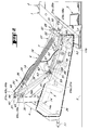
- the cutting machine (1) represented in FIGS. 1 to 4 is a mower (2) comprising in broad outline a cutting mechanism (3), a coupling structure (4), a carrying beam (5), a lightening device (6), a locking device (7) and an operating device (8).
- the coupling structure (4) is intended to be linked to a coupling device (9) of a motor vehicle (10) by means of two lower coupling points (11, 12) and a coupling point upper (13) which are part of said coupling structure (4).
- the cutting mechanism (3) extends, seen from the rear in the direction of advance to work (15) ( Figure 1), to the right of the motor vehicle (10).
- the supporting beam (5) is linked on the one hand to the coupling structure (4) by means of a first articulation (14) with a longitudinal axis (14a) at least substantially horizontal and directed in the direction of advance (15), and on the other hand cutting mechanism (3) by means of a second articulation (17) with a longitudinal axis (17a) at least substantially parallel to said longitudinal axis (14a).
- the support beam (5) extends transversely to the direction of advance (15).
- the lightening device (6) is intended to lighten, in the working position, the cutting mechanism (3) and, in the removal position, to help maintain the hitching structure (4) in a removal position optimal again allowing the mower (2) to be easily coupled to the motor vehicle (10).
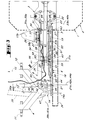
- the lightening device (6) comprises an elastically deformable element (18) which is, according to the example shown, a tension spring (19).
- This tension spring (19) is linked at one of its ends to an upper tie rod (20) itself linked to the coupling structure (4) by means of a third articulation (21) with a longitudinal axis. (2 la) at least substantially parallel to the longitudinal axis (14a) of the first articulation (14).
- the tension spring (19) is linked to a lower tie rod (22) itself linked to the cutting mechanism (3) by means of a fourth articulation (23) with a longitudinal axis ( 23a) at least substantially parallel to the longitudinal axis (14a) of the first articulation (14).
- This operating device (8) comprises an operating element (27) and an operating member (28).
- the operating element (27) is a single-acting hydraulic cylinder (29) linked at one of its ends to the coupling structure (4) by means of a fifth articulation (30) with a longitudinal axis (30a) and to the other of its ends to the operating member (28) by means of a sixth articulation (31) with a longitudinal axis (31a) at least substantially parallel to said longitudinal axis (30a).
- the operating member (28) comprises a mechanism with three levers (33) described in the French patent application 96 05051 filed on April 17, 1996 by the applicant. This operating member (28) will not be described further. For further details, reference is made, if necessary, to the text of said patent application.
- the mower (2) further comprises a transmission device (34) (shown diagrammatically in dashed lines) intended to transmit the rotational movement of a power take-off (not shown) of the motor vehicle (10) to the cutting mechanism ( 3) using a drive shaft (35) with universal joints.
- a transmission device (34) shown diagrammatically in dashed lines
- a power take-off not shown
- a drive shaft 35) with universal joints.
- the locking device (7) for its part, generally comprises a limiter (36) and a lock (37).
- the limiter (36) is intended to limit the pivoting of the coupling structure (4) relative to the support beam (5) around the longitudinal axis (14a) of the first articulation (14).
- the latch (37) is intended to simultaneously lock said pivoting of the hitching structure (4) relative to the support beam (5) and the pivoting of said support beam (5) relative to the cutting mechanism (3) around of the longitudinal axis (17a) of the second articulation (17).
- the limiter (36) comprises a rigid bar (39) extending, in the working position as in the removal position, from the coupling structure (4) downwards in the direction of the cutting mechanism (3).
- the rigid bar (39) is linked to one (40) of its ends (40, 41) to the coupling structure (4) by means of a seventh articulation (42) with a longitudinal axis. (42a) merged with the longitudinal axis (21a) of the third articulation (21) and at the other (41) of its ends (40, 41) to the supporting beam (5) in a sliding manner by means of a link (43).
- joints (21, 42) comprise, according to the example shown, a common journal (44) of longitudinal axis (44a) coincident with the longitudinal axes (21a, 42a).
- This common pin (44) extends right through the upper tie rod (20) of the elastically deformable element (18), through the end (40) of the rigid bar (39) and through of two wings (46, 47) of the coupling structure (4), as shown in FIG. 3.
- the articulations (23, 30, 31) each comprise a respective journal (48, 49, 50), of longitudinal axis (48a, 49a, 50a) respective, coincident with the longitudinal axis (23a, 30a, 31a) corresponding to said joints (23, 30, 31).
- connection (43) also comprises a pin (51) with a longitudinal axis (5 la) at least substantially parallel to the longitudinal axis (14a) of the first articulation (14) and two wings (53, 54) integral with the carrying beam (5).
- the ends (55, 56) of the pin (51) are each guided in a respective oblong hole (57, 58) provided in the corresponding wing (53, 54).
- Each wing (53, 54) is located in the vicinity of the middle part (60) of the support beam (5) so that the longitudinal axis (57a, 58a) of the corresponding oblong hole (57, 58) extends at least substantially orthogonally to the longitudinal axis (14a) of the first articulation (14) and that there remains a space between the two wings (53, 54) supporting said oblong holes (57, 58).
- the latch (37) meanwhile, comprises a lever (61) extending on the one hand, in the removal position, substantially parallel to the carrying beam (5) and being connected on the other hand, to one (62) from its ends (62, 63), to the rigid bar (39) of the limiter (36) by means of an eighth articulation (64) of longitudinal axis (64a) coincident with the longitudinal axis (5 la ) from the journal (51).
- the support beam (5) extends upwards.
- a second bearing surface (69) is intended to come, in the removal position, to bear on a stop (70) provided between the two wings (53, 54) of the link (43) so as to condemn the pivoting of the coupling structure (4) in the direction of the cutting mechanism (3) (that is to say in the clockwise direction of movement) around the longitudinal axis (14a) of the first articulation (14).
- the second bearing surface (69) is, according to the example shown, located on the two wings (65, 66) of the lever (61), while the stop (70) is fixed on the support beam (5) between the two wings (53, 54) of the link (43).
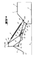
- the mower (2) rests on the ground (S) by means of the cutting mechanism (3), and the hitching structure (4) and the supporting beam (5) are notably maintained in their position of removal as shown in Figures 2, 3 and 4 by means of the tension spring (19) and by means of the locking device (7).
- the operator When the operator wishes to couple the mower (2) to the motor vehicle (10), he links the coupling structure (4) to the coupling device (9) of the motor vehicle (10) to the by means of the two lower coupling points (11, 12) and the upper coupling point (13). To do this, it is preferable to first connect the lowest lower coupling point (11) to the coupling device (9). Then the operator raises the latter somewhat. The pivoting around the longitudinal axes (14a, 17a) of the joints (14, 17) being locked, the mower (2) pivots somewhat around the end of the cutting mechanism (3) furthest from the hitch structure (4), which has the effect of bringing the lower coupling point (12) closer to the coupling device (9) allowing it to be easily linked to the latter. Then, the operator links the upper coupling point (13) to the coupling device (9).
- the operator After having connected the three coupling points (11, 12, 13) of the coupling structure (4) to the coupling device (9) of the motor vehicle (10), the operator raises the said coupling device further (9) so as to pivot the cutting mechanism (3) downwards around the longitudinal axis (17a) of the second articulation (17) to release said cutting mechanism (3) from the first bearing surface (68) (if necessary).
- the operator retracts said lever (61) so as to release the first and second articulation (14, 17) to allow the pivoting of the coupling structure (4) relative to the carrying beam (5) about the longitudinal axis (14a) and the pivoting of the cutting mechanism (3) relative to said carrying beam (5) around the longitudinal axis (17a).
- the operator pivots the lever (61) upwards around the longitudinal axis (64a) of the eighth articulation (64) until in a retracted position in which the longitudinal axis (61a) of said lever (61 ) is substantially coincident with the longitudinal axis (39a) of the rigid bar (39) of the limiter (36).
- the mower (2) being coupled to the motor vehicle (10) and, after the operator has lowered the coupling device (9) of said motor vehicle (10), it is then in the working position as shown in the figure 1.
- lever (61) occupies its retracted position in the working position, in the swath position as well as in the transport position.
- the rigid bar (39) of the limiter (36) and / or the lever (61) of the latch (37) is (are) of adjustable length, and / or that the second surface of support (69) of said lever (61) and / or that the stop (70) is (are) adjustable (s).
Landscapes
- Life Sciences & Earth Sciences (AREA)
- Environmental Sciences (AREA)
- Harvester Elements (AREA)
- Lifting Devices For Agricultural Implements (AREA)
- Apparatuses For Bulk Treatment Of Fruits And Vegetables And Apparatuses For Preparing Feeds (AREA)
- Confectionery (AREA)
- Control And Other Processes For Unpacking Of Materials (AREA)
- Road Repair (AREA)
- Working Measures On Existing Buildindgs (AREA)
- Clamps And Clips (AREA)
Applications Claiming Priority (2)
| Application Number | Priority Date | Filing Date | Title |
|---|---|---|---|
| FR9605660A FR2748187B1 (fr) | 1996-05-02 | 1996-05-02 | Machine de coupe comportant des moyens simplifies permettant de la deposer et de l'atteler a un vehicule moteur |
| FR9605660 | 1996-05-02 |
Publications (2)
| Publication Number | Publication Date |
|---|---|
| EP0804871A1 true EP0804871A1 (de) | 1997-11-05 |
| EP0804871B1 EP0804871B1 (de) | 2002-02-27 |
Family
ID=9491883
Family Applications (1)
| Application Number | Title | Priority Date | Filing Date |
|---|---|---|---|
| EP97440041A Expired - Lifetime EP0804871B1 (de) | 1996-05-02 | 1997-04-28 | Mähmaschine |
Country Status (9)
| Country | Link |
|---|---|
| US (1) | US5896733A (de) |
| EP (1) | EP0804871B1 (de) |
| JP (1) | JP3817624B2 (de) |
| AT (1) | ATE213587T1 (de) |
| AU (1) | AU711624B2 (de) |
| DE (1) | DE69710633T2 (de) |
| DK (1) | DK0804871T3 (de) |
| ES (1) | ES2170931T3 (de) |
| FR (1) | FR2748187B1 (de) |
Families Citing this family (8)
| Publication number | Priority date | Publication date | Assignee | Title |
|---|---|---|---|---|
| FR2794934B1 (fr) | 1999-06-17 | 2001-08-10 | Kuhn Sa | Machine agricole du type faucheuse ou faucheuse- conditionnneuse comportant un organe d'amortissement |
| JP4588278B2 (ja) * | 1999-07-16 | 2010-11-24 | エヌエックスピー ビー ヴィ | アナログ−デジタル変換器 |
| FR2802766B1 (fr) | 1999-12-23 | 2002-09-27 | Kuhn Sa | Element de coupe d'une machine de coupe de vegetaux rotative et machine de coupe de vegetaux rotative comportant un tel element de coupe |
| FR2867350B1 (fr) * | 2004-03-09 | 2006-04-28 | Kuhn Sa | Machine de coupe, notamment une faucheuse agricole, dont la mise en position de transport est simplifiee |
| FR2881021B1 (fr) * | 2005-01-26 | 2007-02-23 | Kuhn Sa Sa | Faucheuse avec dispositif de depliage et de repliage perfectionne |
| FR2993136B1 (fr) * | 2012-07-12 | 2015-04-10 | Kuhn Sa | Machine de coupe comportant un dispositif de deplacement perfectionne |
| US12538867B2 (en) * | 2022-08-10 | 2026-02-03 | Deere & Company | Mower with curtain assembly |
| CA3228933A1 (en) * | 2023-02-13 | 2025-04-17 | Macdon Industries Ltd | Floating cutterbar on rotary header |
Citations (5)
| Publication number | Priority date | Publication date | Assignee | Title |
|---|---|---|---|---|
| FR2357163A1 (fr) * | 1976-07-07 | 1978-02-03 | Bautz Gmbh Josef | Faucheuse a toupies pour fixation a la suspension trois-points d'un tracteur |
| GB2157936A (en) * | 1984-05-03 | 1985-11-06 | Claas Saulgau Gmbh | Mowing mechanism |
| DE9112331U1 (de) * | 1991-10-04 | 1991-12-12 | Maschinenfabriken Bernard Krone Gmbh, 4441 Spelle | Mähmaschine |
| DE4110430A1 (de) * | 1991-03-29 | 1992-10-01 | Poettinger Alois Landmasch | Maehwerk |
| FR2687039A1 (fr) * | 1992-02-12 | 1993-08-13 | Kuhn Sa | Faucheuse avec un dispositif de verrouillage perfectionne. |
Family Cites Families (13)
| Publication number | Priority date | Publication date | Assignee | Title |
|---|---|---|---|---|
| FR2458981A1 (fr) * | 1979-06-19 | 1981-01-09 | Kuhn Sa | Bati de machine agricole |
| FR2496391A1 (fr) * | 1980-12-19 | 1982-06-25 | Kuhn Sa | Perfectionnement aux faucheuses |
| FR2502888A1 (fr) * | 1981-04-02 | 1982-10-08 | Kuhn Sa | Barre de coupe a protecteur de disque lateral amovible |
| FR2598058B1 (fr) * | 1986-05-02 | 1989-10-13 | Kuhn Sa | Faucheuse munie d'au moins un organe de coupe surmonte par un tambour rotatif |
| FR2624688B1 (fr) * | 1987-12-21 | 1990-05-18 | Kuhn Sa | Faucheuse avec rigidification perfectionnee de la barre de coupe |
| FR2626137B1 (fr) * | 1988-01-22 | 1991-09-06 | Kuhn Sa | Faucheuse rotative comportant des organes de coupe s'etendant au-dessus d'un carter par l'intermediaire de paliers de guidage et d'entrainement |
| FR2628596B1 (fr) * | 1988-03-15 | 1991-09-06 | Kuhn Sa | Faucheuse a entrainement direct |
| FR2638056B1 (fr) * | 1988-10-26 | 1991-06-07 | Kuhn Sa | Faucheuse avec montage perfectionne des organes de coupe |
| FR2642610B1 (fr) * | 1989-02-07 | 1991-05-17 | Kuhn Sa | Faucheuse avec dispositif de securite a declenchement |
| FR2675980B1 (fr) * | 1991-04-30 | 1998-07-03 | Kuhn Sa | Machine de coupe perfectionnee avec structure d'attelage pivotante. |
| US5203150A (en) * | 1992-01-06 | 1993-04-20 | Vermeer Manufacturing Company | Hinged shield for crop cutting apparatus |
| FR2726152B1 (fr) * | 1994-10-28 | 1997-01-24 | Kuhn Sa | Machine agricole destinee a la coupe de vegetaux avec dispositif de protection perfectionne |
| FR2729817B1 (fr) * | 1995-01-27 | 1997-04-11 | Kuhn Sa | Machine de coupe avec dispositif de commande de l'action d'un ressort d'allegement du mecanisme de coupe |
-
1996
- 1996-05-02 FR FR9605660A patent/FR2748187B1/fr not_active Expired - Fee Related
-
1997
- 1997-04-25 US US08/840,929 patent/US5896733A/en not_active Expired - Lifetime
- 1997-04-28 DE DE69710633T patent/DE69710633T2/de not_active Expired - Lifetime
- 1997-04-28 AT AT97440041T patent/ATE213587T1/de active
- 1997-04-28 EP EP97440041A patent/EP0804871B1/de not_active Expired - Lifetime
- 1997-04-28 DK DK97440041T patent/DK0804871T3/da active
- 1997-04-28 ES ES97440041T patent/ES2170931T3/es not_active Expired - Lifetime
- 1997-05-01 AU AU19967/97A patent/AU711624B2/en not_active Ceased
- 1997-05-02 JP JP13042397A patent/JP3817624B2/ja not_active Expired - Fee Related
Patent Citations (6)
| Publication number | Priority date | Publication date | Assignee | Title |
|---|---|---|---|---|
| FR2357163A1 (fr) * | 1976-07-07 | 1978-02-03 | Bautz Gmbh Josef | Faucheuse a toupies pour fixation a la suspension trois-points d'un tracteur |
| GB2157936A (en) * | 1984-05-03 | 1985-11-06 | Claas Saulgau Gmbh | Mowing mechanism |
| DE4110430A1 (de) * | 1991-03-29 | 1992-10-01 | Poettinger Alois Landmasch | Maehwerk |
| DE9112331U1 (de) * | 1991-10-04 | 1991-12-12 | Maschinenfabriken Bernard Krone Gmbh, 4441 Spelle | Mähmaschine |
| FR2687039A1 (fr) * | 1992-02-12 | 1993-08-13 | Kuhn Sa | Faucheuse avec un dispositif de verrouillage perfectionne. |
| EP0556143A1 (de) * | 1992-02-12 | 1993-08-18 | Kuhn S.A. | Mähmaschine mit einer verbesserten Verriegelungsvorrichtung |
Also Published As
| Publication number | Publication date |
|---|---|
| JPH1042649A (ja) | 1998-02-17 |
| ATE213587T1 (de) | 2002-03-15 |
| EP0804871B1 (de) | 2002-02-27 |
| JP3817624B2 (ja) | 2006-09-06 |
| DK0804871T3 (da) | 2002-06-17 |
| FR2748187A1 (fr) | 1997-11-07 |
| DE69710633D1 (de) | 2002-04-04 |
| DE69710633T2 (de) | 2003-02-06 |
| ES2170931T3 (es) | 2002-08-16 |
| FR2748187B1 (fr) | 1998-07-31 |
| US5896733A (en) | 1999-04-27 |
| AU711624B2 (en) | 1999-10-21 |
| AU1996797A (en) | 1997-11-06 |
Similar Documents
| Publication | Publication Date | Title |
|---|---|---|
| EP0178239B2 (de) | Verfahren zum Umbauen einer Erntemaschine von einer Arbeitsposition zu einer Transportposition und Erntemaschine, die dieses Verfahren anwendet | |
| EP0809928B1 (de) | Mähmaschine | |
| EP0382666B1 (de) | Mähmaschine mit selbstauslösender Sicherheitsvorrichtung | |
| EP0511922B1 (de) | Mähmaschine mit schwenkbarer Kupplungsstruktur | |
| CA2198923C (fr) | Machine agricole avec moyen de liaison a un vehicule tracteur et carter de renvoi pivotants | |
| EP0486414A1 (de) | Leicht zur Bodenoberfläche anpassende Landmaschine mit einem schwenkenden Getriebe | |
| EP0654205A1 (de) | Landwirtschaftliche Maschine mit einer verbesserten Deichsel | |
| EP0709018A1 (de) | Landmaschine zum Schneiden von Erntegut mit einer verbesserten Schutzvorrichtung | |
| EP0552120B1 (de) | Heumaschine mit dynamischer Entlastungsvorrichtung | |
| EP0451074B1 (de) | Mähmaschine mit verbessertem Tragrahmen | |
| EP0804871B1 (de) | Mähmaschine | |
| EP1965630B1 (de) | Landwirtschaftsvorrichtung mit einer verbesserten kupplungsstruktur | |
| EP0839443B1 (de) | Mähmaschine | |
| EP0910940B1 (de) | Landwirtschaftmaschine | |
| EP4147546B1 (de) | Drehpflug mit verbesserter sicherheit bei konfigurationsänderungen | |
| EP0653343B1 (de) | Steuereinrichtung zum Lenken der Hinterräder eines Anhängers | |
| EP0880879A1 (de) | Manövriervorrichtung für landwirtschaftliche Maschine | |
| EP2959759B1 (de) | Landwirtschaftliche maschine, die mit einer zentriervorrichtung ausgestattet ist | |
| EP3713390B1 (de) | Landwirtschaftliche maschine mit einem sicherheitssystem mit verbesserter auslösekinematik | |
| EP0801887B1 (de) | Mähmaschine | |
| FR2489080A1 (fr) | Dispositif de raccordement permettant d'atteler des machines agricoles a un vehicule tracteur | |
| FR2912870A1 (fr) | Machine de coupe de vegetaux, notamment broyeur-debroussailleur | |
| FR2883698A1 (fr) | Dispositif d'attelage permettant d'atteler un outil a un vehicule |
Legal Events
| Date | Code | Title | Description |
|---|---|---|---|
| PUAI | Public reference made under article 153(3) epc to a published international application that has entered the european phase |
Free format text: ORIGINAL CODE: 0009012 |
|
| AK | Designated contracting states |
Kind code of ref document: A1 Designated state(s): AT BE DE DK ES FR GB IT NL |
|
| 17P | Request for examination filed |
Effective date: 19980422 |
|
| 17Q | First examination report despatched |
Effective date: 20000803 |
|
| GRAG | Despatch of communication of intention to grant |
Free format text: ORIGINAL CODE: EPIDOS AGRA |
|
| GRAG | Despatch of communication of intention to grant |
Free format text: ORIGINAL CODE: EPIDOS AGRA |
|
| GRAH | Despatch of communication of intention to grant a patent |
Free format text: ORIGINAL CODE: EPIDOS IGRA |
|
| GRAH | Despatch of communication of intention to grant a patent |
Free format text: ORIGINAL CODE: EPIDOS IGRA |
|
| REG | Reference to a national code |
Ref country code: GB Ref legal event code: IF02 |
|
| GRAA | (expected) grant |
Free format text: ORIGINAL CODE: 0009210 |
|
| AK | Designated contracting states |
Kind code of ref document: B1 Designated state(s): AT BE DE DK ES FR GB IT NL |
|
| REF | Corresponds to: |
Ref document number: 213587 Country of ref document: AT Date of ref document: 20020315 Kind code of ref document: T |
|
| REF | Corresponds to: |
Ref document number: 69710633 Country of ref document: DE Date of ref document: 20020404 |
|
| GBT | Gb: translation of ep patent filed (gb section 77(6)(a)/1977) |
Effective date: 20020502 |
|
| REG | Reference to a national code |
Ref country code: DK Ref legal event code: T3 |
|
| REG | Reference to a national code |
Ref country code: ES Ref legal event code: FG2A Ref document number: 2170931 Country of ref document: ES Kind code of ref document: T3 |
|
| PLBE | No opposition filed within time limit |
Free format text: ORIGINAL CODE: 0009261 |
|
| STAA | Information on the status of an ep patent application or granted ep patent |
Free format text: STATUS: NO OPPOSITION FILED WITHIN TIME LIMIT |
|
| 26N | No opposition filed |
Effective date: 20021128 |
|
| REG | Reference to a national code |
Ref country code: FR Ref legal event code: PLFP Year of fee payment: 19 |
|
| PGFP | Annual fee paid to national office [announced via postgrant information from national office to epo] |
Ref country code: DK Payment date: 20150320 Year of fee payment: 19 Ref country code: NL Payment date: 20150319 Year of fee payment: 19 |
|
| PGFP | Annual fee paid to national office [announced via postgrant information from national office to epo] |
Ref country code: GB Payment date: 20150324 Year of fee payment: 19 Ref country code: FR Payment date: 20150319 Year of fee payment: 19 |
|
| PGFP | Annual fee paid to national office [announced via postgrant information from national office to epo] |
Ref country code: BE Payment date: 20150320 Year of fee payment: 19 |
|
| PGFP | Annual fee paid to national office [announced via postgrant information from national office to epo] |
Ref country code: DE Payment date: 20150319 Year of fee payment: 19 Ref country code: ES Payment date: 20150408 Year of fee payment: 19 |
|
| PGFP | Annual fee paid to national office [announced via postgrant information from national office to epo] |
Ref country code: AT Payment date: 20150320 Year of fee payment: 19 |
|
| PG25 | Lapsed in a contracting state [announced via postgrant information from national office to epo] |
Ref country code: BE Free format text: LAPSE BECAUSE OF NON-PAYMENT OF DUE FEES Effective date: 20160430 |
|
| PGFP | Annual fee paid to national office [announced via postgrant information from national office to epo] |
Ref country code: IT Payment date: 20160324 Year of fee payment: 20 |
|
| REG | Reference to a national code |
Ref country code: DE Ref legal event code: R119 Ref document number: 69710633 Country of ref document: DE |
|
| REG | Reference to a national code |
Ref country code: DK Ref legal event code: EBP Effective date: 20160430 |
|
| REG | Reference to a national code |
Ref country code: NL Ref legal event code: MM Effective date: 20160501 |
|
| REG | Reference to a national code |
Ref country code: AT Ref legal event code: MM01 Ref document number: 213587 Country of ref document: AT Kind code of ref document: T Effective date: 20160428 |
|
| GBPC | Gb: european patent ceased through non-payment of renewal fee |
Effective date: 20160428 |
|
| REG | Reference to a national code |
Ref country code: FR Ref legal event code: ST Effective date: 20161230 |
|
| PG25 | Lapsed in a contracting state [announced via postgrant information from national office to epo] |
Ref country code: GB Free format text: LAPSE BECAUSE OF NON-PAYMENT OF DUE FEES Effective date: 20160428 Ref country code: NL Free format text: LAPSE BECAUSE OF NON-PAYMENT OF DUE FEES Effective date: 20160501 Ref country code: DE Free format text: LAPSE BECAUSE OF NON-PAYMENT OF DUE FEES Effective date: 20161101 Ref country code: FR Free format text: LAPSE BECAUSE OF NON-PAYMENT OF DUE FEES Effective date: 20160502 |
|
| PG25 | Lapsed in a contracting state [announced via postgrant information from national office to epo] |
Ref country code: AT Free format text: LAPSE BECAUSE OF NON-PAYMENT OF DUE FEES Effective date: 20160428 |
|
| PG25 | Lapsed in a contracting state [announced via postgrant information from national office to epo] |
Ref country code: DK Free format text: LAPSE BECAUSE OF NON-PAYMENT OF DUE FEES Effective date: 20160430 |
|
| REG | Reference to a national code |
Ref country code: ES Ref legal event code: FD2A Effective date: 20180507 |
|
| PG25 | Lapsed in a contracting state [announced via postgrant information from national office to epo] |
Ref country code: ES Free format text: LAPSE BECAUSE OF NON-PAYMENT OF DUE FEES Effective date: 20160429 |