EP0804706B1 - Fuel-conveying incineration grate for incinerating plants, especially for waste materials - Google Patents
Fuel-conveying incineration grate for incinerating plants, especially for waste materials Download PDFInfo
- Publication number
- EP0804706B1 EP0804706B1 EP95942060A EP95942060A EP0804706B1 EP 0804706 B1 EP0804706 B1 EP 0804706B1 EP 95942060 A EP95942060 A EP 95942060A EP 95942060 A EP95942060 A EP 95942060A EP 0804706 B1 EP0804706 B1 EP 0804706B1
- Authority
- EP
- European Patent Office
- Prior art keywords
- grate
- beams
- heat
- incineration
- transmission medium
- Prior art date
- Legal status (The legal status is an assumption and is not a legal conclusion. Google has not performed a legal analysis and makes no representation as to the accuracy of the status listed.)
- Expired - Lifetime
Links
- 239000002699 waste material Substances 0.000 title 1
- 239000000446 fuel Substances 0.000 claims abstract 4
- 238000002485 combustion reaction Methods 0.000 claims abstract 2
- 239000002826 coolant Substances 0.000 claims 1
- 238000010438 heat treatment Methods 0.000 claims 1
- XLYOFNOQVPJJNP-UHFFFAOYSA-N water Substances O XLYOFNOQVPJJNP-UHFFFAOYSA-N 0.000 claims 1
Images

Classifications
-
- F—MECHANICAL ENGINEERING; LIGHTING; HEATING; WEAPONS; BLASTING
- F23—COMBUSTION APPARATUS; COMBUSTION PROCESSES
- F23H—GRATES; CLEANING OR RAKING GRATES
- F23H3/00—Grates with hollow bars
- F23H3/02—Grates with hollow bars internally cooled
-
- F—MECHANICAL ENGINEERING; LIGHTING; HEATING; WEAPONS; BLASTING
- F23—COMBUSTION APPARATUS; COMBUSTION PROCESSES
- F23H—GRATES; CLEANING OR RAKING GRATES
- F23H7/00—Inclined or stepped grates
- F23H7/06—Inclined or stepped grates with movable bars disposed parallel to direction of fuel feeding
- F23H7/08—Inclined or stepped grates with movable bars disposed parallel to direction of fuel feeding reciprocating along their axes
-
- F—MECHANICAL ENGINEERING; LIGHTING; HEATING; WEAPONS; BLASTING
- F23—COMBUSTION APPARATUS; COMBUSTION PROCESSES
- F23G—CREMATION FURNACES; CONSUMING WASTE PRODUCTS BY COMBUSTION
- F23G2203/00—Furnace arrangements
- F23G2203/101—Furnace arrangements with stepped or inclined grate
-
- F—MECHANICAL ENGINEERING; LIGHTING; HEATING; WEAPONS; BLASTING
- F23—COMBUSTION APPARATUS; COMBUSTION PROCESSES
- F23H—GRATES; CLEANING OR RAKING GRATES
- F23H2900/00—Special features of combustion grates
- F23H2900/03021—Liquid cooled grates
Definitions
- the present invention relates to a fuel-conveying incineration grate for incinerating plants, especially for waste materials, of the kind set forth in the preamble of claim 1.
- incineration grates of the kind referred to above are well-known and are normally used with two or more sections mutually overlapping, the uppermost section functioning as an infeed grate apportioning the fuel into the incinerating plant from a fuel shaft above the upper part of the grate, whilst the function of combustion per se is served by the lower section or sections, the lowermost section also discharging the solid products of combustion, such as ashes and slags, to suitable removal devices.
- every other grate beam is reciprocable longitudinally, while the remaining grate beams are stationary.
- the grate surface is formed by a number of grate blocks composed of grate rods, each block comprising two steps of the stepped surface.
- US-A-2,240,590 describes a fluid cooled grate beam comprising two longitudinally extending ducts for the cooling medium provided immediately below the grate surface of each grate beam and in heat transmitting contact with said surface and the lateral surfaces of the grate beam, as well as connecting points at one end of the grate beam for the flow of cooling medium towards and away from said ducts.
- these grate beams are not placed sealingly close to each other along the lateral surfaces.
- the grate beams are provided with primary air openings along the lateral surfaces. This will result in a tendency to move material on the grate in between the grate beams which will lead to increased wear on the lateral surfaces of the grate beams.
- FR-A-739,654 describes another fluid cooled grate beam comprising flat lateral surfaces but these surfaces are placed with spaces between them.
- incinerating plants for waste material especially the infeed grate, i.e. the uppermost grate section in the plant, is subject to extremely inhomogeneous heat influences; this is due to its function and position in the plant as well as variations in the calorific value of the waste material being fed in by this grate, because the processes taking place on the infeed grate comprise both a drying of the waste material and an initial gasification and ignition of the latter, and the manner, in which all this proceeds and hence the heating of the grate, depends to a high degree of the (net) calorific value of the waste material, i.e. especially its moisture content.
- incineration grates of the kind referred to initially normally comprise facilities for pressing the grate beams in each section together in the lateral direction, this also making it possible to accommodate attrition on the lateral surfaces of the grate beams.
- This attrition being - of course - due to the relative movements of the grate beams, will, because of their material properties, be a minimum at a relatively low temperature.
- the grate surface as in the grate disclosed in US patent specification No. 4,471,704, could consist of a number of separate grate elements, each in heat-conducting contact with the longitudinal ducts
- the embodiment set forth in claim 2 is preferred, as it simplifies the construction and facilitates assembly and maintenance.
- the heat-transmission medium flows downwardly along one side of the grate beam and upwardly along its opposite side, thus contributing further to reducing any temperature differences along the length of the grate surface.
- the embodiment set forth in claim 6 is preferred if the temperature, at which the heat-transmission medium is supplied to the grate beam in the incineration grate, is lower than the average temperature of the grate surfaces. In addition to the primary effect of the circulating heat-transmission medium, viz. an equalization of temperature along the length of the grate surface, this will result in a cooling of the latter and of the lateral surfaces and hence a reduction of the attrition on the relatively moving lateral surfaces on adjacent grate beams.
- the embodiment set forth in claim 7 may be preferred, when the supply temperature of the heat-transmission medium is higher than the average temperature of the grate surfaces.
- This can be advantageous in infeed grates, when waste material with a high moisture content is to be incinerated, as this material will be receiving heat from the heated grate surfaces for the evaporation of the moisture already when being delivered from the shaft.
- This heating medium may then be a heat-transmission medium having circulated in a succeeding grate section in the incinerating plant.
- the heat-transmission medium may be any suitable fluid, such as a gas, a liquid or a two-phase medium, but in practice it is preferred, as indicated in claim 8, to use water as the heat-transmission medium, preferably alone in the liquid phase. Since this water should preferably have been treated in the same manner as feed water for boilers so as to avoid scale being deposited in the ducts and in the inlet and outlet conduits, it may advantageously after having circulated in the incineration grate be supplied to the economizer of the incinerating plant. Alternatively, it may be made to flow through a heat exchanger for cooling and supplying useful heat.
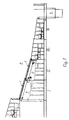
- FIG. 1 is a side view showing an incineration grate according to the invention consisting of four sections I, II, III and IV, in which the grates in each section consist of a number of grate beams generally designated 1, the side surfaces of which are closely adjacent to each other across the width of the grate.
- a stationary grate beam 1 is shown in section I, while a reciprocable grate beam 1 is shown in section II.
- these grates are of similar construction.
- the grate beams 1 have a stepped grate surface and extend obliquely downward in the direction of movement of the fuel, the grate beams 1 in a preceding section overlapping grate beams 1 in a succeeding section.
- the grate section I is an infeed grate feeding-in refuse to be incinerated from a chute or shaft (not shown) into the incinerating plant. From the grate section IV, un-combusted material, i.e. slags and ashes, fall into a slag pit S, from which it may be removed e.g. by means of a conveyor (not shown).
- Figure 2 is a part-sectional view at a larger scale through a grate section in an incineration grate according to the invention, in which reciprocable grate beams 1 are placed between stationary grate beams 1 as shown and described in the previously mentioned US patent publication No. 4,494,469.
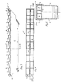
- Figures 3, 4 and 5 show a grate beam 1 in longitudinal section, in plan view and in cross-section, respectively.
- the grate beam 1 comprises two main sideboards 2, each having affixed thereto an upper sideboard 3, of which the latter are in slidable abutment against corresponding upper sideboards on adjacent grate beams in the grate.
- the top edges of the upper sideboards 3 are stepped, and an equally stepped, unitary grate plate 4 is secured to these top edges.
- a primary-air opening 5 extending in the longitudinal direction of the grate plate 4 is formed in the centre of each of the latter's steps. The primary-air openings may be omitted in some of these steps, thus in the uppermost steps in infeed grates, i.e. the steps to the left in Figures 3 and 4, on which no combustion is taking place.
- Two ducts 6 and 7 extend below, along the full length of and in heat-transferring contact with the grate plate 4 and the upper sideboards 3, the top sides of these ducts thus being stepped in the same manner as the grate plate 4.
- the ducts 6 and 7 are connected to each other through a tubular duct 10, the ducts 6 and 7 being separated by an interspace 11 extending below the primary-air openings 5 in the grate plate 4 and thus connecting the primary-air openings 5 with the primary-air space P below the incineration grate and the grate beam 1.
- the upper end of the grate beam 1 i.e.
- each of the ducts 6 and 7 have connecting points 13 and 12, respectively - in Figures 3 and 4 shown purely diagrammatically - for supplying a heat-transmission medium to the ducts 6 and 7 and removing said medium from them.
- the water thus having been heated will, when flowing upwardly through the duct 7, cause the upper part of the adjacent upper sideboards 3 and the overlying part on the grate plate 4 to be heated, thus causing a thermal expansion of the grate beam 1 in this region, especially an increase of its width between the outside surfaces of the upper sideboards 3.
- this makes it possible to achieve an equalization of the width of the grate beam between the outside surfaces of the upper sideboards 3 along the length of the beam, thus making it possible to overcome or at least reduce the disadvantage of lack of sealing between adjacent grate beams 1.
- heated water is made to flow through the ducts 6 and 7 in the grate beams 1 of the infeed grate, e.g. water having been heated by circulating through grate beams 1 in a succeeding grate section in the incinerating plant, it is also in this manner possible to achieve the desired equalization of the outside width of each grate beam 1 along its length and hence the desired sealing between adjacent grate beams 1 in the infeed grate.
- the heated grate beams 1 will then also be able to accelerate the evaporation of moisture from the waste material, thus ensuring a normal process of drying, gasification and ignition of the waste material on the infeed grate.
Landscapes
- Engineering & Computer Science (AREA)
- Chemical & Material Sciences (AREA)
- Combustion & Propulsion (AREA)
- Mechanical Engineering (AREA)
- General Engineering & Computer Science (AREA)
- Incineration Of Waste (AREA)
- Solid-Fuel Combustion (AREA)
- Gasification And Melting Of Waste (AREA)
Applications Claiming Priority (4)
| Application Number | Priority Date | Filing Date | Title |
|---|---|---|---|
| DK86/95 | 1995-01-24 | ||
| DK008695A DK171048B1 (da) | 1995-01-24 | 1995-01-24 | Brændselstransporterende forbrændingsrist til forbrændingsanlæg, navnlig affaldsforbrændingsanlæg |
| DK8695 | 1995-01-24 | ||
| PCT/DK1995/000522 WO1996023174A1 (en) | 1995-01-24 | 1995-12-28 | Fuel-conveying incineration grate for incinerating plants, especially for waste materials |
Publications (2)
| Publication Number | Publication Date |
|---|---|
| EP0804706A1 EP0804706A1 (en) | 1997-11-05 |
| EP0804706B1 true EP0804706B1 (en) | 1998-09-23 |
Family
ID=8089583
Family Applications (1)
| Application Number | Title | Priority Date | Filing Date |
|---|---|---|---|
| EP95942060A Expired - Lifetime EP0804706B1 (en) | 1995-01-24 | 1995-12-28 | Fuel-conveying incineration grate for incinerating plants, especially for waste materials |
Country Status (8)
| Country | Link |
|---|---|
| US (1) | US5899149A (ja) |
| EP (1) | EP0804706B1 (ja) |
| JP (1) | JP3739397B2 (ja) |
| AT (1) | ATE171538T1 (ja) |
| AU (1) | AU4327696A (ja) |
| DE (1) | DE69505016T2 (ja) |
| DK (1) | DK171048B1 (ja) |
| WO (1) | WO1996023174A1 (ja) |
Families Citing this family (8)
| Publication number | Priority date | Publication date | Assignee | Title |
|---|---|---|---|---|
| DE19753981C2 (de) * | 1997-12-05 | 2000-04-06 | Alstom Energy Syst Gmbh | Flüssigkeitsgekühlte Rostplatte |
| US6981455B2 (en) * | 2002-03-08 | 2006-01-03 | Lefcort Malcolm D | Two-stage wet waste gasifier and burner |
| JP4948527B2 (ja) | 2005-04-13 | 2012-06-06 | バブコック アンド ウイルコックス ボルンド エイ/エス | 焼却又は燃焼プラント |
| WO2007107024A1 (de) * | 2006-03-17 | 2007-09-27 | Doikos Investments Ltd. | Flüssigkeitsgekühlter rost mit verschleissplatten |
| EP2034243A1 (en) * | 2007-09-10 | 2009-03-11 | Babcock & Wilcox Vølund A/S | Stepped grate beam for a combustion grate |
| AT514546B1 (de) * | 2013-08-19 | 2015-02-15 | Hochgatterer Manuel | Brenner für Festbrennstoffe, insbesondere Hackgut |
| JP7199153B2 (ja) * | 2018-03-29 | 2023-01-05 | 川崎重工業株式会社 | 焼却炉 |
| CN114893778B (zh) * | 2022-06-07 | 2025-02-11 | 上海康恒环境股份有限公司 | 一种炉排框架、炉排段和焚烧炉 |
Family Cites Families (12)
| Publication number | Priority date | Publication date | Assignee | Title |
|---|---|---|---|---|
| FR739654A (ja) * | 1900-01-01 | |||
| US667399A (en) * | 1897-08-23 | 1901-02-05 | Sigmund Kanitz | Furnace-grate. |
| US2387383A (en) * | 1936-09-03 | 1945-10-23 | American Eng Co Ltd | Stoker |
| US2240590A (en) * | 1938-05-02 | 1941-05-06 | George W Wallace | Automatic fluid cooled grate |
| GB2120764B (en) * | 1982-05-13 | 1985-08-14 | Voelund Miljoeteknik | A stepped grate for an incinerator plant |
| US4471704A (en) * | 1982-06-21 | 1984-09-18 | Clear Air, Inc. | Reciprocating grate systems for furnaces and incinerators |
| JPS5824720A (ja) * | 1982-07-12 | 1983-02-14 | Takuma Co Ltd | 階段式中空スト−カ |
| JPS60147015A (ja) * | 1984-01-09 | 1985-08-02 | Takuma Co Ltd | 並列揺動式階段スト−カ |
| JPH02106613A (ja) * | 1988-10-13 | 1990-04-18 | Hitachi Zosen Corp | 焼却炉の火格子構造 |
| US4955296A (en) * | 1988-12-01 | 1990-09-11 | Barlow James L | Incinerator grate assembly |
| DE4242374A1 (ja) * | 1992-01-31 | 1993-08-05 | Kloeckner Humboldt Deutz Ag | |
| DE4400992C1 (de) * | 1994-01-14 | 1995-05-11 | Noell Abfall & Energietech | Roststab und Rost mit Kühleinrichtung |
-
1995
- 1995-01-24 DK DK008695A patent/DK171048B1/da not_active IP Right Cessation
- 1995-12-28 US US08/860,245 patent/US5899149A/en not_active Expired - Fee Related
- 1995-12-28 JP JP52255296A patent/JP3739397B2/ja not_active Expired - Fee Related
- 1995-12-28 EP EP95942060A patent/EP0804706B1/en not_active Expired - Lifetime
- 1995-12-28 AT AT95942060T patent/ATE171538T1/de not_active IP Right Cessation
- 1995-12-28 AU AU43276/96A patent/AU4327696A/en not_active Abandoned
- 1995-12-28 WO PCT/DK1995/000522 patent/WO1996023174A1/en not_active Ceased
- 1995-12-28 DE DE69505016T patent/DE69505016T2/de not_active Expired - Fee Related
Also Published As
| Publication number | Publication date |
|---|---|
| DE69505016T2 (de) | 1999-02-18 |
| DK171048B1 (da) | 1996-04-29 |
| JPH10512662A (ja) | 1998-12-02 |
| EP0804706A1 (en) | 1997-11-05 |
| AU4327696A (en) | 1996-08-14 |
| WO1996023174A1 (en) | 1996-08-01 |
| DK8695A (da) | 1996-04-29 |
| US5899149A (en) | 1999-05-04 |
| ATE171538T1 (de) | 1998-10-15 |
| DE69505016D1 (de) | 1998-10-29 |
| JP3739397B2 (ja) | 2006-01-25 |
Similar Documents
| Publication | Publication Date | Title |
|---|---|---|
| US4823740A (en) | Thermal reactor | |
| US5913274A (en) | Incineration grate with internal cooling | |
| EP0804706B1 (en) | Fuel-conveying incineration grate for incinerating plants, especially for waste materials | |
| RU2459659C1 (ru) | Котел с циркулирующим псевдоожиженным слоем | |
| CZ320294A3 (en) | Method of burning waste and a grate for making the same | |
| US5284103A (en) | Bio-mass burner construction | |
| JP3990463B2 (ja) | 水冷燃焼火格子 | |
| EP1012502B1 (en) | Grate construction of a fluidized bed boiler | |
| US4876972A (en) | Grate bar element for a sliding grate furnace for garbage incineration | |
| US5617801A (en) | Cooled grate block | |
| HU220436B (hu) | Folyadékkal hűtött rostélylap | |
| JPH0370124B2 (ja) | ||
| NO302147B1 (no) | Anordning ved forbrenningsovn, samt fremgangsmåte ved söppelforbrenning | |
| AU2008252503A1 (en) | System for dry extracting / cooling heterogeneous material ashes with control of the air inlet in the combustion chamber | |
| JPH02106613A (ja) | 焼却炉の火格子構造 | |
| US5103744A (en) | Apparatus for the combustion and/or decomposition of fuel by heat, especially of solid fuels | |
| JPH06100325B2 (ja) | 焼却炉の空気制御 | |
| EP0575470B1 (en) | A solid fuel stoker | |
| CN101311626B (zh) | 整体式流化床灰冷却器 | |
| KR20010030387A (ko) | 고체물질 소각용 화격자 및, 노 챔버용 화격자의 수냉 방법 | |
| US4889060A (en) | Web for rotary combustor | |
| EP4303492A1 (en) | Plate-formed grate element for a movable grate of a furnace | |
| RU2231714C2 (ru) | Топка для сжигания твердого топлива в кипящем слое | |
| RU2319067C1 (ru) | Топочное устройство | |
| EA038810B1 (ru) | Система теплового котла с псевдоожиженным слоем и способ сжигания топлива по меньшей мере двух типов в тепловом котле с псевдоожиженным слоем |
Legal Events
| Date | Code | Title | Description |
|---|---|---|---|
| TPAD | Observations filed by third parties |
Free format text: ORIGINAL CODE: EPIDOS TIPA |
|
| PUAI | Public reference made under article 153(3) epc to a published international application that has entered the european phase |
Free format text: ORIGINAL CODE: 0009012 |
|
| 17P | Request for examination filed |
Effective date: 19970825 |
|
| AK | Designated contracting states |
Kind code of ref document: A1 Designated state(s): AT CH DE FR GB IT LI NL SE |
|
| GRAG | Despatch of communication of intention to grant |
Free format text: ORIGINAL CODE: EPIDOS AGRA |
|
| 17Q | First examination report despatched |
Effective date: 19971202 |
|
| GRAG | Despatch of communication of intention to grant |
Free format text: ORIGINAL CODE: EPIDOS AGRA |
|
| GRAH | Despatch of communication of intention to grant a patent |
Free format text: ORIGINAL CODE: EPIDOS IGRA |
|
| GRAH | Despatch of communication of intention to grant a patent |
Free format text: ORIGINAL CODE: EPIDOS IGRA |
|
| GRAA | (expected) grant |
Free format text: ORIGINAL CODE: 0009210 |
|
| AK | Designated contracting states |
Kind code of ref document: B1 Designated state(s): AT CH DE FR GB IT LI NL SE |
|
| REF | Corresponds to: |
Ref document number: 171538 Country of ref document: AT Date of ref document: 19981015 Kind code of ref document: T |
|
| REG | Reference to a national code |
Ref country code: CH Ref legal event code: EP |
|
| REF | Corresponds to: |
Ref document number: 69505016 Country of ref document: DE Date of ref document: 19981029 |
|
| REG | Reference to a national code |
Ref country code: CH Ref legal event code: NV Representative=s name: BUGNION S.A. |
|
| ET | Fr: translation filed | ||
| PLBE | No opposition filed within time limit |
Free format text: ORIGINAL CODE: 0009261 |
|
| STAA | Information on the status of an ep patent application or granted ep patent |
Free format text: STATUS: NO OPPOSITION FILED WITHIN TIME LIMIT |
|
| 26N | No opposition filed | ||
| REG | Reference to a national code |
Ref country code: GB Ref legal event code: 732E |
|
| REG | Reference to a national code |
Ref country code: CH Ref legal event code: PUE Owner name: VOLUND ECOLOGY SYSTEMS A/S TRANSFER- BABCOCK & WIL |
|
| REG | Reference to a national code |
Ref country code: GB Ref legal event code: IF02 |
|
| NLS | Nl: assignments of ep-patents |
Owner name: BABCOCK & WILCOX VOLUND APS |
|
| REG | Reference to a national code |
Ref country code: FR Ref legal event code: TP |
|
| PGFP | Annual fee paid to national office [announced via postgrant information from national office to epo] |
Ref country code: NL Payment date: 20081223 Year of fee payment: 14 Ref country code: CH Payment date: 20081229 Year of fee payment: 14 |
|
| PGFP | Annual fee paid to national office [announced via postgrant information from national office to epo] |
Ref country code: AT Payment date: 20081203 Year of fee payment: 14 |
|
| PGFP | Annual fee paid to national office [announced via postgrant information from national office to epo] |
Ref country code: DE Payment date: 20090202 Year of fee payment: 14 |
|
| PGFP | Annual fee paid to national office [announced via postgrant information from national office to epo] |
Ref country code: GB Payment date: 20081229 Year of fee payment: 14 |
|
| PGFP | Annual fee paid to national office [announced via postgrant information from national office to epo] |
Ref country code: SE Payment date: 20081229 Year of fee payment: 14 Ref country code: IT Payment date: 20081224 Year of fee payment: 14 |
|
| PGFP | Annual fee paid to national office [announced via postgrant information from national office to epo] |
Ref country code: FR Payment date: 20081217 Year of fee payment: 14 |
|
| REG | Reference to a national code |
Ref country code: NL Ref legal event code: V1 Effective date: 20100701 |
|
| EUG | Se: european patent has lapsed | ||
| REG | Reference to a national code |
Ref country code: CH Ref legal event code: PL |
|
| GBPC | Gb: european patent ceased through non-payment of renewal fee |
Effective date: 20091228 |
|
| PG25 | Lapsed in a contracting state [announced via postgrant information from national office to epo] |
Ref country code: AT Free format text: LAPSE BECAUSE OF NON-PAYMENT OF DUE FEES Effective date: 20091228 |
|
| REG | Reference to a national code |
Ref country code: FR Ref legal event code: ST Effective date: 20100831 |
|
| PG25 | Lapsed in a contracting state [announced via postgrant information from national office to epo] |
Ref country code: NL Free format text: LAPSE BECAUSE OF NON-PAYMENT OF DUE FEES Effective date: 20100701 Ref country code: LI Free format text: LAPSE BECAUSE OF NON-PAYMENT OF DUE FEES Effective date: 20091231 Ref country code: FR Free format text: LAPSE BECAUSE OF NON-PAYMENT OF DUE FEES Effective date: 20091231 Ref country code: CH Free format text: LAPSE BECAUSE OF NON-PAYMENT OF DUE FEES Effective date: 20091231 |
|
| PG25 | Lapsed in a contracting state [announced via postgrant information from national office to epo] |
Ref country code: DE Free format text: LAPSE BECAUSE OF NON-PAYMENT OF DUE FEES Effective date: 20100701 |
|
| PG25 | Lapsed in a contracting state [announced via postgrant information from national office to epo] |
Ref country code: GB Free format text: LAPSE BECAUSE OF NON-PAYMENT OF DUE FEES Effective date: 20091228 |
|
| PG25 | Lapsed in a contracting state [announced via postgrant information from national office to epo] |
Ref country code: IT Free format text: LAPSE BECAUSE OF NON-PAYMENT OF DUE FEES Effective date: 20091228 |
|
| PG25 | Lapsed in a contracting state [announced via postgrant information from national office to epo] |
Ref country code: SE Free format text: LAPSE BECAUSE OF NON-PAYMENT OF DUE FEES Effective date: 20091229 |