EP0804303B1 - Installationswerkzeug mit auswählbarem dornsammler - Google Patents
Installationswerkzeug mit auswählbarem dornsammler Download PDFInfo
- Publication number
- EP0804303B1 EP0804303B1 EP95933743A EP95933743A EP0804303B1 EP 0804303 B1 EP0804303 B1 EP 0804303B1 EP 95933743 A EP95933743 A EP 95933743A EP 95933743 A EP95933743 A EP 95933743A EP 0804303 B1 EP0804303 B1 EP 0804303B1
- Authority
- EP
- European Patent Office
- Prior art keywords
- nose
- tool
- venturi
- bore
- air
- Prior art date
- Legal status (The legal status is an assumption and is not a legal conclusion. Google has not performed a legal analysis and makes no representation as to the accuracy of the status listed.)
- Expired - Lifetime
Links
- 241001136800 Anas acuta Species 0.000 title claims abstract description 102
- 238000009434 installation Methods 0.000 title claims abstract description 43
- 230000000694 effects Effects 0.000 claims abstract description 19
- 239000012530 fluid Substances 0.000 claims description 52
- 230000000284 resting effect Effects 0.000 claims description 9
- 230000001154 acute effect Effects 0.000 claims description 4
- 210000004907 gland Anatomy 0.000 claims description 3
- 230000004913 activation Effects 0.000 claims 1
- 210000000245 forearm Anatomy 0.000 description 5
- 210000000707 wrist Anatomy 0.000 description 5
- 239000000463 material Substances 0.000 description 3
- 239000002184 metal Substances 0.000 description 3
- 238000013459 approach Methods 0.000 description 2
- 230000000712 assembly Effects 0.000 description 2
- 238000000429 assembly Methods 0.000 description 2
- 238000011109 contamination Methods 0.000 description 2
- 230000006378 damage Effects 0.000 description 2
- 230000007423 decrease Effects 0.000 description 2
- 230000002401 inhibitory effect Effects 0.000 description 2
- 239000004033 plastic Substances 0.000 description 2
- 230000002829 reductive effect Effects 0.000 description 2
- 208000027418 Wounds and injury Diseases 0.000 description 1
- 239000000853 adhesive Substances 0.000 description 1
- 230000001070 adhesive effect Effects 0.000 description 1
- 238000009435 building construction Methods 0.000 description 1
- 238000004140 cleaning Methods 0.000 description 1
- 239000002131 composite material Substances 0.000 description 1
- 239000000356 contaminant Substances 0.000 description 1
- 230000005484 gravity Effects 0.000 description 1
- 210000004247 hand Anatomy 0.000 description 1
- 208000014674 injury Diseases 0.000 description 1
- 238000003780 insertion Methods 0.000 description 1
- 230000037431 insertion Effects 0.000 description 1
- 238000004519 manufacturing process Methods 0.000 description 1
- 230000036961 partial effect Effects 0.000 description 1
Images


Classifications
-
- B—PERFORMING OPERATIONS; TRANSPORTING
- B21—MECHANICAL METAL-WORKING WITHOUT ESSENTIALLY REMOVING MATERIAL; PUNCHING METAL
- B21J—FORGING; HAMMERING; PRESSING METAL; RIVETING; FORGE FURNACES
- B21J15/00—Riveting
- B21J15/02—Riveting procedures
- B21J15/04—Riveting hollow rivets mechanically
- B21J15/043—Riveting hollow rivets mechanically by pulling a mandrel
-
- B—PERFORMING OPERATIONS; TRANSPORTING
- B21—MECHANICAL METAL-WORKING WITHOUT ESSENTIALLY REMOVING MATERIAL; PUNCHING METAL
- B21J—FORGING; HAMMERING; PRESSING METAL; RIVETING; FORGE FURNACES
- B21J15/00—Riveting
- B21J15/10—Riveting machines
- B21J15/105—Portable riveters
-
- B—PERFORMING OPERATIONS; TRANSPORTING
- B21—MECHANICAL METAL-WORKING WITHOUT ESSENTIALLY REMOVING MATERIAL; PUNCHING METAL
- B21J—FORGING; HAMMERING; PRESSING METAL; RIVETING; FORGE FURNACES
- B21J15/00—Riveting
- B21J15/10—Riveting machines
- B21J15/30—Particular elements, e.g. supports; Suspension equipment specially adapted for portable riveters
- B21J15/32—Devices for inserting or holding rivets in position with or without feeding arrangements
- B21J15/326—Broken-off mandrel collection
-
- Y—GENERAL TAGGING OF NEW TECHNOLOGICAL DEVELOPMENTS; GENERAL TAGGING OF CROSS-SECTIONAL TECHNOLOGIES SPANNING OVER SEVERAL SECTIONS OF THE IPC; TECHNICAL SUBJECTS COVERED BY FORMER USPC CROSS-REFERENCE ART COLLECTIONS [XRACs] AND DIGESTS
- Y10—TECHNICAL SUBJECTS COVERED BY FORMER USPC
- Y10T—TECHNICAL SUBJECTS COVERED BY FORMER US CLASSIFICATION
- Y10T29/00—Metal working
- Y10T29/53—Means to assemble or disassemble
- Y10T29/53709—Overedge assembling means
- Y10T29/53717—Annular work
- Y10T29/53726—Annular work with second workpiece inside annular work one workpiece moved to shape the other
- Y10T29/5373—Annular work with second workpiece inside annular work one workpiece moved to shape the other comprising driver for snap-off-mandrel fastener; e.g., Pop [TM] riveter
- Y10T29/53739—Pneumatic- or fluid-actuated tool
- Y10T29/53743—Liquid
- Y10T29/53748—Liquid and gas
Definitions
- the present invention relates to a tool for installing fasteners in workpieces, each fastener including a deformable member and a detachable pintail, each fastener capable of being installed by application to the fastener of an installation force which deforms the member and detaches the pintail, and more particularly, to an ergonomic installation tool having a pintail collector which utilizes a vacuum force that is easily enabled or disabled by the tool's user.
- Swage fasteners, rivets, and similar fasteners are commonly used to secure together a wide variety of workpieces in industries ranging from aircraft and aerospace manufacturing to building construction.
- Such fasteners which include a deformable head disposed around a shaft and a pintail which is detachably secured to the shaft, are collectively referred to herein as "pintail fasteners.”
- head is not restricted to a structure fixed to one end of a fastener. In some fasteners the head is secured about one end of the shaft. But in others the head includes a deformable collar which can be moved along the shaft before the fastener is installed by swaging the collar into locking grooves on the shaft.
- Pintail fasteners are favored because they provide a tight, durable connection without threads, and because they may be installed rapidly. Pintail fasteners are often used to fasten materials such as sheet metal which are not amenable to other fasteners such as adhesives, nails, or screws.
- pintail fasteners have numerous advantages
- conventional installation tools used to install pintail fasteners suffer from several drawbacks.
- the nose assembly is typically detachable from the tool, so that one tool may be used with a variety of nose assemblies.
- the nose assembly is selected according to the particular type of fastener being installed.
- At least a portion of the fastener's shaft is then inserted through aligned holes in the workpieces which are being fastened.
- the fastener is selected so that at least part of the fastener's head is larger than a hole in one of the workpieces. The head abuts the workpiece around the hole.
- an installation force is applied to the fastener by the installation tool and the nose assembly.
- the installation force is generated by the tool and is transferred to the nose assembly by a nose piston in the tool.
- the force is directed generally along the shaft and away from the workpieces.
- the nose assembly's jaws tighten around the pintail and urge the pintail, and hence the shaft, away from the workpieces.
- the pintail typically contains annular grooves to enhance the gripping ability of the jaws.
- the pintail grooves are normally separate rather than being formed as threads.
- the installation force presses the fastener's head against the workpiece.
- the fastener is configured such that as application of the installation force continues, the head deforms in shape and the shaft moves further through the holes. Deformation typically increases the cross-sectional diameter of the head transverse to the shaft, and may also serve to secure the head so that it is immobile with respect to the shaft. Installation deforms the head in such a way that the workpieces are trapped between portions of the fastener which are larger than the holes.
- the fastener is typically formed such that a portion of the shaft immediately adjacent the pintail is narrowed or weakened with respect to the rest of the shaft. Upon sufficient application of the installation force, the pintail therefore detaches suddenly from the shaft. The detached pintail may be discarded, or it may be collected for later use in forming new pintail fasteners.
- some known tools include a pintail container which holds ejected pintails.
- One such container consists of an inner bottle and an outer bottle which are rotatable relative to one another.
- Each of the bottles has a slot in its side.
- the bottles are configured such that a pintail may be removed from within the container by rotating the bottles until the slots align and then aligning the pintail so that it drops through the slots.
- the smooth surface of the bottles often make them difficult to rotate, and hence to empty, under real-world working conditions.
- a pintail may also remain in place within the nose assembly. Subsequent insertion of the pintail of an intact second fastener in preparation for installation of the second fastener may jam the tool. Many conventional tools fail to force pintails out of the nose assembly and out of the nose piston after detachment to make way for the next fastener. Thus, the tool's user is forced to shake the tool until the pintail falls out, or to otherwise spend time and effort to displace the first pintail.
- some conventional tools use pressurized air to create a suction effect which draws the detached pintail out of the nose assembly and out of the nose piston.
- the suction may also be used to hold the next fastener in position between the jaws as the tool is moved to place a portion of the next fastener in the workpiece holes.
- the suction is created by an air flow which is generated either directly or indirectly by pressurized air that is supplied to the tool through a conventional air hose.
- known tools do not provide an easily operated, flexible means for the user to selectively enable or disable the suction effect. It is desirable to disable suction when the tool is not in active use but is still connected to the air hose in order to reduce the energy spent pressurizing the air hose. It is also desirable to disable the suction, thereby saving energy, if the particular pintails being used do not tend to stick in the particular nose assembly being used but rather slide out easily without suction or substantial user effort.
- Some known tools contain only automatic means for disabling the suction effect. These automatic means typically depend on the position of the nose piston relative to the rest of the tool and thus fail to provide users with flexible control over the suction.
- Other tools contain valves which permit users to enable or disable suction by repeated rotations of a screw, a T-shaped valve handle, or the like. Many such valves are inconvenient because they require a screwdriver or wrench for operation. Moreover, even if such valves are operated solely by hand, they require users to spend too much time and effort performing the necessary repeated rotational movements.
- Still other tools provide complex structures for manually actuating flow valves for ejection of a severed pintail by air pressure.
- Such a complex structure is shown in US-A-4866972.
- the present invention provides a simple structure for selectively setting the tool for providing ejection of a severed pintail by air pressure.
- the tool handle is typically positioned substantially at a right angle to the nose piston. Users typically hold both the nose piston and their forearms substantially perpendicular to the workpieces. In this position, a conventional tool with a perpendicularly-mounted handle imposes increased stresses on the user's wrist relative to a wrist which is positioned at a more natural angle.
- pintail fastener installation tool which provides an easily-operated and flexible suction for removing pintails from the nose assembly after they are detached from fasteners.
- a tool for use in installing fasteners in workpieces each fastener including a deformable member and a detachable pintail, each fastener capable of being installed by application to the fastener of an installation force which deforms the member and detaches the pintail, said tool being connectable to a nose assembly which is configured to apply an installation force
- said tool comprising a nose piston cylinder, a nose piston slidably disposed within said nose piston cylinder, said nose piston having a nose end and a tail end, said nose end of said nose piston being connectable to the nose assembly, said nose piston having a longitudinal bore connecting a nose orifice in said nose end with a tail orifice in said tail end, said nose piston also having a venturi bore which meets said longitudinal bore at a venturi orifice, such that air flowing through said venturi orifice under sufficient pressure creates a venturi effect capable of drawing a detached pintail to and through said tail orifice, said venturi bore being connectable at an
- a presently preferred embodiment of the tool is connectable to a nose assembly that is configured to apply an installation force to a fastener.
- the nose assembly includes a set of jaws that grip the pintail of the fastener and apply an installation force to the fastener. The installation force is generated by the tool.
- the tool includes a nose piston cylinder which surrounds a nose piston.
- the nose piston has a longitudinal bore which is aligned with the jaw opening of the nose assembly.
- the nose piston's longitudinal bore connects a nose orifice in the piston's nose end with a tail orifice in the piston's tail end.
- the end of the nose piston is connectable to the nose assembly.
- the nose piston also has a venturi bore which meets the longitudinal bore at a venturi orifice.
- the venturi bore points generally toward the tail end of the nose piston. That is, the venturi bore is oriented at an acute angle with respect to the portion of the longitudinal bore that is located between the nose orifice and the venturi orifice.
- the venturi bore is connectable at an air feed to a source of pressurized air such as a conventional air hose that contains air pressurized by a conventional air compressor.
- the tool also includes a slide valve which is disposed between the venturi bore and the air feed.
- the slide valve includes a ring which is positioned around the exterior of the nose piston cylinder.
- the ring has a recess on its inner surface adjacent the nose piston cylinder. The recess is in substantial fluid communication with the air feed.
- the slide valve is linearly slidable between an open position, which allows pressurized air to flow from the air feed to the venturi bore, and a closed position, which prevents air flow from the air feed to the venturi bore.
- the recess is positioned relative to the venturi bore such that the recess is in substantial fluid communication with the venturi bore when the ring is in the open position, and the recess is not in substantial fluid communication with the venturi bore when the ring is in the closed position.
- the outer surface of the ring has knurls, ridges, or other projections to enable the user to easily grasp the ring.
- a pintail container is secured to the nose piston cylinder about the tail orifice of the longitudinal bore to receive and contain detached pintails.
- the pintail container includes an inner bottle and an outer bottle which are rotatable relative to one another. Each of the bottles has a slot in its side, so that pintails may be removed from the container by rotating the bottles until the slots align and then dropping the pintails through the slots.
- the outer bottle has longitudinal protruding ribs spaced about 30 degrees apart around its side.
- a pintail deflector is secured to the nose piston cylinder about the tail orifice of the longitudinal bore. The deflector deflects detached pintails toward the floor.
- the tool includes an assembly for pressurizing the nose piston cylinder.
- the pressurizing assembly includes an air cylinder in which a piston head is disposed.
- the piston head divides the air cylinder into a variably-sized drive chamber and a corresponding variably-sized release chamber. The size of one chamber grows, and the size of the other chamber shrinks, as the piston head slides within the air cylinder.
- a hydraulic cylinder containing an incompressible hydraulic fluid is positioned adjacent the air cylinder but is separated from the air cylinder by a gland assembly.
- a piston rod which is secured to the piston head and which is immobile with respect to the piston head slides within the hydraulic cylinder as the piston head slides within the air cylinder.
- the hydraulic fluid in the hydraulic cylinder is in fluid communication with additional hydraulic fluid located inside the nose piston cylinder.
- a dampening valve allows gradual movement of hydraulic fluid from the hydraulic cylinder to the nose piston cylinder while inhibiting rapid fluid movement in the opposite direction.
- the exterior of the hydraulic cylinder serves as a hand grip for the user.
- the hydraulic cylinder is oriented at an angle in the range from about 10 degrees to about 20 degrees away from a right angle with respect to the nose piston cylinder.
- the nose piston cylinder and the user's forearm can each be held perpendicular to the workpieces without forcing the user's wrist into an uncomfortable position.
- the air cylinder is in fluid communication with a throttle which is connectable to a conventional pressurized air hose.
- the throttle includes a trigger for selective pressurization of the drive chamber of the air cylinder.
- the throttle is connected to the air hose by an air inlet swivel which will rotate through 360 degrees or more while transporting pressurized air toward the drive chamber.
- the hose tends to hang straight down as the tool is rotated, thereby reducing the amount of hose that must be lifted to position the tool in comparison with conventional tools that employ a rigid connector.
- the air cylinder is also in fluid communication with an exhaust path which leads from the drive chamber to the ambient environment outside the tool.
- a muffler disposed along the exhaust path muffles the flow of air exhausted from the drive chamber, making the tool quieter during use than unmuffled conventional tools.
- the air cylinder forms a stable base for the tool.
- the base has sufficient area, and the tool's mass is positioned relative to the base, such that the base is capable of stable engagement with a resting surface such as a table or floor.
- the tool may be placed in a stable position on the resting surface with the nose piston cylinder spaced substantially above the resting surface.
- the tool handle is easily grasped without sliding one's fingers along the floor. Moreover, the risk of contaminating the nose assembly is greatly reduced because the nose assembly is held above the work area floor.
- the pintail of a fastener is placed between the jaws of the nose assembly and a portion of the fastener is placed within aligned holes in two or more workpieces.
- the trigger of the throttle is activated, allowing pressurized air to flow into the drive chamber. Pressurization of the drive chamber increases the size of the chamber by driving the piston head.
- the piston head in turn drives the piston rod toward the nose piston cylinder.
- the piston rod pressurizes the hydraulic fluid within the hydraulic cylinder, and hence pressurizes the hydraulic fluid within the nose piston cylinder.
- the increased pressure in the nose piston cylinder urges the nose piston away from its initial "ready” position and thus away from the workpieces.
- the nose piston in turn creates an installation force which is transferred to the attached nose assembly.
- the installation force tightens the nose assembly jaws about the pintail and pulls the pintail away from the workpieces.
- the fastener's head deforms, and the fastener's pintail eventually detaches from the rest of the fastener.
- the nose piston is in its "detaching" position, which may vary slightly from one fastener to the next.
- the nose assembly Upon detachment, the nose assembly is typically removed from its position against the workpieces. Thus, the piston may attempt to move rapidly toward the nose end of the nose piston cylinder. However, the piston's movement is dampened by the hydraulic fluid because sudden flow of the hydraulic fluid back into the hydraulic cylinder is restricted by the dampening valve. The hydraulic fluid flowing back into the hydraulic cylinder urges the piston rod away from the nose piston cylinder, and hence moves the piston head in a direction that decreases the size of the drive chamber.
- the throttle is configured to open the exhaust path when the nose piston reaches the detachment position, so the air from the drive chamber flows out toward the ambient environment. The flow of exhaust air is muffled by the muffler to reduce noise levels.
- the detached pintail will not remain in the longitudinal piston bore, but will rather be forced by a venturi effect into contact with the deflector or the pintail container.
- the venturi effect which is also termed a "vacuum effect" or a "suction effect," thus makes it unnecessary for users to shake the tool to move a detached pintail aside to make room for another fastener.
- the venturi bore is positioned relative to the nose piston cylinder such that the nose piston cylinder blocks air flow to the venturi bore as the nose piston approaches the detaching position during installation, even if the slide valve is open.
- the entire pressurized air flow from the compressor is applied to the drive chamber during installation.
- the venturi effect is created only when the nose piston is near its ready position and the slide valve is open.
- control of the venturi effect is not limited to this automatic control based on the nose piston's position.
- users may easily slide the ring to close the slide valve, thereby conserving compressed air when the tool is not in active use or when the tool is in use but no venturi is needed to remove pintails from the nose piston.
- Figure 1 is a cross-sectional view taken along line 1-1 of Figure 4 illustrating a preferred embodiment of the installation tool of the present invention.
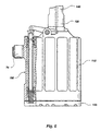
- Figure 2 is a cross-sectional view corresponding to the view in Figure 1, illustrating a nose assembly which is connectable to the tool of the present invention.
- Figure 3 is an enlarged view of a portion of the tool shown in Figure 1, further illustrating a slide valve.
- Figure 4 is a top view of the installation tool, further illustrating the slide valve, and also illustrating an air inlet swivel.
- Figure 5 is a cross-sectional view taken along line 5-5 of Figure 4, further illustrating the air inlet swivel.
- Figure 6 is a partial cross-sectional view illustrating a stable base of the installation tool, as well as a portion of a throttle of the tool.
- Suitable pintail fasteners include fasteners such as those described in United States Patent Nos. 5,049,016, 5,090,852, 5,125,778, and 5,171,115, issued to Nordyke, Dixon, Sadri, and McWilliams et al., respectively, and assigned to Huck International, Inc., as well as similar fasteners which have a deformable head disposed around a shaft and a pintail which is detachably secured to the shaft.
- Suitable workpieces may be formed of metal, composite materials, plastic, or any other rigid material.
- the tool 10 includes a nose piston cylinder 12 which surrounds a nose piston 14.
- the nose piston 14 has a nose end 16 and a tail end 18.
- the nose piston 14 also has a longitudinal bore 20 which connects a nose orifice 22 with a tail orifice 24.
- a spring 26 urges the nose piston 14 toward the nose end of the nose piston cylinder 12.
- a retaining nut 28 is threadable onto the nose end of the nose piston cylinder 12 for use in connecting the tool 10 to a nose assembly, such as the nose assembly indicated generally at 30 in Figure 2.
- a nose assembly must be connected to the tool 10 to permit use of the tool 10 in installing pintail fasteners.
- the nose assembly contains a set of jaws 32 disposed about an opening 34 of a passage 36.
- the jaws 32 are configured to grip annular grooves or locking rings of the type commonly found on the pintails of pintail fasteners (not shown).
- the nose assembly 30 also contains a collet 38, a spring 40, and other elements familiar to those of skill in the art.
- An engagement portion 42 of the nose assembly 30 is configured for releasable engagement with the nose end 16 of the nose piston 14.
- the retaining nut 28 is capable of being threaded onto the nose piston cylinder 12 over a flange 44 to secure the connection between the nose assembly 30 and the tool 10.
- the nose piston 14 also has a venturi bore 50 which meets the longitudinal bore 20 at a venturi orifice 52.
- the venturi bore 50 points generally toward the tail end 18 of the nose piston 14. That is, the venturi bore 50 is oriented at an acute angle with respect to the portion of the longitudinal bore 20 that is located between the nose orifice 22 ( Figure 1) and the venturi orifice 52.
- a single venturi bore 50 is illustrated, alternative embodiments include a plurality of venturi bores spaced apart about the nose piston 14.
- the tool 10 also includes a slide valve, which is indicated generally at 56.
- the slide valve 56 preferably includes a ring 58 which is positioned around the exterior of the nose piston cylinder 12.
- the outer surface of the ring 58 is equipped with ridges 60 to enable the user to easily grasp the ring 58 and slide it along the nose piston cylinder 12.
- a plate shaped like a portion of the ring is used in place of the ring.
- the inner portion of the plate is shaped to conform to the outer portion of the nose piston cylinder along which the plate slides.
- the outer surface of the plate is equipped with ridges, knurls, or other projections to aid users in grasping and sliding the plate by hand.
- the ring 58 is slidable between the open position illustrated in Figure 3, and one or more closed positions.
- a recess 62 on the inner surface of the ring 58 adjacent the nose piston cylinder 12 is in substantial fluid communication with at least one passage 64 through the cylinder 12.
- the passage 64 is in permanent fluid communication with an annular recess 66 inside the cylinder 12 adjacent the nose piston 14.
- the annular recess 66 in turn is in fluid communication with the venturi bore 50.
- O-rings 68 are positioned between the ring 58 and the cylinder 12 as fluid seals.
- the closed position of the ring 58 is a position in which the recess 62 is no longer in substantial fluid communication with the passage 64.
- the tool 10 is connectable to a conventional pressurized air hose (not shown) at an air feed which is indicated generally at 70.
- the air feed 70 includes a hose connector 72 which is in fluid communication with an air inlet swivel 74.
- the hose connector 72 is connectable to the conventional air hose.
- the hose connector 72 is secured to a swivel ring 76 which is preferably rotatable through 360 degrees or more about a swivel bolt 78.
- Rotation of the swivel ring 76, and hence of the hose connector 72, allows a hose connected to the connector 72 to hang generally downward as the tool 10 is positioned by the user, thereby reducing the amount of hose the user must lift to position the tool 10.
- the swivel bolt 78 is threaded into a mount 80 which extends from the tool 10.
- a passage 82 in the hose connector 72 communicates with an annular chamber 84 in the swivel bolt 78.
- the annular chamber 84 communicates with a second passage 86 which leads to a chamber 88.
- O-rings 90 are placed between the swivel bolt 78 and the swivel ring 76 as fluid seals.
- a flexible tube 92 provides fluid communication between the chamber 88 and the recess 62 on the inner surface of the slide valve ring 58.
- the tube 92 is in fluid communication at one end with an inlet 94 and at the other end with an outlet 96.
- the inlet 94 is in fluid communication with the chamber 88.
- the outlet 96 which is formed in the ring 58, is in fluid communication with the recess 62.
- a pintail container 100 is secured to the nose piston cylinder 12 about the tail orifice 24 of the longitudinal bore 20.
- the pintail container 100 includes an inner bottle 102 and an outer bottle 104 which are rotatable relative to one another.
- Each of the bottles 102, 104 has an opening 108 in its side.
- pintails may be removed from the container by rotating the bottles 102, 104 until the openings 108 align and then dropping the pintails through the openings 108.
- the openings 108 are preferably slot-shaped, but those of skill in the art will appreciate that substantially circular, triangular, or square openings, as well as opening of other shapes, may be used in alternative embodiments.
- the outer bottle 104 has longitudinal protruding ribs 106 ( Figure 4) around its side.
- the ribs 106 are preferably spaced about 30 degrees apart around the outer bottle 104.
- Those of skill in the art will appreciate that differently spaced ribs, knurls, or a slip-resistant material such as rubber may also be positioned around the outer bottle 104 to enhance the user's ability to grasp the bottle 104 and rotate it by hand.
- the tool 10 also includes an assembly, generally indicated at 110, for pressurizing the nose piston cylinder 12.
- the pressurizing assembly 110 includes an air cylinder 112 in which a piston head 114 is disposed.
- the piston head 114 divides the air cylinder 112 into a variably-sized drive chamber 116 and a corresponding variably-sized release chamber 118.
- the size of one of the chambers 116, 118 grows, and the size of the other of the chambers 116, 118 shrinks, as the piston head 114 slides within the air cylinder 112.
- a hydraulic cylinder 120 defines a hydraulic chamber 122 containing an incompressible hydraulic fluid.
- the hydraulic chamber 122 is positioned adjacent the air cylinder 112.
- the hydraulic chamber 122 is separated from the drive chamber 118 by a conventional gland assembly 124.
- a piston rod 126 which is rigidly secured to the piston head 114 slides within the hydraulic chamber 122 as the piston head 114 slides within the air cylinder 112.
- the hydraulic chamber 122 is in fluid communication with a nose piston cylinder hydraulic chamber 128 inside the nose piston cylinder 12.
- a dampening valve 130 allows gradual movement of hydraulic fluid from the hydraulic chamber 122 to the nose piston cylinder chamber 128 while inhibiting rapid fluid movement in the opposite direction.
- the exterior of the hydraulic cylinder 120 serves as a hand grip 140 or handle for the user.
- the hydraulic cylinder 120 is oriented at an angle ⁇ in the range from about 10 degrees to about 20 degrees away from a right angle with respect to the longitudinal axis of the nose piston cylinder 12.
- the angle ⁇ thus lies within the range of positions taken naturally by a user's hand with respect to their forearm.
- the centerline of a typical user's grip is typically several degrees away from a right angle. That is, if a user grips a straight rod in a natural way and with no forces acting on the rod other than the user's grip and gravity, the rod will typically be held at an angle from about 10 to about 20 degrees away from a right angle with respect to the user's forearm.
- the nose piston cylinder 12 and the user's forearm can each be held perpendicular to the workpieces (not shown) without forcing the user's wrist into an uncomfortable position.
- the air cylinder 112 is in fluid communication with a throttle, which is generally indicated at 150.
- the throttle 150 is connectable to a conventional pressurized air hose (not shown) by way of the air inlet swivel 74.
- the throttle 150 includes a trigger 152 for selective pressurization of the drive chamber 116 of the air cylinder 112.
- the air cylinder 112 is also in fluid communication with an exhaust path which leads from the drive chamber 116 to the ambient environment outside the tool.
- a muffler 154 disposed along the exhaust path muffles the flow of air exhausted from the drive chamber 116, making the tool 10 quieter during use than unmuffled conventional tools.
- the muffler 154 preferably comprises a wire mesh, but other embodiments include plastic formed in a mesh or a web.
- the weight of the nose piston 14 and the other components of the tool 10 is distributed such that the air cylinder 112 forms a stable base 156 for the tool 10.
- the base 156 has sufficient area, and is positioned relative to the tool's mass, to be capable of stable engagement with a resting surface such as a table or floor (not shown). That is, the tool 10 may be placed in a stable position on the resting surface with the nose piston cylinder 12 spaced substantially above the resting surface. In such a position, the tool's handle 140 is easily grasped by the user. Moreover, the risk of contaminating the nose assembly 30 (Figure 2) is greatly reduced because the nose assembly 30 is held above the work area floor by the air cylinder 112, the handle 140, and the nose piston cylinder 12.
- the pintail of a pintail fastener (not shown) is placed between the jaws 32 of the nose assembly 30 and a portion of the fastener is placed within aligned holes in two or more workpieces (not shown).
- the trigger 152 of the throttle 150 is activated by pressure of the user's finger, thereby allowing pressurized air to flow from an attached conventional air hose (not shown) through the air inlet swivel 74 ( Figure 5) into the drive chamber 116. Pressurization of the drive chamber 116 increases the size of the chamber 116 by driving the piston head 114 into the release chamber 118.
- the piston head 114 in turn drives the piston rod 126 toward the nose piston cylinder 12. In so moving, the piston rod 126 pressurizes the hydraulic fluid within the hydraulic chamber 122, and hence pressurizes the hydraulic fluid within the nose piston cylinder chamber 128.
- the increased pressure in the nose piston cylinder 12 urges the nose piston 14 away from its initial "ready” position and thus away from the workpieces (not shown).
- the nose piston 14 in turn creates an installation force which is transferred to the attached nose assembly 30.
- the installation force tightens the nose assembly jaws 32 about the pintail and pulls the pintail away from the workpieces in the direction indicated by Arrow A.
- the fastener's head deforms, and the fastener's pintail eventually detaches from the rest of the fastener.
- the nose piston 14 is in its "detaching" position, which may vary slightly from one fastener to the next.
- the nose piston 14 may move toward the nose assembly 30, in the direction opposite to that indicated by Arrow A. Movement of the piston 14 is dampened by the hydraulic fluid in the chambers 122, 128 because sudden flow of the hydraulic fluid back into the hydraulic chamber 122 is restricted by the dampening valve 130. The hydraulic fluid flowing from the nose piston cylinder hydraulic chamber 128 back into the handle's hydraulic cylinder 122 urges the piston rod 126 away from the nose piston cylinder 12, and hence moves the piston head 114 in a direction that decreases the size of the drive chamber 116.
- the throttle 150 is configured to open the exhaust path when the nose piston 14 reaches the detachment position, so the air from the drive chamber 116 flows out through the muffler 154 toward the ambient environment.
- the slide valve 56 If the slide valve 56 is in the open position (shown in Figure 3), the detached pintail will not remain in the longitudinal piston bore 20, but will rather be forced by the venturi effect into contact with a deflector (not shown) or the pintail container 100.
- a deflector not shown
- the slide valve 56 When the slide valve 56 is open and the nose piston 14 has returned to its initial position nearest the nose assembly 30, air flows through the venturi bore 50 ( Figure 3) under pressure. Air flowing through the venturi bore 50 into the longitudinal bore 20 creates the venturi effect.
- the venturi bore 50 is preferably positioned relative to the nose piston cylinder 12 such that the nose piston cylinder 12 blocks air flow to the venturi bore 50 as the nose piston 14 approaches the detaching position during installation, even if the slide valve 56 is open.
- the entire pressurized air flow from the air compressor is applied to the drive chamber 116 ( Figure 1) during installation.
- the venturi effect is created only when the nose piston 14 is near its ready position and the slide valve 56 is open.
- control of the venturi effect is not limited to this automatic control which is based on the nose piston's position.
- users may easily slide the ring 58 to close the slide valve 56, thereby conserving compressed air when the tool 10 is not in active use or when the tool 10 is in use but no venturi is needed to remove pintails from the nose assembly 30 ( Figure 2) and the nose piston 14.
- the pintail fastener installation tool of the present invention provides an easily-operated and flexible collector which utilizes a venturi effect to remove a pintail from the nose assembly and nose piston after the pintail is detached from a fastener.
- the slide valve is easily opened or closed with a single movement of the user's hand, rather than requiring multiple rotations and/or additional tools, as in conventional installation tools.
- the control is flexible in that the slide valve allows a user to override the automatic position-based venturi shut-off in order to further conserve compressed air.
- the tool of the present invention collects the detached pintails in an easily-emptied container rather than allowing them to hit the user or the work area floor.
- the ribbed outer bottle is easily rotated to align the bottle slots and allow the spent pintails to fall out into a disposal area.
- the tool facilitates proper positioning by reducing the stresses imposed on a user in several ways.
- the air inlet swivel allows the hose to hang generally straight downward.
- the handle is angled relative to the nose piston cylinder to ease stresses on the user's wrist.
- the exhaust path is muffled to ease noise which deters the user from approaching the tool sufficiently to position it correctly.
- the tool base also makes the tool easier to pick up, and reduces the risk of nose assembly contamination by positioning the nose assembly above the work area floor when the tool is set down.
Landscapes
- Engineering & Computer Science (AREA)
- Mechanical Engineering (AREA)
- Portable Nailing Machines And Staplers (AREA)
- Compressor (AREA)
Claims (18)
- Werkzeug (10) zum Installieren von Befestigungselementen in Werkstücken, wobei jedes Befestigungselement ein verformbares Element und ein lösbares Bolzenende aufweist und durch Aufbringung einer Installationskraft auf das Befestigungselement, die dieses verformt und das Bolzenende löst, installiert werden kann und wobei das Werkzeug an eine Naseneinheit (30) anschließbar ist, die so ausgebildet ist, daß sie eine Installationskraft aufbringt, mit
einem Nasenkolbenzylinder (12) ;
einem Nasenkolben (14), der gleitend im Nasenkolbenzylinder (12) angeordnet ist und ein Nasenende (16) sowie ein hinteres Ende (18) aufweist, wobei das Nasenende (16) des Nasenkolbens mit der Naseneinheit (30) verbindbar ist, der Nasenkolben (14) eine Längsbohrung (20) besitzt, die eine Nasenöffnung (22) im Nasenende (16) mit einer hinteren Öffnung (24) im hinteren Ende (18) verbindet, und der Nasenkolben (14) eine Venturi-Bohrung (50) aufweist, die die Längsbohrung (20) an einer Venturi-Öffnung (52) trifft, so daß die unter ausreichendem Druck durch die Venturi-Öffnung (52) strömende Luft einen Venturi-Effekt erzeugt, mit dem ein gelöstes Bolzenende zur hinteren Öffnung (24) und durch diese gezogen werden kann, wobei die Venturi-Bohrung (50) an einer Luftzuführung (70) an eine Quelle von unter Druck stehender Luft angeschlossen werden kann;
einem Gleitventil (56), das zwischen der Venturi-Bohrung (50) und der Luftzufühxung (70) angeordnet ist und zwischen einer offenen Position, in der unter Druck stehende Luft von der Luftzuführung (79) zur Venturi-Bohrung (50) strömen kann, und einer geschlossenen Position, in der ein Luftstrom von der Luftzuführung (70) zur Venturi-Bohrung (50) verhindert wird, linear gleitbar ist; und
Einrichtungen zum Unterdrucksetzen des Nasenkolbenzylinders (12). - Werkzeug nach Anspruch 1, bei dem das Gleitventil eine Außenfläche mit vorsprüngen aufweist, um die Gleitbewegung des Gleitventiles durch die Hand eines Benutzers zu erleichtern.
- Werkzeug nach Anspruch 1, bei dem die Venturi-Bohrung unter einem spitzen Winkel in bezug auf den Abschnitt der Längsbohrung zwischen der Nasenöffnung und der Venturi-Öffnung orientiert ist.
- Werkzeug nach Anspruch 1, bei dem die Venturi-Bohrung unter einem spitzen Winkel relativ zu dem Abschnitt der Längsbohrung zwischen der Nasenöffnung und der Venturi-Öffnung so orientiert ist, daß durch die Venturi-Öffnung unter ausreichendem Druck strömende Luft einen Venturi-Effekt erzeugt, mit dem ein gelöstes Bolzenende zur hinteren Öffnung hin und durch diese gezogen werden kann, wobei die Venturi-Bohrung an einer Luftzuführung mit einer Quelle von unter Druck stehender Luft verbindbar ist;
wobei das Gleitventil einen Ring (58) aufweist, der um das Äußere des Nasenkolbenzylinders (12) herum angeordnet ist und eine Ausnehmung (62) aufweist, die in wesentlicher Strömungsmittelverbindung mit der Luftzuführung steht und auf der Innenfläche des Gleitventiles (56) benachbart zum Nasenkolbenzylinder (12) angeordnet ist, wobei die Ausnehmung (62) in wesentlicher Strömungsmittelverbindung mit der Venturi-Öffnung steht, wenn sich das Gleitventil in der offenen Position befindet, und sich nicht in wesentlicher Strömungsmittelverbindung mit der Venturi-Öffnung befindet, wenn sich das Gleitventil in der geschlossenen Position befindet, und wobei der Ring eine Außenfläche mit Vorsgrüngen zur Erleichterung der Gleitbewegung des Gleitventiles durch die Hand eines Benutzers aufweist. - Werkzeug nach Anspruch 1, bei dem das Gleitventil eine Außenfläche mit Vorsprüngen zur Erleichterung der Gleitbewegung des Gleitventiles durch eine Hand eines Benutzers besitzt.
- Werkzeug nach Anspruch 1, bei dem das Gleitventil eine Ausnehmung aufweist, die in wesentlicher Strömungsmittelverbindung mit der Luftzuführung steht, auf einer Innenfläche des Gleitventiles benachbart zum Nasenkolbenzylinder angeordnet ist und in wesentlicher Strömungsmittelverbindung mit der Venturi-Öffnung steht, wenn sich das Gleitventil in der offenen Position befindet, sowie nicht in wesentlicher Strömungsmittelverbindung mit der Venturi-Borhung steht, wenn sich das Gleitventil in der geschlossenen Position befindet.
- Werkzeug nach einem der vorangehenden Ansprüche, bei dem das Gleitventil einen Ring umfaßt, der um das Äußere des Nasenkolbenzylinders herum angeordnet ist.
- Werkzeug nach einem der vorangehenden Ansprüche, bei dem das Ventil eine Ausnehmung aufweist, die in wesentlicher Strömungsmittelverbindung mit der Luftzuführung steht, auf einer Innenfläche des Gleitventiles benachbart zum Nasenkolbenzylinder angeordnet ist, in wesentlicher Strömungsmittelverbindung mit der Venturi-Öffnung steht, wenn sich das Gleitventil in der offenen Position befindet, und nicht in wesentlicher Strömungsmittelverbindung mit der Venturi-Bohrung steht, wenn sich das Gleitventil in der geschlossenen Position befindet.
- Werkzeug nach einem der vorangehenden Ansprüche, bei dem die Einrichtungen zum Unterdrucksetzen des Nasenkolbenzylinders umfassen:wobei der Hydraulikzylinder in Strömungsmittelverbindung mit dem Nasenkolbenzylinder steht, so daß bei Unterdrucksetzen der Antriebskammer die Kolbenstange angetrieben wird, bis sie ein Hydraulikmittel innerhalb des Hydraulikzylinders und somit innerhalb des Nasenkolbenzylinders unter Druck setzt, um auf diese Weise den Nasenkolben von den Werkstücken weg zu drücken und somit eine Installationskraft auf das Befestigungselement durch die Naseneinheit aufzubringen.einen Luftzylinder;einen Kolbenkopf, der gleitend im Luftzylinder angeordnet ist und diesen in eine Antriebskammer mit veränderlicher Größe sowie eine entsprechende Freigabekammer mit veränderlicher Größe unterteilt;einen Hydraulikzylinder, der benachbart zum Luftzylinder angeordnet und vom Luftzylinder über eine Stopfbüchseneinheit getrennt ist; undeine Kolbenstange, die am Kolbenkopf befestigt und gleitend im Hydraulikzylinder gelagert ist;
- Werkzeug nach Anspruch 9, das des weiteren ein Dämpfungsventil aufweist, das zwischen dem Hydraulikzylinder und dem Nasenkolbenzylinder angeordnet ist, um den plötzlichen Zustrom des Hydraulikmittels in Abhängigkeit vom Lösen eines Bolzenendes zu dämpfen.
- Werkzeug nach Anspruch 9 oder 10, das des weiteren eine Drossel umfaßt, die an eine Quelle von unter Druck stehender Luft anschließbar und in der Lage ist, selektiv betätigt zu werden, um die Antriebskammer des Luftzylinders unter Druck zu setzen.
- Werkzeug nach Anspruch 11, bei dem die Drossel eine Lufteinlaßdreheinrichtung umfaßt, die sich um 360° drehen kann, während sie unter Druck gesetzte Luft zur Antriebskammer fördert.
- Werkzeug nach einem der Ansprüche 9 bis 12, das des weiteren einen Schalldämpfer aufweist, der entlang einer Auslaßbahn zwischen der-Antriebskammer und der Umgebung außerhalb des Werkzeuges angeordnet ist und so ausgebildet ist, daß er in bezug auf einen von der Antriebskammer nach Aufbringung einer Installationskraft auf ein Befestigungselement abgegebenen Luftstrom eine Schalldämpfung bewirkt.
- Werkzeug nach einem der Ansprüche 9 bis 13, bei dem der Luftzylinder eine Basis bildet, die einen stabilen Eingriff mit einer Lagerfläche herbeiführen kann, so daß das Werkzeug in einer stabilen Position auf der Lagerfläche angeordnet werden kann, wobei sich der Nasenkolbenzylinder in einem wesentlichen Abstand von der Lagerfläche befindet.
- Werkzeug nach einem der vorangehenden Ansprüche, das des weiteren eine Ablenkeinrichtung für ein Bolzenende aufweist, die am Nasenkolbenzylinder um die hintere Öffnung der Längsbohrung herum befestigt ist, um abgetrennte Bolzenenden so abzulenken, daß sie sich unter einem Winkel zur Längsbohrung bewegen.
- Werkzeug nach einem der vorangehenden Ansprüche, das des weiteren einen Bolzenendenbehälter aufweist, der am Nasenkolbenzylinder um die hintere Öffnung der Längsbohrung herum angeordnet ist, um die abgetrennten Bolzenenden aufzunehmen.
- Werkzeug nach Anspruch 16, bei dem der Bolzenendenbehälter eine innere Flasche und eine äußere Flasche aufweist, die relativ zueinander drehbar sind, wobei jede Flasche einen Schlitz besitzt, die äußere Flasche eine Vielzahl von vorstehenden, beabstandeten Längsrippen aufweist und die Flaschen so ausgebildet sind, daß ein Bolzenende durch Drehen der Flaschen, bis die Schlitze ausgerichtet sind, und nachfolgendes Ausrichten des Bolzenendes mit den Schlitzen aus dem Behälter entfernt werden kann.
- Werkzeug nach einem der vorangehenden Ansprüche, bei dem die Venturi-Bohrung so im Nasenkolben angeordnet ist, daß bei einer Bewegung des Nasenkolbens im Nasenkolbenzylinder in einer Richtung zur Aufbringung der Installationskraft die Venturi-Bohrung in eine Position bewegt wird, in der der Nasenkolbenzylinder den Einlaß zur Venturi-Bohrung abdeckt, um zu verhindern, daß unter Druck stehende Luft durch die Venturi-Bohrung strömt.
Applications Claiming Priority (3)
| Application Number | Priority Date | Filing Date | Title |
|---|---|---|---|
| US302495 | 1994-09-08 | ||
| US08/302,495 US5490311A (en) | 1994-09-08 | 1994-09-08 | Ergonomic installation tool with selectable vacuum pintail collector |
| PCT/US1995/011328 WO1996007494A1 (en) | 1994-09-08 | 1995-09-07 | Installation tool with selectable pintail collector |
Publications (3)
| Publication Number | Publication Date |
|---|---|
| EP0804303A1 EP0804303A1 (de) | 1997-11-05 |
| EP0804303A4 EP0804303A4 (de) | 1998-02-25 |
| EP0804303B1 true EP0804303B1 (de) | 2003-01-02 |
Family
ID=23167969
Family Applications (1)
| Application Number | Title | Priority Date | Filing Date |
|---|---|---|---|
| EP95933743A Expired - Lifetime EP0804303B1 (de) | 1994-09-08 | 1995-09-07 | Installationswerkzeug mit auswählbarem dornsammler |
Country Status (6)
| Country | Link |
|---|---|
| US (1) | US5490311A (de) |
| EP (1) | EP0804303B1 (de) |
| JP (1) | JPH10505005A (de) |
| CA (1) | CA2199507C (de) |
| DE (1) | DE69529299T2 (de) |
| WO (1) | WO1996007494A1 (de) |
Families Citing this family (22)
| Publication number | Priority date | Publication date | Assignee | Title |
|---|---|---|---|---|
| DE29504316U1 (de) * | 1995-03-16 | 1995-04-27 | Maschinenbau Subotsch Verwaltungs- und Beteiligungsgesellschaft mbH, 65232 Taunusstein | Nietsetzwerkzeug |
| GB2301547A (en) * | 1995-06-02 | 1996-12-11 | Avdel Systems Ltd | Fastener installation tool |
| DE29822652U1 (de) * | 1998-12-22 | 2000-05-18 | MS Verwaltungs- und Patentgesellschaft mbH., 49084 Osnabrück | Nietwerkzeug |
| DE29900048U1 (de) * | 1999-01-06 | 2000-06-08 | MS Verwaltungs- und Patentgesellschaft mbH., 49084 Osnabrück | Nietsetzwerkzeug mit Drehumkehreinrichtung |
| US6519997B2 (en) | 2001-01-03 | 2003-02-18 | Allfast Fastening Systems, Inc. | Rivet gun |
| GB2394686B (en) * | 2001-02-21 | 2004-10-06 | Textron Fastening Syst Ltd | Fastener installation tool including fastener-parts collection means |
| PL200424B1 (pl) * | 2001-03-12 | 2009-01-30 | Gesipa Blindniettechnik | Nitownica do nitów jednostronnie zamykanych |
| US6425170B1 (en) * | 2001-06-04 | 2002-07-30 | Emhart Llc | Rivet setting tool with jaw guide and nose housing quick connect |
| US20060150402A1 (en) * | 2005-01-12 | 2006-07-13 | Yu-Ching Lin | Center position device of piston rod of riveter |
| US7082657B1 (en) * | 2005-02-17 | 2006-08-01 | Yu-Ching Lin | Automatic suction and repelling device for rivet gun |
| US7467451B2 (en) * | 2006-01-25 | 2008-12-23 | Sps Technologies, Llc | Offset pulling head |
| GB2442448B (en) * | 2006-10-03 | 2009-02-18 | Textron Fastening Syst Ltd | Improved stem collection containers for fastening tools |
| GB2447413B (en) * | 2007-03-16 | 2009-03-18 | Avdel Uk Ltd | Fastener installation tool |
| US9370820B2 (en) | 2007-03-16 | 2016-06-21 | Avdel Uk Limited | Fastener installation tool |
| GB2455730B (en) * | 2007-12-19 | 2009-12-23 | Avdel Uk Ltd | Fastener Installation Tool |
| US8615860B2 (en) | 2011-12-19 | 2013-12-31 | Sps Technologies, Llc | Jaw grip force adjustment system for offset and 90 degree pulling heads |
| US9316247B2 (en) * | 2013-01-18 | 2016-04-19 | Gage Bilt, Inc. | Feed mechanism for swagable lockbolt collars |
| US9511416B2 (en) | 2013-01-18 | 2016-12-06 | Gage Bilt, Inc. | Feed devices for swagable lockbolt collars |
| US9248494B2 (en) * | 2013-09-10 | 2016-02-02 | Yu-Tang Lin | Rivet gun having buffer device |
| US9586257B2 (en) | 2014-12-15 | 2017-03-07 | Gage Bilt, Inc. | Combination collar feeder and swaging tool |
| US11364579B2 (en) | 2018-10-12 | 2022-06-21 | Gage Bilt, Inc. | Feeder for swageable lockbolt collars and method of using same |
| US12042843B2 (en) * | 2019-10-10 | 2024-07-23 | Gage Bilt, Inc. | Fastener installation system with split tool head and actuation base |
Family Cites Families (22)
| Publication number | Priority date | Publication date | Assignee | Title |
|---|---|---|---|---|
| US3375883A (en) * | 1965-10-22 | 1968-04-02 | Gesipa Ges Fur Internationale | Electric hand riveting device |
| GB1479375A (en) * | 1974-05-25 | 1977-07-13 | Gesipa Blindentechnik Gmbh | Pneumatic-mechanical blind riveting tool |
| JPS5916538B2 (ja) * | 1974-08-30 | 1984-04-16 | ゲジパ プリントニ−トテヒニ−ク ゲゼルシヤフト ミツト ベシユレンクテル ハフツング | 盲鋲の自動鋲打方法及び鋲打機 |
| GB2025295B (en) * | 1978-06-24 | 1982-05-12 | Gesipa Blindniettechnik | Apparatus for collectingbroken-off mandrels of blind rivets |
| US4351179A (en) * | 1978-08-04 | 1982-09-28 | Gesipa Blindniettechnik Gesellschaft Mit Beschrankter Haftung | Manual riveting tool |
| US4275583A (en) * | 1979-04-20 | 1981-06-30 | Terence Gilbert | Breakstem riveting tool with stem disposal device |
| DE3112711C2 (de) * | 1981-03-31 | 1984-11-08 | Gesipa Blindniettechnik Gmbh, 6000 Frankfurt | Pneumatisch-hydraulisches Blindnietgerät |
| GB2116102A (en) * | 1982-03-08 | 1983-09-21 | Avdel Ltd | Riveting tool |
| DE3306827C2 (de) * | 1983-02-26 | 1986-05-07 | Gesipa Blindniettechnik Gmbh, 6000 Frankfurt | Pneumatisch-hydraulisches Setzgerät für Blindnietmuttern |
| US4517820A (en) * | 1983-06-22 | 1985-05-21 | Usm Corporation | Blind rivet tool |
| US4598571A (en) * | 1984-04-02 | 1986-07-08 | Usm Corporation | Control valve for a mandrel collection system |
| DE3664579D1 (en) * | 1985-05-10 | 1989-08-31 | Avdel Systems Ltd | Breakstem fastener installation tool |
| DE3532932A1 (de) * | 1985-09-14 | 1987-03-19 | Schwab Maschbau | Nietsetzwerkzeug |
| EP0302128B1 (de) * | 1987-08-04 | 1992-01-02 | Maschinenbau Subotsch & Schwab Gmbh | Nietsetzwerkzeug zum Setzen von Blindnieten |
| US4887450A (en) * | 1988-03-31 | 1989-12-19 | Textron, Inc. | Fastener stem collection apparatus and method |
| US4989442A (en) * | 1988-10-19 | 1991-02-05 | Huck Manufacturing Company | Nose assembly for pulling fasteners through interference fit holes |
| US4964292A (en) * | 1988-12-16 | 1990-10-23 | Huck Manufacturing Company | Shock-absorbing fluid-actuated pressure system |
| US4888974A (en) * | 1989-02-02 | 1989-12-26 | Emhart Industries, Inc. | Control valve for a mandrel collection system |
| US4896522A (en) * | 1989-03-21 | 1990-01-30 | Huck Manufacturing Company | Rotatable coupling for fastener installation tool |
| US5142774A (en) * | 1991-05-30 | 1992-09-01 | Huck Manufacturing Co. | Apparatus and method for loading fastener collars onto a mandrel |
| US5119554A (en) * | 1991-06-25 | 1992-06-09 | Huck Manufacturing Company | Pintail ejector assembly for fastener installation tooling |
| US5146773A (en) * | 1991-07-19 | 1992-09-15 | Huck Manufacturing Co. | Tapered rotatable offset nose assembly |
-
1994
- 1994-09-08 US US08/302,495 patent/US5490311A/en not_active Expired - Lifetime
-
1995
- 1995-09-07 WO PCT/US1995/011328 patent/WO1996007494A1/en not_active Ceased
- 1995-09-07 EP EP95933743A patent/EP0804303B1/de not_active Expired - Lifetime
- 1995-09-07 CA CA002199507A patent/CA2199507C/en not_active Expired - Lifetime
- 1995-09-07 JP JP8509659A patent/JPH10505005A/ja active Pending
- 1995-09-07 DE DE69529299T patent/DE69529299T2/de not_active Expired - Lifetime
Also Published As
| Publication number | Publication date |
|---|---|
| US5490311A (en) | 1996-02-13 |
| CA2199507A1 (en) | 1996-03-14 |
| EP0804303A1 (de) | 1997-11-05 |
| WO1996007494A1 (en) | 1996-03-14 |
| DE69529299T2 (de) | 2003-07-31 |
| DE69529299D1 (de) | 2003-02-06 |
| EP0804303A4 (de) | 1998-02-25 |
| JPH10505005A (ja) | 1998-05-19 |
| CA2199507C (en) | 2006-11-14 |
Similar Documents
| Publication | Publication Date | Title |
|---|---|---|
| EP0804303B1 (de) | Installationswerkzeug mit auswählbarem dornsammler | |
| EP0724505B1 (de) | Werkzeug zum herausziehen von ringförmigen einsätzen | |
| CA2080859A1 (en) | Pneumatically driven reverse impact device | |
| KR100843291B1 (ko) | 스웨이지 타입의 나사 화스너 설치용 설치 도구 | |
| US4887450A (en) | Fastener stem collection apparatus and method | |
| US11772117B2 (en) | Spray gun for spraying paints and other coatings | |
| EP0995518A2 (de) | Steuerung des Arbeitszyklus eines Nietwerkzeuges | |
| US7073989B2 (en) | Re-configurable bushing and drill incorporating same | |
| US6125680A (en) | Rivet tool adjustable rivet delivery device | |
| CA1266031A (en) | Breakstem fastener installation tool | |
| US6079604A (en) | Rivet tool escapement mechanism | |
| DE2603784A1 (de) | Sicherheitslufteinlass-ventilsteuerung fuer ein druckluftbetriebenes handwerkzeug | |
| JPH06102242B2 (ja) | オフセット工具およびカ−トリッジ型先端部組立体 | |
| US5469610A (en) | Fastening tool and fastener | |
| GB2025295A (en) | Apparatus for collectingbroken-off mandrels of blind rivets | |
| US6386532B1 (en) | Clamp squeeze apparatus and method | |
| US6418599B2 (en) | Setting apparatus for blind rivets or the like | |
| EP0995517B1 (de) | Nietwerkzeug mit luftunterstütztem Schnellruckhub | |
| US5406685A (en) | Pulling tool for extracting ring inserts | |
| US5647209A (en) | Fastener installation tool with positive pressure pintail removal system | |
| EP0468717A1 (de) | Blindnietgerät | |
| CN100531958C (zh) | 用于安装空心紧固件的紧固件安装工具 | |
| CN111906724B (zh) | 一种气动由壬拆装机 | |
| JPH11138230A (ja) | リベット締め装置 |
Legal Events
| Date | Code | Title | Description |
|---|---|---|---|
| PUAI | Public reference made under article 153(3) epc to a published international application that has entered the european phase |
Free format text: ORIGINAL CODE: 0009012 |
|
| 17P | Request for examination filed |
Effective date: 19970325 |
|
| AK | Designated contracting states |
Kind code of ref document: A1 Designated state(s): DE FR GB IT |
|
| A4 | Supplementary search report drawn up and despatched |
Effective date: 19980108 |
|
| AK | Designated contracting states |
Kind code of ref document: A4 Designated state(s): DE FR GB IT |
|
| 17Q | First examination report despatched |
Effective date: 20010216 |
|
| GRAG | Despatch of communication of intention to grant |
Free format text: ORIGINAL CODE: EPIDOS AGRA |
|
| RIN1 | Information on inventor provided before grant (corrected) |
Inventor name: ROSIER, HENDRIK, E. |
|
| RAP1 | Party data changed (applicant data changed or rights of an application transferred) |
Owner name: HUCK INTERNATIONAL, INC. |
|
| GRAG | Despatch of communication of intention to grant |
Free format text: ORIGINAL CODE: EPIDOS AGRA |
|
| GRAG | Despatch of communication of intention to grant |
Free format text: ORIGINAL CODE: EPIDOS AGRA |
|
| GRAH | Despatch of communication of intention to grant a patent |
Free format text: ORIGINAL CODE: EPIDOS IGRA |
|
| GRAH | Despatch of communication of intention to grant a patent |
Free format text: ORIGINAL CODE: EPIDOS IGRA |
|
| GRAA | (expected) grant |
Free format text: ORIGINAL CODE: 0009210 |
|
| AK | Designated contracting states |
Kind code of ref document: B1 Designated state(s): DE FR GB IT |
|
| REG | Reference to a national code |
Ref country code: GB Ref legal event code: FG4D Free format text: 20030102 |
|
| REF | Corresponds to: |
Ref document number: 69529299 Country of ref document: DE Date of ref document: 20030206 Kind code of ref document: P |
|
| ET | Fr: translation filed | ||
| PLBE | No opposition filed within time limit |
Free format text: ORIGINAL CODE: 0009261 |
|
| STAA | Information on the status of an ep patent application or granted ep patent |
Free format text: STATUS: NO OPPOSITION FILED WITHIN TIME LIMIT |
|
| 26N | No opposition filed |
Effective date: 20031003 |
|
| PGFP | Annual fee paid to national office [announced via postgrant information from national office to epo] |
Ref country code: DE Payment date: 20140922 Year of fee payment: 20 |
|
| PGFP | Annual fee paid to national office [announced via postgrant information from national office to epo] |
Ref country code: GB Payment date: 20140919 Year of fee payment: 20 Ref country code: FR Payment date: 20140919 Year of fee payment: 20 |
|
| PGFP | Annual fee paid to national office [announced via postgrant information from national office to epo] |
Ref country code: IT Payment date: 20140929 Year of fee payment: 20 |
|
| REG | Reference to a national code |
Ref country code: DE Ref legal event code: R071 Ref document number: 69529299 Country of ref document: DE |
|
| REG | Reference to a national code |
Ref country code: GB Ref legal event code: PE20 Expiry date: 20150906 |
|
| PG25 | Lapsed in a contracting state [announced via postgrant information from national office to epo] |
Ref country code: GB Free format text: LAPSE BECAUSE OF EXPIRATION OF PROTECTION Effective date: 20150906 |