EP0804282B1 - Verfahren und vorrichtung zur reinigung von gasen - Google Patents
Verfahren und vorrichtung zur reinigung von gasen Download PDFInfo
- Publication number
- EP0804282B1 EP0804282B1 EP96900779A EP96900779A EP0804282B1 EP 0804282 B1 EP0804282 B1 EP 0804282B1 EP 96900779 A EP96900779 A EP 96900779A EP 96900779 A EP96900779 A EP 96900779A EP 0804282 B1 EP0804282 B1 EP 0804282B1
- Authority
- EP
- European Patent Office
- Prior art keywords
- gases
- casing
- heat exchange
- exchange medium
- combustion
- Prior art date
- Legal status (The legal status is an assumption and is not a legal conclusion. Google has not performed a legal analysis and makes no representation as to the accuracy of the status listed.)
- Expired - Lifetime
Links
- 239000007789 gas Substances 0.000 title abstract description 71
- 238000000034 method Methods 0.000 title description 13
- 238000002485 combustion reaction Methods 0.000 abstract description 22
- 238000000354 decomposition reaction Methods 0.000 abstract description 17
- 239000002245 particle Substances 0.000 abstract description 14
- 239000002912 waste gas Substances 0.000 abstract description 6
- 150000004645 aluminates Chemical class 0.000 abstract description 3
- 239000004927 clay Substances 0.000 abstract description 2
- 150000002894 organic compounds Chemical class 0.000 abstract 1
- 239000000126 substance Substances 0.000 abstract 1
- 239000000047 product Substances 0.000 description 7
- 239000004575 stone Substances 0.000 description 6
- 238000000746 purification Methods 0.000 description 4
- 239000007787 solid Substances 0.000 description 4
- 239000003463 adsorbent Substances 0.000 description 3
- 239000007795 chemical reaction product Substances 0.000 description 3
- 238000001035 drying Methods 0.000 description 3
- MWUXSHHQAYIFBG-UHFFFAOYSA-N nitrogen oxide Inorganic materials O=[N] MWUXSHHQAYIFBG-UHFFFAOYSA-N 0.000 description 3
- 238000005192 partition Methods 0.000 description 3
- 239000003054 catalyst Substances 0.000 description 2
- 238000004140 cleaning Methods 0.000 description 2
- 239000000446 fuel Substances 0.000 description 2
- 238000010438 heat treatment Methods 0.000 description 2
- 239000010815 organic waste Substances 0.000 description 2
- RYGMFSIKBFXOCR-UHFFFAOYSA-N Copper Chemical compound [Cu] RYGMFSIKBFXOCR-UHFFFAOYSA-N 0.000 description 1
- 238000010521 absorption reaction Methods 0.000 description 1
- 150000007824 aliphatic compounds Chemical class 0.000 description 1
- 150000001491 aromatic compounds Chemical class 0.000 description 1
- QVGXLLKOCUKJST-UHFFFAOYSA-N atomic oxygen Chemical compound [O] QVGXLLKOCUKJST-UHFFFAOYSA-N 0.000 description 1
- 230000015572 biosynthetic process Effects 0.000 description 1
- XFWJKVMFIVXPKK-UHFFFAOYSA-N calcium;oxido(oxo)alumane Chemical compound [Ca+2].[O-][Al]=O.[O-][Al]=O XFWJKVMFIVXPKK-UHFFFAOYSA-N 0.000 description 1
- 230000003197 catalytic effect Effects 0.000 description 1
- 238000006555 catalytic reaction Methods 0.000 description 1
- 239000000919 ceramic Substances 0.000 description 1
- 239000003153 chemical reaction reagent Substances 0.000 description 1
- 238000009833 condensation Methods 0.000 description 1
- 230000005494 condensation Effects 0.000 description 1
- 229910052802 copper Inorganic materials 0.000 description 1
- 239000010949 copper Substances 0.000 description 1
- 230000003247 decreasing effect Effects 0.000 description 1
- 239000008187 granular material Substances 0.000 description 1
- 238000002347 injection Methods 0.000 description 1
- 239000007924 injection Substances 0.000 description 1
- 229910052751 metal Inorganic materials 0.000 description 1
- 239000002184 metal Substances 0.000 description 1
- 150000002739 metals Chemical class 0.000 description 1
- 239000000203 mixture Substances 0.000 description 1
- 239000001301 oxygen Substances 0.000 description 1
- 229910052760 oxygen Inorganic materials 0.000 description 1
- 239000002244 precipitate Substances 0.000 description 1
- 238000001556 precipitation Methods 0.000 description 1
- 238000000197 pyrolysis Methods 0.000 description 1
- 239000002699 waste material Substances 0.000 description 1
Images

Classifications
-
- B—PERFORMING OPERATIONS; TRANSPORTING
- B01—PHYSICAL OR CHEMICAL PROCESSES OR APPARATUS IN GENERAL
- B01D—SEPARATION
- B01D53/00—Separation of gases or vapours; Recovering vapours of volatile solvents from gases; Chemical or biological purification of waste gases, e.g. engine exhaust gases, smoke, fumes, flue gases, aerosols
- B01D53/02—Separation of gases or vapours; Recovering vapours of volatile solvents from gases; Chemical or biological purification of waste gases, e.g. engine exhaust gases, smoke, fumes, flue gases, aerosols by adsorption, e.g. preparative gas chromatography
- B01D53/04—Separation of gases or vapours; Recovering vapours of volatile solvents from gases; Chemical or biological purification of waste gases, e.g. engine exhaust gases, smoke, fumes, flue gases, aerosols by adsorption, e.g. preparative gas chromatography with stationary adsorbents
- B01D53/0407—Constructional details of adsorbing systems
- B01D53/0438—Cooling or heating systems
-
- B—PERFORMING OPERATIONS; TRANSPORTING
- B01—PHYSICAL OR CHEMICAL PROCESSES OR APPARATUS IN GENERAL
- B01D—SEPARATION
- B01D53/00—Separation of gases or vapours; Recovering vapours of volatile solvents from gases; Chemical or biological purification of waste gases, e.g. engine exhaust gases, smoke, fumes, flue gases, aerosols
- B01D53/02—Separation of gases or vapours; Recovering vapours of volatile solvents from gases; Chemical or biological purification of waste gases, e.g. engine exhaust gases, smoke, fumes, flue gases, aerosols by adsorption, e.g. preparative gas chromatography
- B01D53/06—Separation of gases or vapours; Recovering vapours of volatile solvents from gases; Chemical or biological purification of waste gases, e.g. engine exhaust gases, smoke, fumes, flue gases, aerosols by adsorption, e.g. preparative gas chromatography with moving adsorbents, e.g. rotating beds
- B01D53/08—Separation of gases or vapours; Recovering vapours of volatile solvents from gases; Chemical or biological purification of waste gases, e.g. engine exhaust gases, smoke, fumes, flue gases, aerosols by adsorption, e.g. preparative gas chromatography with moving adsorbents, e.g. rotating beds according to the "moving bed" method
-
- B—PERFORMING OPERATIONS; TRANSPORTING
- B01—PHYSICAL OR CHEMICAL PROCESSES OR APPARATUS IN GENERAL
- B01J—CHEMICAL OR PHYSICAL PROCESSES, e.g. CATALYSIS OR COLLOID CHEMISTRY; THEIR RELEVANT APPARATUS
- B01J8/00—Chemical or physical processes in general, conducted in the presence of fluids and solid particles; Apparatus for such processes
- B01J8/08—Chemical or physical processes in general, conducted in the presence of fluids and solid particles; Apparatus for such processes with moving particles
- B01J8/12—Chemical or physical processes in general, conducted in the presence of fluids and solid particles; Apparatus for such processes with moving particles moved by gravity in a downward flow
- B01J8/125—Chemical or physical processes in general, conducted in the presence of fluids and solid particles; Apparatus for such processes with moving particles moved by gravity in a downward flow with multiple sections one above the other separated by distribution aids, e.g. reaction and regeneration sections
-
- B—PERFORMING OPERATIONS; TRANSPORTING
- B01—PHYSICAL OR CHEMICAL PROCESSES OR APPARATUS IN GENERAL
- B01D—SEPARATION
- B01D2251/00—Reactants
- B01D2251/40—Alkaline earth metal or magnesium compounds
- B01D2251/404—Alkaline earth metal or magnesium compounds of calcium
-
- B—PERFORMING OPERATIONS; TRANSPORTING
- B01—PHYSICAL OR CHEMICAL PROCESSES OR APPARATUS IN GENERAL
- B01D—SEPARATION
- B01D2253/00—Adsorbents used in seperation treatment of gases and vapours
- B01D2253/10—Inorganic adsorbents
- B01D2253/104—Alumina
-
- B—PERFORMING OPERATIONS; TRANSPORTING
- B01—PHYSICAL OR CHEMICAL PROCESSES OR APPARATUS IN GENERAL
- B01D—SEPARATION
- B01D2253/00—Adsorbents used in seperation treatment of gases and vapours
- B01D2253/10—Inorganic adsorbents
- B01D2253/106—Silica or silicates
- B01D2253/11—Clays
-
- B—PERFORMING OPERATIONS; TRANSPORTING
- B01—PHYSICAL OR CHEMICAL PROCESSES OR APPARATUS IN GENERAL
- B01D—SEPARATION
- B01D2253/00—Adsorbents used in seperation treatment of gases and vapours
- B01D2253/25—Coated, impregnated or composite adsorbents
-
- B—PERFORMING OPERATIONS; TRANSPORTING
- B01—PHYSICAL OR CHEMICAL PROCESSES OR APPARATUS IN GENERAL
- B01D—SEPARATION
- B01D2257/00—Components to be removed
- B01D2257/70—Organic compounds not provided for in groups B01D2257/00 - B01D2257/602
- B01D2257/702—Hydrocarbons
- B01D2257/7022—Aliphatic hydrocarbons
-
- B—PERFORMING OPERATIONS; TRANSPORTING
- B01—PHYSICAL OR CHEMICAL PROCESSES OR APPARATUS IN GENERAL
- B01D—SEPARATION
- B01D2257/00—Components to be removed
- B01D2257/70—Organic compounds not provided for in groups B01D2257/00 - B01D2257/602
- B01D2257/702—Hydrocarbons
- B01D2257/7027—Aromatic hydrocarbons
-
- B—PERFORMING OPERATIONS; TRANSPORTING
- B01—PHYSICAL OR CHEMICAL PROCESSES OR APPARATUS IN GENERAL
- B01D—SEPARATION
- B01D2257/00—Components to be removed
- B01D2257/70—Organic compounds not provided for in groups B01D2257/00 - B01D2257/602
- B01D2257/708—Volatile organic compounds V.O.C.'s
-
- B—PERFORMING OPERATIONS; TRANSPORTING
- B01—PHYSICAL OR CHEMICAL PROCESSES OR APPARATUS IN GENERAL
- B01D—SEPARATION
- B01D2258/00—Sources of waste gases
- B01D2258/02—Other waste gases
- B01D2258/0283—Flue gases
-
- B—PERFORMING OPERATIONS; TRANSPORTING
- B01—PHYSICAL OR CHEMICAL PROCESSES OR APPARATUS IN GENERAL
- B01D—SEPARATION
- B01D2259/00—Type of treatment
- B01D2259/40—Further details for adsorption processes and devices
- B01D2259/40011—Methods relating to the process cycle in pressure or temperature swing adsorption
- B01D2259/40077—Direction of flow
- B01D2259/40081—Counter-current
-
- B—PERFORMING OPERATIONS; TRANSPORTING
- B01—PHYSICAL OR CHEMICAL PROCESSES OR APPARATUS IN GENERAL
- B01D—SEPARATION
- B01D2259/00—Type of treatment
- B01D2259/40—Further details for adsorption processes and devices
- B01D2259/40083—Regeneration of adsorbents in processes other than pressure or temperature swing adsorption
- B01D2259/40088—Regeneration of adsorbents in processes other than pressure or temperature swing adsorption by heating
- B01D2259/4009—Regeneration of adsorbents in processes other than pressure or temperature swing adsorption by heating using hot gas
Definitions
- the present invention concerns a method for purifying gases which contain thermally decomposable components, whereby these thermally decomposable components are thermally decomposed.
- thermally decomposable components are mainly understood volatile organic components which usually give off an unpleasant smell.
- volatile organic components are for example aromatic or aliphatic compounds.
- the invention concerns a method for decomposing thermally decomposable components, in particular volatile organic components which are present in gases, whereby these gases are led through a heat exchange medium consisting of particles which resist the decomposition temperature, and whereby these gases are heated in said heat exchange medium up to the decomposition temperature of the decomposable components.
- the gases may be derived from the drying and/or burning of organic waste and may largely consist of steam.
- the gases are carried downward by means of a stationary heat exchange medium consisting of ceramic rings, in which is erected an electrical heat resistor.
- the heat exchange medium is polluted relatively fast, so that it has to be replaced relatively quickly.
- the invention aims a method for decomposing thermally decomposable components which are present in gases, with an excellent heat exchange, whereby the heat exchanging mass has to be replaced less quickly and whereby this method can also be used for damp gases.
- the heat exchange medium is continuously carried around and consequently carried away from a first zone in which this heat exchange medium heats the gases and is again carried towards a second zone in which the heat exchange medium is heated, at least partly by the waste gases of the combustion of the decomposable components and/or of the decomposition products thereof and by the remainder of the gases which were further heated by this combustion, which combustion mainly takes place in a combustion zone situated between these zones.
- the heat exchange medium is an adsorbent which is mainly used for drying air in a topmost zone, whereas in a bottommost zone, the adsorbent is dried by other air which is heated by a burner.
- the adsorbent can be a catalyst, whereby a catalytic reaction in this case takes place in the topmost zone and whereby the catalyst is purified of adsorbed reagents and products in the bottommost zone.
- external calorific value is supplied to the combustion zone.
- the heat exchange medium is for example moved down through due to gravitation.
- the gases are preferably lead in a zigzag manner over the heat exchange medium, in such a manner that they cross said heat exchange medium several times.
- a suitable heat exchange medium is a granulated mass.
- the invention also concerns a device which is particularly suitable to carry out the method according to any of the above-described embodiments.
- the invention concerns a device for thermally decomposing thermally decomposable components which are present in gases, which device comprises a tower with three standing casings including an inner casing provided with openings which is closed at the bottom and at the top, a second casing provided with openings erected around this inner casing and an outer casing which surrounds this second casing, whereby the space between the second casing and the outer casing is divided in chambers which are situated on top of one another and which open into the space between the second casing and the inner casing via said openings in the second casing, and whereby the space inside the inner casing is divided in a top chamber and a bottom chamber; the device further comprising means to collect a medium, which consists of particles, at the bottom of the tower from the space between the inner casing and the second casing and to supply it back to the top of the tower between the inner casing and the second casing, and means to introduce the gases at the bottom through the second casing and to discharge the gases at the top through the second casing, said means comprising
- a device of this kind is known from US-A-2 636 575, although used for carrying out an absorption process.
- This device comprises three casings surrounding each other and particles between the the inner casing and a second casing, which inner and second casings are provided with openings.
- the inner and second casings of this device are not cilindrical but successivily decreasing in diameter and increasing in diameter.
- the standing casings are coaxial and cylindrical and the chambers in the space between the second casing and the outer casing are limited by walls between said second and outer casings, while the top chamber and the bottom chamber are separated by at least one partition dividing the space inside the inner casing, whereby the inlet for the gases opens into a chamber situated at the bottom between the second and outer casings and the exhaust for the gases opens into a chamber at the top between said second and outer casings.
- the device contains means to supply calorific value from outside to the gases between the inlet and the exhaust, either in the shape of hot gases or in the shape of injected fuel.
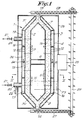
- the device for decomposing thermally decomposable components which are present in gases contains a tower 1 which mainly consists of three coaxial standing casings 2, 3 and 4 which form cylinders which are conically tapered on both ends.
- the inner casing 2 is closed at the top and at the bottom and is provided with openings 5 in its cylindrical part.
- the space inside this casing 2 is divided by partitions 6 in a top chamber 7 and a bottom chamber 8.
- this casing 2 can be made of hollow flame-resistant stones 9 which are provided with windows 10 in their bent walls which form the above-mentioned openings 5 together with the cavity 11 in the stones.
- the second, in other words the middlemost casing 3 is also provided with openings 12 in its cylindrical part and can be made of similar flame-resistant stones 9 in the same manner as the inner casing 2.
- the outer casing 4 is a solid wall of for example gas concrete.
- the conically tapered outer parts of these casings 3 and 4 are open at their end, such that at the top and at the bottom of the tower 1, they respectively form an inlet 13 and an exhaust 14 which open into the space 15 which is formed between the inner casing 2 and the second casing 3.
- the space between the second casing 3 and the outer casing 4 is divided by ring-shaped walls 16 in three ring-shaped chambers situated on top of one another, namely a bottom chamber 17, a middlemost chamber 18 and a topmost chamber 19.
- the second casing 3 is formed of hollow stones 9 at the place of a ring-shaped wall 16
- the hollow stone 9 is replaced by a solid stone in order to prevent that the chambers 17, 18 and 19 are directly connected to one another via the casing 3.
- the space between the inner casing 2 and the second casing 3 is not interrupted but filled with a heat exchange medium in the shape of a granulated mass consisting of particles which resist the temperatures required to dissolve the volatile organic components in the gases and which in particular resist temperatures of 800 to 900°C. For clarity's sake, this granulated mass is not represented in figure 3.
- Suitable particles are particles which easily absorb and give off heat such as burnt clay, aluminate, for example calcium aluminate or a composition containing aluminate.
- the gases which are derived from the drying and/or burning of organic waste, for example which are derived from a waste treatment unit, and which mainly consist of steam with volatile, thermally decomposable organic components which are usually harmful, can be supplied via an inlet 20 which opens into the bottom chamber 17 through the outer casing 4 by means of a fan 21 mounted in this inlet.
- a pipe 22 for supplying hot air to the gases.
- the gases are discharged from the top chamber 19 via an exhaust 23 which extends through the outer casing 4 and in which is also mounted a fan 21.
- Calorific value or heat can be supplied to the granulated mass by means of a ring-shaped gas pipe 24 which is erected in the middlemost chamber 18, which is provided with openings and is connected to an external burner 25 which is erected outside the outer casing 4.
- the outer casing 4 is further surrounded by a housing 26 through which the above-mentioned inlets 13 and 20 and the exhausts 14 and 23 extend.
- a discharge screw 27 Under the exhaust 14 for the granulated mass is erected a discharge screw 27 and above the inlet 13 for this granulated mass is erected a supply screw 28. In order to carry the granulated mass from one screw to the other, an elevator 29 is provided between the discharge screw 27 and the supply screw 28.
- a quantity of hot air is added to the gases via the pipe 22 to supply a sufficient amount of oxygen for the combustion of the thermally decomposable components and/or decomposition products thereof as well as air for the possible combustion of the gases injected via the gas pipe 24.
- This air preferably has a temperature of over 650°C, which also provides for a pre-heating of the gases, and, if these gases contain steam, lowers the saturation temperature of this steam and in this manner prevents condensation.
- the principle of the gas purification or in other words the decomposition of the decomposable components into harmless end products, consists in making the granulated mass circulate and leading the gases in counterflow in relation to a downward flow of this granulated mass, whereby the gases cross the flow of the granulated mass several times.
- the gases are blown in the bottommost zone 30 via the inlet 20 and the bottommost chamber 17 and through the second casing 3.
- the main part of these gases flows through the granulated mass and through the inner casing 2 in the bottommost chamber 8, whereby these gases are heated.
- the gases are stopped by a partition 6 and as a result again flow right through the zone 30 up to the middlemost chamber 18 between the casings 3 and 4, whereby they are further heated by the granulated mass.
- At least a part of the decomposable components usually already start to decompose into gaseous decomposition products which can be further thermally decomposed or burnt.
- combustion zone 32 In this middlemost chamber 18 and the part of the granulated mass connected to it via openings 12 in the second casing 3 is formed the combustion zone 32.
- the further decomposition of the decomposable components and/or decomposition products thereof takes place, and especially the combustion of the gaseous decomposition products into harmless end products, in particular CO 2 , H 2 and N 2 .
- the waste gases of the external burner 25 are possibly further burnt.
- the temperature of the gases rises in this combustion zone 32 with over 100°C, up to 800 to 900°C or even more.
- either ordinary heated gases or pure, for example gaseous fuel can be supplied via the gas pipe 24 instead of waste gases.
- the hot gases again radially flow through the granulated mass, namely the topmost zone 31 thereof, into the chamber 7, whereby the gases heat the granulated mass.
- the predominantly purified gases flow, opposite the exhaust 23, radially outward from the chamber 7 through the granulated mass, such that they further heat this granulated mass.
- the heat exchange between the granulated mass and the gases is excellent and the purification of the gases by means of decomposition or combustion of the thermally decomposable components can be carried out in a very economic manner.
- the granulated mass is self-cleaning to a large extent, it can be further cleaned outside the tower 1 during the circulation. During the purification, this granulated mass can be replaced in part or as a whole by new mass.
- the granulated mass can operate as a filter which stops the solid particles which may possibly be present in the gas flow, which preferably flows at a speed which is lower than 1.5 m/sec. During the cleaning of the granulated mass, these solid particles can then be removed via the discharge screw 27.
- Components such as metals which have been released during the purification, in particular copper, can precipitate on the particles of the granulated mass when it cools off. Thanks to the mutual friction of the particles as the granulated mass moves, this precipitation of the particles is removed.
- the method can be applied to damp gases, but these gases must not necessarily consist mainly of steam.
- the circulation of the granulated mass must not necessarily take place by means of an elevator. It can for example also take place by means of screws or such.
- the flow of the gases must not necessarily be caused by means of two fans. It can also be done with a single fan or with one or more extractors.
- Calorific value from outside the combustion zone is added as required. It is not excluded that, once the starting up is over, such addition is no longer required as the decomposition or combustion of the organic components in the gases provides sufficient heat to keep the decomposition going.
Landscapes
- Chemical & Material Sciences (AREA)
- Chemical Kinetics & Catalysis (AREA)
- Oil, Petroleum & Natural Gas (AREA)
- Engineering & Computer Science (AREA)
- Analytical Chemistry (AREA)
- General Chemical & Material Sciences (AREA)
- Organic Chemistry (AREA)
- Incineration Of Waste (AREA)
- Treating Waste Gases (AREA)
- Separation Using Semi-Permeable Membranes (AREA)
- Devices And Processes Conducted In The Presence Of Fluids And Solid Particles (AREA)
- Processing Of Solid Wastes (AREA)
- Gasification And Melting Of Waste (AREA)
- Exhaust Gas Treatment By Means Of Catalyst (AREA)
- Gas Separation By Absorption (AREA)
Claims (14)
- Verfahren zur Zerlegung von in Gasen vorhandenen thermisch zerlegbaren Bestandteilen, wobei diese Gase durch ein Wärmetauschmedium geleitet werden, das aus Partikeln besteht, die der Zerlegungstemperatur widerstehen, und wobei diese Gase in besagtem Wärmetauschmedium bis auf die Zerlegungstemperatur der zerlegbaren Bestandteile erhitzt werden, dadurch gekennzeichnet, daß man das Wärmetauschmedium kontinuierlich umlaufen läßt und es folglich von einer ersten Zone (30), worin dieses Wärmetauschmedium die Gase erhitzt, wiederum zu einer zweiten Zone (31) transportiert, worin das Wärmetauschmedium erhitzt wird, zumindest teilweise von den Abgasen der Verbrennung der flüchtigen organischen Bestandteile und/oder deren Zerlegungsprodukten, und von dem Rest der Gase, die durch diese Verbrennung weiter erhitzt wurden, welche Verbrennung hauptsächlich in einer Verbrennungszone (32) stattfindet, die sich zwischen diesen Zonen (30 und 31) befindet.
- Verfahren gemäß Anspruch 1, dadurch gekennzeichnet, daß die thermisch zerlegbaren Bestandteile in den Gasen flüchtige organische Bestandteile sind und daß die Gase in der Verbrennungszone (32) bis auf 800°C oder mehr erhitzt werden.
- Verfahren gemäß einem der Ansprüche 1 und 2, dadurch gekennzeichnet, daß, bevor die Gase die Verbrennungszone (32) erreichen, diesen Gasen Luft zugeführt wird.
- Verfahren gemäß Anspruch 3, dadurch gekennzeichnet, daß Luft mit einer Temperatur von über 650°C zugeführt wird.
- Verfahren gemäß Anspruch 3 oder 4, dadurch gekennzeichnet, daß den Gasen bis zu 10 Volumenprozent Luft zugesetzt werden.
- Verfahren gemäß einem der vorangehenden Ansprüche, dadurch gekennzeichnet, daß der Verbrennungszone (32) kalorische Leistung von außen zugesetzt wird.
- Verfahren gemäß einem der vorangehenden Ansprüche, dadurch gekennzeichnet, daß ein Überdruck von weniger als 5% im Verhältnis zum atmosphärischen Druck in der Verbrennungszone erzeugt wird.
- Verfahren gemäß einem der vorangehenden Ansprüche, dadurch gekennzeichnet, daß in der ersten und zweiten Zone (30 und 31) das Wärmetauschmedium aufgrund der Gravitation abwärtsbewegt wird und die Gase im Zickzack über das Wärmetauschmedium geleitet werden, so daß sie besagtes Wärmetauschmedium mehrere Male kreuzen.
- Verfahren gemäß einem der vorangehenden Ansprüche, dadurch gekennzeichnet, daß eine granulatförmige Masse als Wärmetauschmedium verwendet wird.
- Verfahren gemäß einem der vorangehenden Ansprüche, dadurch gekennzeichnet, daß eines der folgenden Materialien als granulatförmige Masse verwendet wird: Ton, Aluminat und eine Aluminat enthaltende Zusammensetzung.
- Vorrichtung zur thermischen Zerlegung thermisch zerlegbarer, in Gasen vorhandener Bestandteile, welche Vorrichtung einen Turm (1) mit drei aufrecht stehenden Ummantelungen (2, 3 und 4) umfaßt, einschließlich einer inneren, mit Öffnungen (5) versehenen Ummantelung (2), die an der Unterseite und der Oberseite geschlossen ist, einer zweiten, mit Öffnungen (12) versehenen Ummantelung (3), die um diese innere Ummantelung (2) angebracht ist, und einer Außenummantelung (4), die diese zweite Ummantelung (3) umgibt, wobei der Raum zwischen der zweiten Ummantelung (3) und der äußeren Ummantelung (4) in Kammern (17-18-19) aufgeteilt ist, die übereinander angeordnet sind und die über besagte Öffnungen (12) in der zweiten Ummantelung (3) in den Raum (15) zwischen der zweiten Ummantelung (3) und der inneren Ummantelung (2) münden, und wobei der Raum innerhalb der inneren Ummantelung (2) in eine obere Kammer (7) und eine untere Kammer (8) aufgeteilt ist; wobei die Vorrichtung weiter Mittel (27-28-29) umfaßt zum sammeln eines aus Partikeln bestehenden Mediums, an der Unterseite des Turms (1) aus dem Raum zwischen der inneren Ummantelung (2) und der zweiten Ummantelung (3), und zu dessen Rückführung zur Oberseite des Turms (1), zwischen der inneren Ummantelung (2) und der zweiten Ummantelung (3), und Mittel (20-21-23) zum Einspeisen der Gase an der Unterseite durch die zweite Ummantelung (3) und zum Abführen der Gase an der Oberseite durch die zweite Ummantelung (3), wobei besagte Mittel einen an der Unterseite befindlichen Einlaß (20) für die Gase und einen an der Oberseite befindlichen Abzug (23) für die Gase umfassen, dadurch gekennzeichnet, daß die aufrecht stehenden Ummantelungen (2-3-4) koaxial und zylindrisch sind und die Kammern (17-18-19) in dem Raum zwischen der zweiten Ummantelung (3) und der äußeren Ummantelung (4) durch Wände (16) zwischen besagten zweiten und äußeren Ummantelungen (3-4) eingegrenzt sind, während die obere Kammer (7) und die untere Kammer (8) durch zumindest eine Trennwand (6), die den Raum innerhalb der inneren Ummantelung (2) teilt, voneinander getrennt sind, wobei der Einlaß (20) für die Gase in eine Kammer (17) mündet, die sich unten zwischen der zweiten und der äußeren Ummantelung (3-4) befindet, und der Abzug für die Gase in eine Kammer (19) oben zwischen besagter zweiter und der äußeren Ummantelung (3-4) mündet.
- Vorrichtung gemäß Anspruch 11, dadurch gekennzeichnet, daß sie Mittel (24-25) umfaßt zur Zufuhr kalorischer Leistung von außen zu den Gasen, zwischen dem Einlaß (20) und dem Abzug (23) für die Gase.
- Vorrichtung gemäß Anspruch 12, dadurch gekennzeichnet, daß die Mittel (24-25) zur Zufuhr kalorischer Leistung zu den Gasen eine Gasleitung (24) umfassen, die in einer mittleren, zwischen der zweiten Ummantelung (3) und der äußeren Ummantelung (4) gebildeten Kammer (17) angebracht ist.
- Vorrichtung gemäß Anspruch 12 oder 13, dadurch gekennzeichnet, daß die Mittel (24-25) zur Zufuhr kalorischer Leistung zu den Gasen einen externen Brenner (25) außerhalb der äußeren Ummantelung (4) umfassen.
Applications Claiming Priority (3)
| Application Number | Priority Date | Filing Date | Title |
|---|---|---|---|
| BE9500034A BE1009045A3 (nl) | 1995-01-17 | 1995-01-17 | Werkwijze en inrichting voor het zuiveren van gassen. |
| BE9500034 | 1995-01-17 | ||
| PCT/BE1996/000004 WO1996022158A1 (en) | 1995-01-17 | 1996-01-16 | Method and device for purifying gases |
Publications (2)
| Publication Number | Publication Date |
|---|---|
| EP0804282A1 EP0804282A1 (de) | 1997-11-05 |
| EP0804282B1 true EP0804282B1 (de) | 1999-02-10 |
Family
ID=3888720
Family Applications (1)
| Application Number | Title | Priority Date | Filing Date |
|---|---|---|---|
| EP96900779A Expired - Lifetime EP0804282B1 (de) | 1995-01-17 | 1996-01-16 | Verfahren und vorrichtung zur reinigung von gasen |
Country Status (17)
| Country | Link |
|---|---|
| US (1) | US5885537A (de) |
| EP (1) | EP0804282B1 (de) |
| JP (1) | JPH11503062A (de) |
| CN (1) | CN1168108A (de) |
| AT (1) | ATE176603T1 (de) |
| BE (1) | BE1009045A3 (de) |
| BR (1) | BR9606762A (de) |
| CA (1) | CA2209799A1 (de) |
| CZ (1) | CZ210597A3 (de) |
| DE (1) | DE69601528T2 (de) |
| DK (1) | DK0804282T3 (de) |
| ES (1) | ES2130785T3 (de) |
| GR (1) | GR3030173T3 (de) |
| HU (1) | HUP9800629A3 (de) |
| PL (1) | PL321322A1 (de) |
| RU (1) | RU2152246C1 (de) |
| WO (1) | WO1996022158A1 (de) |
Families Citing this family (8)
| Publication number | Priority date | Publication date | Assignee | Title |
|---|---|---|---|---|
| DE19840358A1 (de) * | 1998-09-04 | 2000-03-09 | Motan Holding Gmbh | Verfahren zum Heizen und/oder Trocknen von fließfähigem Schüttgut, vorzugsweise von Kunststoffgranulat, und Heizeinrichtung zur Durchführung des Verfahrens |
| RU2170139C1 (ru) * | 1999-10-18 | 2001-07-10 | Рассадкин Юрий Павлович | Способ ускорения газофазных экзотермических реакций при низких температурах и устройство для его осуществления |
| US7317091B2 (en) * | 2002-03-01 | 2008-01-08 | Xencor, Inc. | Optimized Fc variants |
| DE102008026267A1 (de) * | 2008-06-02 | 2009-12-03 | Uhde Gmbh | Modifizierter Gas- und Dampfturbinenprozess mit integrierter Kohledruckvergasung |
| CN105013289B (zh) * | 2015-07-04 | 2017-03-29 | 上海煜工环保科技有限公司 | 均压移动床式活性焦吸附塔 |
| CN109772097B (zh) * | 2017-11-10 | 2020-07-03 | 中冶长天国际工程有限责任公司 | 活性炭法烟气净化装置及烟气净化方法 |
| CA3115721A1 (en) * | 2018-10-24 | 2020-04-30 | Stefan Bock | Method and apparatus for rapid and efficient heating of polymer pellets in preparation for processing in a plastifying means |
| CN116764372A (zh) * | 2021-12-27 | 2023-09-19 | 孙碧婷 | 一种高浓度氮氧化物三级尾气净化塔 |
Family Cites Families (15)
| Publication number | Priority date | Publication date | Assignee | Title |
|---|---|---|---|---|
| DE41572C (de) * | E. POHL in Betzdorf, Reg.-Bez. Koblenz | Ununterbrochen arbeitender Apparat zum Reinigen und Waschen von Gas | ||
| GB622112A (en) * | 1945-06-13 | 1949-04-27 | Babcock & Wilcox Co | Fluid heating apparatus |
| US2445554A (en) * | 1946-12-13 | 1948-07-20 | Socony Vacuum Oil Co Inc | Heater |
| US2636575A (en) * | 1947-08-20 | 1953-04-28 | Kenneth M Watson | Continuous adsorption process |
| GB677275A (en) * | 1949-11-23 | 1952-08-13 | Ernest Newell & Company Ltd | Improvements in or relating to kilns |
| NL6703522A (de) * | 1966-03-09 | 1967-09-11 | ||
| FR1528650A (fr) * | 1967-02-02 | 1968-06-14 | Commissariat Energie Atomique | échangeur thermique à accumulation sur lit mobile |
| US3987148A (en) * | 1974-09-19 | 1976-10-19 | Squires Arthur M | Treating gas and wetted granular material in panel bed |
| US4040794A (en) * | 1975-10-24 | 1977-08-09 | Uop Inc. | Moving bed contacting process and apparatus |
| JPS5268859A (en) * | 1975-12-08 | 1977-06-08 | Shokubai Kasei Kogyo Kk | Purifying method of gas containing combustible substance in low ceonce ntration |
| FR2486817B1 (fr) * | 1980-07-15 | 1985-11-08 | Tunzini Nessi Equip | Procede d'epuration des gaz et installation pour sa mise en oeuvre |
| JPS6080008A (ja) * | 1983-10-07 | 1985-05-07 | Agency Of Ind Science & Technol | 流動床燃焼装置 |
| FR2686347B1 (fr) * | 1992-01-22 | 1994-10-07 | Lorraine Carbone | Procede de pyrolyse d'effluents fluides et dispositif correspondant. |
| BE1008464A3 (nl) * | 1994-06-21 | 1996-05-07 | Groep Danis Nv | Werkwijze en inrichting voor het bewerken van afval met een kalorisch vermogen. |
| RU2091138C1 (ru) * | 1994-07-27 | 1997-09-27 | Новолипецкий металлургический комбинат | Устройство для очистки технологических газов |
-
1995
- 1995-01-17 BE BE9500034A patent/BE1009045A3/nl not_active IP Right Cessation
-
1996
- 1996-01-16 RU RU97113500/12A patent/RU2152246C1/ru active
- 1996-01-16 AT AT96900779T patent/ATE176603T1/de not_active IP Right Cessation
- 1996-01-16 JP JP8521924A patent/JPH11503062A/ja active Pending
- 1996-01-16 CN CN96191488A patent/CN1168108A/zh active Pending
- 1996-01-16 DE DE69601528T patent/DE69601528T2/de not_active Expired - Fee Related
- 1996-01-16 PL PL96321322A patent/PL321322A1/xx unknown
- 1996-01-16 CZ CZ972105A patent/CZ210597A3/cs unknown
- 1996-01-16 DK DK96900779T patent/DK0804282T3/da active
- 1996-01-16 US US08/860,921 patent/US5885537A/en not_active Expired - Fee Related
- 1996-01-16 BR BR9606762A patent/BR9606762A/pt not_active Application Discontinuation
- 1996-01-16 EP EP96900779A patent/EP0804282B1/de not_active Expired - Lifetime
- 1996-01-16 WO PCT/BE1996/000004 patent/WO1996022158A1/en not_active Ceased
- 1996-01-16 CA CA002209799A patent/CA2209799A1/en not_active Abandoned
- 1996-01-16 ES ES96900779T patent/ES2130785T3/es not_active Expired - Lifetime
- 1996-01-16 HU HU9800629A patent/HUP9800629A3/hu unknown
-
1999
- 1999-05-07 GR GR990401255T patent/GR3030173T3/el unknown
Also Published As
| Publication number | Publication date |
|---|---|
| ATE176603T1 (de) | 1999-02-15 |
| EP0804282A1 (de) | 1997-11-05 |
| JPH11503062A (ja) | 1999-03-23 |
| HUP9800629A3 (en) | 1998-12-28 |
| DE69601528D1 (de) | 1999-03-25 |
| ES2130785T3 (es) | 1999-07-01 |
| CN1168108A (zh) | 1997-12-17 |
| HUP9800629A2 (hu) | 1998-08-28 |
| CZ210597A3 (cs) | 1998-05-13 |
| BR9606762A (pt) | 1998-01-06 |
| DK0804282T3 (da) | 1999-09-20 |
| WO1996022158A1 (en) | 1996-07-25 |
| PL321322A1 (en) | 1997-12-08 |
| BE1009045A3 (nl) | 1996-11-05 |
| CA2209799A1 (en) | 1996-07-25 |
| RU2152246C1 (ru) | 2000-07-10 |
| GR3030173T3 (en) | 1999-08-31 |
| DE69601528T2 (de) | 1999-07-29 |
| US5885537A (en) | 1999-03-23 |
Similar Documents
| Publication | Publication Date | Title |
|---|---|---|
| CN100506953C (zh) | 固体燃料的气化装置 | |
| TW548384B (en) | Multifunctional disposal apparatus | |
| RU2002110816A (ru) | Способ газификации органических веществ и смесей веществ | |
| EP0804282B1 (de) | Verfahren und vorrichtung zur reinigung von gasen | |
| US4215637A (en) | System for combustion of wet waste materials | |
| EP0766721B1 (de) | Methode und vorrichtung zur verarbeitung von abwasser mit einem heizwert | |
| US5791267A (en) | Waste pyrolysis process and installation having a preheating unit | |
| JP4008414B2 (ja) | 無煙式多孔質炭の製造方法及びその製造装置 | |
| WO1990011473A1 (en) | Heating device | |
| JP3121840B2 (ja) | 熱処理すべき物質の処理法 | |
| HU208498B (en) | Method for catalytic firing organic compounds and catalytic firing apparatus for firing organic compounds | |
| US4052266A (en) | Method and apparatus for purifying process waste emissions | |
| GB2044901A (en) | Combustion method for removal of impurities from a gas | |
| WO1998010223A1 (en) | Incinerator | |
| US3612032A (en) | Muffle-type gas-fired self-cleaning oven | |
| RU97113500A (ru) | Способ и устройство для очистки газов | |
| GB2192978A (en) | Process for drying swarf or other small items contaminated with volatile substances | |
| RU98101334A (ru) | Способ переработки горючих твердых бытовых отходов | |
| KR102612476B1 (ko) | 유기성폐기물의 고효율 및 저에너지 소각, 연소, 탄화, 건조 시스템 | |
| KR100508766B1 (ko) | 소각장치 | |
| JP2025160057A (ja) | 加熱炉システム | |
| GB2209386A (en) | Thermal regenerators | |
| RU2175666C1 (ru) | Установка для производства древесного угля | |
| KR200177720Y1 (ko) | 육류숯불구이기의 순환공기정화장치 | |
| KR800001352B1 (ko) | 활성탄 재생장치 |
Legal Events
| Date | Code | Title | Description |
|---|---|---|---|
| PUAI | Public reference made under article 153(3) epc to a published international application that has entered the european phase |
Free format text: ORIGINAL CODE: 0009012 |
|
| 17P | Request for examination filed |
Effective date: 19970627 |
|
| AK | Designated contracting states |
Kind code of ref document: A1 Designated state(s): AT BE CH DE DK ES FR GB GR IE IT LI LU MC NL PT SE |
|
| 17Q | First examination report despatched |
Effective date: 19971112 |
|
| GRAG | Despatch of communication of intention to grant |
Free format text: ORIGINAL CODE: EPIDOS AGRA |
|
| GRAG | Despatch of communication of intention to grant |
Free format text: ORIGINAL CODE: EPIDOS AGRA |
|
| GRAH | Despatch of communication of intention to grant a patent |
Free format text: ORIGINAL CODE: EPIDOS IGRA |
|
| GRAH | Despatch of communication of intention to grant a patent |
Free format text: ORIGINAL CODE: EPIDOS IGRA |
|
| GRAA | (expected) grant |
Free format text: ORIGINAL CODE: 0009210 |
|
| AK | Designated contracting states |
Kind code of ref document: B1 Designated state(s): AT BE CH DE DK ES FR GB GR IE IT LI LU MC NL PT SE |
|
| REF | Corresponds to: |
Ref document number: 176603 Country of ref document: AT Date of ref document: 19990215 Kind code of ref document: T |
|
| REG | Reference to a national code |
Ref country code: CH Ref legal event code: EP |
|
| REG | Reference to a national code |
Ref country code: IE Ref legal event code: FG4D |
|
| REG | Reference to a national code |
Ref country code: CH Ref legal event code: NV Representative=s name: DIPL.-ING. ETH H. R. WERFFELI PATENTANWALT |
|
| REF | Corresponds to: |
Ref document number: 69601528 Country of ref document: DE Date of ref document: 19990325 |
|
| ET | Fr: translation filed | ||
| ITF | It: translation for a ep patent filed | ||
| REG | Reference to a national code |
Ref country code: PT Ref legal event code: SC4A Free format text: AVAILABILITY OF NATIONAL TRANSLATION Effective date: 19990405 |
|
| REG | Reference to a national code |
Ref country code: ES Ref legal event code: FG2A Ref document number: 2130785 Country of ref document: ES Kind code of ref document: T3 |
|
| REG | Reference to a national code |
Ref country code: DK Ref legal event code: T3 |
|
| PLBE | No opposition filed within time limit |
Free format text: ORIGINAL CODE: 0009261 |
|
| STAA | Information on the status of an ep patent application or granted ep patent |
Free format text: STATUS: NO OPPOSITION FILED WITHIN TIME LIMIT |
|
| PGFP | Annual fee paid to national office [announced via postgrant information from national office to epo] |
Ref country code: CH Payment date: 20000103 Year of fee payment: 5 |
|
| PGFP | Annual fee paid to national office [announced via postgrant information from national office to epo] |
Ref country code: LU Payment date: 20000104 Year of fee payment: 5 |
|
| PGFP | Annual fee paid to national office [announced via postgrant information from national office to epo] |
Ref country code: PT Payment date: 20000111 Year of fee payment: 5 |
|
| PGFP | Annual fee paid to national office [announced via postgrant information from national office to epo] |
Ref country code: IE Payment date: 20000112 Year of fee payment: 5 |
|
| PGFP | Annual fee paid to national office [announced via postgrant information from national office to epo] |
Ref country code: AT Payment date: 20000114 Year of fee payment: 5 |
|
| 26N | No opposition filed | ||
| PGFP | Annual fee paid to national office [announced via postgrant information from national office to epo] |
Ref country code: GR Payment date: 20000131 Year of fee payment: 5 |
|
| PGFP | Annual fee paid to national office [announced via postgrant information from national office to epo] |
Ref country code: MC Payment date: 20000310 Year of fee payment: 5 |
|
| PG25 | Lapsed in a contracting state [announced via postgrant information from national office to epo] |
Ref country code: LU Free format text: LAPSE BECAUSE OF NON-PAYMENT OF DUE FEES Effective date: 20010116 Ref country code: IE Free format text: LAPSE BECAUSE OF NON-PAYMENT OF DUE FEES Effective date: 20010116 Ref country code: AT Free format text: LAPSE BECAUSE OF NON-PAYMENT OF DUE FEES Effective date: 20010116 |
|
| PGFP | Annual fee paid to national office [announced via postgrant information from national office to epo] |
Ref country code: FR Payment date: 20010124 Year of fee payment: 6 |
|
| PGFP | Annual fee paid to national office [announced via postgrant information from national office to epo] |
Ref country code: NL Payment date: 20010129 Year of fee payment: 6 |
|
| PGFP | Annual fee paid to national office [announced via postgrant information from national office to epo] |
Ref country code: DK Payment date: 20010130 Year of fee payment: 6 |
|
| PG25 | Lapsed in a contracting state [announced via postgrant information from national office to epo] |
Ref country code: MC Free format text: LAPSE BECAUSE OF NON-PAYMENT OF DUE FEES Effective date: 20010131 Ref country code: LI Free format text: LAPSE BECAUSE OF NON-PAYMENT OF DUE FEES Effective date: 20010131 Ref country code: CH Free format text: LAPSE BECAUSE OF NON-PAYMENT OF DUE FEES Effective date: 20010131 |
|
| PGFP | Annual fee paid to national office [announced via postgrant information from national office to epo] |
Ref country code: SE Payment date: 20010131 Year of fee payment: 6 |
|
| PGFP | Annual fee paid to national office [announced via postgrant information from national office to epo] |
Ref country code: GB Payment date: 20010202 Year of fee payment: 6 |
|
| PGFP | Annual fee paid to national office [announced via postgrant information from national office to epo] |
Ref country code: ES Payment date: 20010215 Year of fee payment: 6 |
|
| PGFP | Annual fee paid to national office [announced via postgrant information from national office to epo] |
Ref country code: DE Payment date: 20010312 Year of fee payment: 6 |
|
| PG25 | Lapsed in a contracting state [announced via postgrant information from national office to epo] |
Ref country code: PT Free format text: LAPSE BECAUSE OF NON-PAYMENT OF DUE FEES Effective date: 20010731 |
|
| PG25 | Lapsed in a contracting state [announced via postgrant information from national office to epo] |
Ref country code: GR Free format text: LAPSE BECAUSE OF NON-PAYMENT OF DUE FEES Effective date: 20010806 |
|
| REG | Reference to a national code |
Ref country code: CH Ref legal event code: PL |
|
| REG | Reference to a national code |
Ref country code: IE Ref legal event code: MM4A |
|
| REG | Reference to a national code |
Ref country code: PT Ref legal event code: MM4A Free format text: LAPSE DUE TO NON-PAYMENT OF FEES Effective date: 20010731 |
|
| REG | Reference to a national code |
Ref country code: GB Ref legal event code: IF02 |
|
| PG25 | Lapsed in a contracting state [announced via postgrant information from national office to epo] |
Ref country code: GB Free format text: LAPSE BECAUSE OF NON-PAYMENT OF DUE FEES Effective date: 20020116 Ref country code: DK Free format text: LAPSE BECAUSE OF NON-PAYMENT OF DUE FEES Effective date: 20020116 |
|
| PG25 | Lapsed in a contracting state [announced via postgrant information from national office to epo] |
Ref country code: SE Free format text: LAPSE BECAUSE OF NON-PAYMENT OF DUE FEES Effective date: 20020117 Ref country code: ES Free format text: LAPSE BECAUSE OF NON-PAYMENT OF DUE FEES Effective date: 20020117 |
|
| PG25 | Lapsed in a contracting state [announced via postgrant information from national office to epo] |
Ref country code: NL Free format text: LAPSE BECAUSE OF NON-PAYMENT OF DUE FEES Effective date: 20020801 Ref country code: DE Free format text: LAPSE BECAUSE OF NON-PAYMENT OF DUE FEES Effective date: 20020801 |
|
| EUG | Se: european patent has lapsed |
Ref document number: 96900779.8 |
|
| GBPC | Gb: european patent ceased through non-payment of renewal fee |
Effective date: 20020116 |
|
| PG25 | Lapsed in a contracting state [announced via postgrant information from national office to epo] |
Ref country code: FR Free format text: LAPSE BECAUSE OF NON-PAYMENT OF DUE FEES Effective date: 20020930 |
|
| NLV4 | Nl: lapsed or anulled due to non-payment of the annual fee |
Effective date: 20020801 |
|
| REG | Reference to a national code |
Ref country code: FR Ref legal event code: ST |
|
| PGFP | Annual fee paid to national office [announced via postgrant information from national office to epo] |
Ref country code: BE Payment date: 20031117 Year of fee payment: 9 |
|
| PG25 | Lapsed in a contracting state [announced via postgrant information from national office to epo] |
Ref country code: IT Free format text: LAPSE BECAUSE OF NON-PAYMENT OF DUE FEES;WARNING: LAPSES OF ITALIAN PATENTS WITH EFFECTIVE DATE BEFORE 2007 MAY HAVE OCCURRED AT ANY TIME BEFORE 2007. THE CORRECT EFFECTIVE DATE MAY BE DIFFERENT FROM THE ONE RECORDED. Effective date: 20050116 |
|
| PG25 | Lapsed in a contracting state [announced via postgrant information from national office to epo] |
Ref country code: BE Free format text: LAPSE BECAUSE OF NON-PAYMENT OF DUE FEES Effective date: 20050131 |
|
| BERE | Be: lapsed |
Owner name: *DRUWEL NORBERT Effective date: 20050131 Owner name: GROEP *DANIS N.V. Effective date: 20050131 |
|
| BERE | Be: lapsed |
Owner name: *DRUWEL NORBERT Effective date: 20050131 Owner name: GROEP *DANIS N.V. Effective date: 20050131 |