EP0803837A2 - Méthode d'impression utilisant des motifs de surimposition - Google Patents
Méthode d'impression utilisant des motifs de surimposition Download PDFInfo
- Publication number
- EP0803837A2 EP0803837A2 EP96116705A EP96116705A EP0803837A2 EP 0803837 A2 EP0803837 A2 EP 0803837A2 EP 96116705 A EP96116705 A EP 96116705A EP 96116705 A EP96116705 A EP 96116705A EP 0803837 A2 EP0803837 A2 EP 0803837A2
- Authority
- EP
- European Patent Office
- Prior art keywords
- fill area
- overlay pattern
- pattern
- memory
- printed image
- Prior art date
- Legal status (The legal status is an assumption and is not a legal conclusion. Google has not performed a legal analysis and makes no representation as to the accuracy of the status listed.)
- Granted
Links
Images


Classifications
-
- G—PHYSICS
- G06—COMPUTING OR CALCULATING; COUNTING
- G06K—GRAPHICAL DATA READING; PRESENTATION OF DATA; RECORD CARRIERS; HANDLING RECORD CARRIERS
- G06K15/00—Arrangements for producing a permanent visual presentation of the output data, e.g. computer output printers
- G06K15/02—Arrangements for producing a permanent visual presentation of the output data, e.g. computer output printers using printers
-
- G—PHYSICS
- G06—COMPUTING OR CALCULATING; COUNTING
- G06K—GRAPHICAL DATA READING; PRESENTATION OF DATA; RECORD CARRIERS; HANDLING RECORD CARRIERS
- G06K2215/00—Arrangements for producing a permanent visual presentation of the output data
- G06K2215/0002—Handling the output data
- G06K2215/004—Generic data transformation
-
- G—PHYSICS
- G06—COMPUTING OR CALCULATING; COUNTING
- G06K—GRAPHICAL DATA READING; PRESENTATION OF DATA; RECORD CARRIERS; HANDLING RECORD CARRIERS
- G06K2215/00—Arrangements for producing a permanent visual presentation of the output data
- G06K2215/0002—Handling the output data
- G06K2215/0062—Handling the output data combining generic and host data, e.g. filling a raster
- G06K2215/0065—Page or partial page composition
Definitions
- This invention relates to digital printers, and more particularly, to a method of operating a digital printer to produce a printed image on a print medium.
- Digital printers are capable of producing full color images with high quality and precision. Such printers are controlled by a printer driver program which provides an interface between an application program running on a host processor and the printer.
- a pattern may be thought of as a background or a filler.
- a pattern is usually applied to a so-called object or source which appears as part of a printed image on a print medium.
- patterns are defined by a memory bit map which stores data which defines the "on" or "off” condition of a plurality of pixels forming a pattern.
- a memory bit map defining a pattern had to be pre-replicated across a width associated with the width of a page to be printed. This is because the location of a source or object to be patterned was not known.
- the entire memory bit map corresponding to that pattern had to span the entire physical page in width and span vertically a minimum of one pattern tile height.
- a pattern were one-half inch in height, for a 600 dot-per-inch (dpi) printer, roughly 300 lines would have to be replicated across the page, each line being around 6000 pixels in width.
- This pre-replicated bit map is also referred to as a pre-tiled pattern.
- pre-replicating a memory bit map corresponding to a pattern requires large amounts of memory.
- a memory bit map for a 48-pixel wide by 48-pixel high pattern would have to be expanded from 288 bytes to approximately 13 times that amount, or 4K.
- a pattern that was one-inch square would have to be expanded from 45K to about 370K.
- This invention arose out of a need to improve the manner in which digital printers produce printed pattern images and reduce the memory usage associated with the production of such patterned images.
- a method of operating a digital printer for producing a printed image on a print medium is described.
- the method is intended for use with a printer which includes at least one memory for holding an overlay pattern bit map which defines an overlay pattern at least portions of which are utilized in printing the printed image onto the print medium, and an image processor for processing image data used to produce the printed image.
- the method includes defining at least one fill area to be printed with at least a portion of the overlay pattern; reading at least a portion of the overlay pattern bit map from said memory; providing at least one boundary point which in part defines a fill area subset which serves to fill a portion of the fill area and define a portion of the printed image appearing therewithin; applying at least a portion of the overlay pattern bit map read from memory to the fill area subset; and writing the fill area subset to an output buffer which stores data defining at least a portion of the printed image.
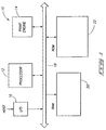
- Fig. 1 is a high level block diagram of a printer that is adapted to carry out the invention.
- Fig. 2 is a block diagram which illustrates one manner of carrying out the invented method.
- Fig. 3 is a high level flow diagram illustrating a preferred method of implementing the invention.
- Fig. 4 is a diagram which illustrates a pixel-by-pixel copy model which is used to illustrate the concept by which a preferred 32-bit word-copy model operates.
- Fig. 5 illustrates various definitional elements which are utilized in implementing the 32-bit word-copy model.
- Fig. 6 is a high level flow diagram which illustrates the 32-bit word-copy model.
- Fig. 7 is a flow diagram which sets forth a variable setup procedure.
- Fig. 8 is a flow diagram which sets forth the so-called s-d cases.
- Fig. 9 is a flow diagram which sets forth a so-called even-width carry case.
- Fig. 10 is a flow diagram which sets forth a so-called no-carry processing case.
- Fig. 11 is a flow diagram which sets forth a so-called carry processing case.
- digital printer 10 includes a processor 12, print engine 14, and an input/output (I/O) port 16, all connected by a bus 18.
- Print engine 14 comprises a laser printer which, when operated, runs at a constant speed and must be provided with video raster print data at a rate that keeps up with its operation.
- a random access memory (RAM) 20 and a read-only memory (ROM) 22 are also connected to bus 18, and contain procedures and other necessary data to operate the printer, and particularly print engine 14.
- RAM random access memory
- ROM read-only memory
- the present invention reduces printer memory consumption associated with the printing of a patterned image by determining where a particular pattern needs to appear, producing the correct amount of needed pattern, and then printing such pattern in a desired location on a print medium such as paper anchored to the page as specified by the user.
- anchor just used means a user-defined starting point. That is, this invention provides an added degree of flexibility insofar as a particular pattern or patterns could be anchored or pinned so-to-speak anywhere on a page as specified by the user. Subsequently, only needed portions of a pattern are produced and rendered onto the print medium. This completely eliminates the need to pre-replicate a pattern across the entire page as was done in the past, unless the elementary pattern tile width covers the entire page.
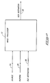
- Fig. 2 shows a simple block diagram which illustrates one manner in which the above advantage is achieved. More specifically, image processor 12 receives three inputs, a source 24, a pattern 26, and an old destination 28.
- Source 24 is an abstraction which provides boundary points for an object which is to appear as a printed image on a print medium. The source defines a so-called fill area which is to be filled in with a portion of an overlay pattern.
- Pattern 26 represents at least a portion of an overlay pattern bit map which defines an overlay pattern. The overlay pattern bit map may reside in the printer's memory and is capable of being read for producing a printed patterned image discussed in more detail below.
- Old destination 28 represents a so-called strip which is built by the printer and assists the printer in printing a printed image.
- a destination or strip defines a buffer for holding a plurality of bits which are used to modulate a laser for producing dark or light areas on a printed page as will be understood by those of skill in the art.
- Processor 12 operates upon source 24, pattern 26, and old destination 28 to define as an output a new destination 30.
- New destination 30 is an output buffer which stores data which is used by the printer for producing a portion of a printed image on the print medium.
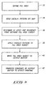
- Fig. 3 shows a high level block diagram illustrating a preferred method for implementing the current invention.
- the method includes, at step 32, defining at least one fill area which is to be printed with at least a portion of an overlay pattern.
- the fill area corresponds to source 24 of Fig. 2 as discussed above.
- a fill area may have any particular shape when it appears as part of a printed image on a print medium. Such shapes may includes ovals, ellipses, triangles, squares, rectangles or any other suitable shape described by a set of vectors that can adequately define the fill area for purposes of printer operation.
- the current typical fill area will be defined by a set of one or more vectors which form an enclosed area. Complex shapes with internal holes, such as donut shapes, are first decomposed into elementary geometric shapes without internal holes.
- the overlay pattern is defined by an overlay pattern bit map which is stored or held in a memory location such as RAM 20 or ROM 22 in printer 10.
- a portion of the overlay bit map pattern is read from memory.
- the portion of the overlay pattern bit map which is read is a single line out of the bit map, or at least a portion of a single line.
- the portion of a line which is read from the overlay pattern bit map comprises a multi-bit word which is preferably a 32-bit word.
- at least one boundary point, and preferably two are provided, which define a fill area subset.
- a fill area subset serves to fill a portion of a fill area (which could be and preferably is one horizontal line), and defines a portion of a printed image appearing therewithin.
- step 38 the portion of the overlay bit map which was read from memory is applied to the fill area subset.
- step 40 the fill area subset containing the applied portion of the overlay bit map is written to an output buffer, also referred to above as new destination 30, which stores data defining at least a portion of the printed image.
- step 42 the contents of the output buffer defined by step 40 are transferred to effect printing of a printed image. It will be understood that the step of transferring the contents of the output buffer includes using the output buffer as a pattern input to the image processor or ROP to effect printing. The process of steps 32-42 are repeated for other subsequent lines in the source until the whole source area is painted or filled with a pattern.
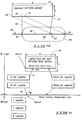
- Fig. 4 illustrates an implementation of the method shown in Fig. 3 on a pixel-by-pixel basis. It is to be understood that Fig. 4 and the following discussion of the pixel-by-pixel copy model are set forth to aid in understanding the 32-bit word-copy model discussed below.
- Fig. 4 shows an overlay pattern bit map 44.
- Bit map 44 has a height h and a width w.
- Bit map 44 defines an overlay pattern which is used in printing a printed image onto a print medium.
- a source or object 46 is shown and defines a fill area 48 which is to be printed with a portion of the overlay pattern in a manner directed by the printer control language.
- source 46 is an abstraction which provides boundary points which define the start and stop points for laying down a pattern.
- An output line 50 which is one full page width is provided and intersects source 46 at two points 52, 54.
- Source 46 and output line 50 determine a pair of boundary points 52, 54, which indicate or provide the boundary points between which a portion of a pattern will appear on a printed page.
- the segment, in this case line segment, between boundary points 52, 54 defines a fill area subset 58 which fills at least a portion of fill area 48.
- a pattern component may be built which is used to create the part of the line of the replicated pattern that is needed by the image processor to image the pending line of the source or fill area.
- anchor Integral to the concept of displaying or printing the same pattern tile over the area of a source is the concept of an "anchor.”
- the anchor point is sometimes called the pattern origin because it can be thought of as a single point from where the tiles are built in all directions from a central point.
- discussion will not be had concerning the details of vertical anchoring since the problem has been broken down to a single horizontal line that must be replicated from the pattern tile or overlay pattern bit map into the single output line 50.
- the vertical anchoring method was used to choose these particular lines.
- the invented method is directed to minimizing the amount of work which must be done by the printer on a particular line.
- the tiling process is one where the tiles are stacked vertically directly atop one another.
- the anchor point on a pattern tile is its upper left corner.
- point 53 This is the point to which the pixel from the overlay pattern bit map at point 49 will be copied.
- Rightward pixels from point 49 of the overlay pattern bit map are copied to the right of 53 on line 50.
- the pixels to the left of 53 are copied from the rightmost pixels near 47.
- the process just described does show how the horizontal AnchorX can be used, but it needs to be optimized for faster left-to-right operation starting at point 52 on the output line and working rightward as fast as possible until the pixel at 54 is copied. Therefore, the preferred implementation is to find which pixel 45 is to be copied to 52 using the appropriate algebraic mapping, and continue rightward reading pixels from the overlay pattern bit map and copying them to the output line 50 until the end at point 47 is reached, whereat reading is wrapped back to the start of the read-line at 49.
- source 46 is broken into a plurality of fill area subsets such as the one shown at 58, which as shown is a horizontal strip. Such subsets can be defined to run from the top of source 46 to the bottom of source 46.
- Each fill area subset is defined by a set of boundary points, points and lengths, or other fill area subset definitions which are used for determining where a particular portion of a pattern will appear on a print medium.
- Each set of boundary points or other definition for a fill area subset are determined and then a corresponding portion of the overlay pattern bit map is applied as described above. In so doing, image data defining a portion of a printed image is produced and written to an output band buffer which is thereafter used by the printer for printing a patterned image on a print medium.
- the method described above is advantageous because it provides only that portion of a pattern which is actually needed, and eliminates the need to pre-replicate the whole pattern height across the width of the page.
- the portion of the needed pattern corresponds to fill area 48 because that is the area which is to hold a portion of the overlay pattern when an image is printed.
- this method requires printer memory for only one output line 50, whereas previously a memory buffer h times larger (where h is the height of the overlay pattern bit map) was required since every line in the overlay pattern bit map had to be pre-replicated before the paper could move under the laser printing process. This is a substantial savings. For a half-inch high pattern tile, there is a 600-to-1 memory savings at 1200 dpi since there would be 600 lines in the height h to fill a half-inch high pattern.
- the pixel-by-pixel copy model discussed above illustrates one concept by which a pattern is printed on a print medium.
- the following discussion describes a preferred 32-bit word-copy model which is similar in some respects to the pixel-by-pixel copy model.
- the method is different in some respects because the level of programming complexity increases due to nuances and special requirements associated with copying and writing 32 bits at a time, as will be understood by those of skill in the art.
- FIGs. 5-11 illustrate a system in which 32-bit words are read from overlay pattern bit map 44. It will be appreciated, however, that words having lengths other than 32 bits may be read. Along with reading words having longer lengths, such as 32-bit words, problems arise stemming from the fact that the width of overlay pattern bit map 44 may not be evenly divisible by 32. Additionally, there can be other complications when the coordinate within the first word (known as the s coordinate) from the first word to be read from the overlay pattern bitmap, does not equal the coordinate within the first word (known as the d coordinate) to be written into the destination. These problems are addressed in Figs. 5 through 11, and discussed below.
- FIGs. 6-11 set forth basic flow charts which address the above-mentioned problems.
- the flow charts are described in C programming language which is a widely used and accepted programming language understood by those of skill in the art.
- Fig. 5 shows some basic definitional elements in the form of various registers and pointers utilized to implement one preferred aspect of this invention.
- quotation marks are used to identify the various terms which are being identified.
- the quotation marks are excluded.
- An overlay pattern bit map is shown at 44.
- Bit map 44 may also be referred to as an input tile bit map or a pattern memory block.
- the overlay pattern bit map defines an overlay pattern which is utilized in printing a printed image on a print medium.
- "W_origin" is a pointer that points to the start of output line 50 following two words of so-called start-up scratch memory.
- W_origin and other pointers in Fig. 5 are word patterns that point to byte addresses that are evenly divisible by four.
- Rstart points to the start of a line from bit map 44.
- the "R pointer register” (or “R ptr register” as it appears in Fig. 5) points to the next read-word in the input line.
- “*R” represents data in memory at the pointer address that is read from the input line.
- the "W pointer register” (or “W ptr register” as it appears in Fig. 5) points to the next write-word in the pattern replicated line.
- “*W” represents data in memory at the pointer address that is written to the output line.
- the “Rend pointer register” (or “Rend ptr register” as it appears in Fig. 5) points to the last word to be read from the input line.
- the "Wend pointer register” (or “Wend ptr register” as it appears in Fig. 5) points to the last write-word in the pattern replicated line for a particular pass.
- the "I register” is a temporary register that holds the 32-bit read-input from memory at "*R".
- the "C register” is a temporary register that holds carry read-input for a Carry Processing Case discussed below.
- the "N register” holds num_carry_bits which is the number of bits on the left of the "C register” that are being carried.
- R is the Read pointer, pointing to memory at a 32-bit memory location.
- R may be considered as a memory address.
- the actual binary value stored at the memory pointed to by “R” is represented by "*R”.
- R is the pointer, and "*R” represents the memory contents.
- W is the Write pointer, pointing in memory to a word in memory whose contents will be “*W” after a write operation completes.
- W is the pointer, and "*W” represents the memory contents that will be written.
- the compiler determines whether a register or a memory location is used to store the value of a register. It is possible in C to request that the compiler use registers for some specified variables. The judicious selection of which variables (or when those variables) should be implemented as registers can sometimes be controlled by optimizing compilers and sometimes controlled by the programmer. With the definitional elements set forth, attention is now directed to Figs. 6-11 for a more detailed explanation of the 32-bit word-copy model.
- Fig. 6 is a flow chart that sets forth in a global manner the 32-bit word-copy model which prepares one line of replicated pattern.
- Various of the boxes in Fig. 6 branch to other figures (Figs. 7-11) for a more detailed explanation of the operation performed thereby.
- box 100 is explained in more detail in Fig. 7 which sets forth a variable set procedure which defines a number of useful variables for a computer program that implements the invention
- box 114 is explained in more detail in Fig. 8 which addresses the situation when the first bit within the first read word (s) may or may not match the first writing bit (d) in the destination; box 118 is explained in more detail in Fig.
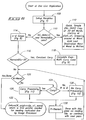
- the first step in Fig. 6 is shown at box 100 and comprises a variable setup step in which selected variables are defined. These variables are set forth in more detail in Fig. 7, which is a flow chart that sets forth a variable setup procedure. More specifically and referring to Fig. 7, box 200 defines a number of variables. Given the routine inputs, clip_x1 and right_x2, which are inclusive device space pixel coordinates where the source intersects the pending destination line needed, and also given Rstart the starting word pointer, box 200 calculates some useful word-oriented begin/end read and write coordinates and pointers. More specifically, clip_x1_word, right_x2_word, and pointers RendMinus, W and Wend are initialized.
- AnchorX is the coordinate in destination coordinate space where a specified location in the pattern tile is fixed. This position is often the upper left corner of the tile, but it could be any point on the tile. Here, the upper-left corner is used as the point on the tile that is anchored. Referring to boxes 210 through 218, an example using a pixel coordinate of zero for the left-most printable dot on the page is set forth.
- the specified AnchorX for the pattern and clip_x1 have various wrap-around cases which are simplified by considering the relative coordinates of each in box 210. In either case, boxes 212 and 214 calculate the relative starting position for input tile line reading, mod_x.
- box 216 calculates the relative bit coordinates within the first 32-bit word for reading and writing which are s and d, respectively.
- An s value of zero means that the most significant leftward bit in the read word will be used.
- a bit_delta is calculated at box 218 which is the relative shift in bits between the read and write words.
- the Read pointer R and RemainBits are also calculated, which are the initial Read pointer and the number of dangling bits on the end of the read tile line. For example, if the tile width is 33, then RemainBits is 1, because 1 bit dangles off of the end of the first word.
- a test is made to determine if both bit_delta and RemainBits are zero. If both are zero, then at box 112, a simple copy may be done in any number of ways, including using standard copy libraries. This is the simplest case which is a loop of reading and writing 32-bit words until the right-most word of the tile is copied, and repeating the process until sufficient output is generated.
- box 112 could be that shown in Fig. 10 by replacing box 520 with a loop back to above box 500. Sufficient output is generated through a test which is done to determine if the W has advanced beyond the Wend pointer. If, on the other hand, the answer at box 110 is "no", then the method advances to box 114 which is referred to as the s-d cases.
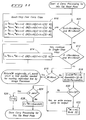
- the s-d cases of box 114 are set forth in more detail in Fig. 8.
- R word of memory pointed to by R
- + + indicates that the R pointer is post-incremented.
- the number of carry bits is set to 32-s because that is the number of bits on the left part of the C register that are carried for this case.
- the right unused bits in the C register are maintained in a zero state.
- box 316 adjusts d by the value of s, zeroes s, and recalculates the clip_x1 value as shown.
- a check is made to determine if the R pointer is beyond the RendMinus value. If so, a special narrow case adjustment, shown at box 320 is made. If not, the s-d cases are completed.
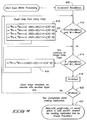
- An even-width carry case means that the tile width in pixels is a simple integer multiple of 32. Examples of possible tile widths are 32, 64, 96 . . . pixels in width. Having such a tile width means that neither the amount of carry nor the amount of shift can change at the end of any read-pass across the input tile. These cannot change since there are no dangling bits to change them. Therefore, the contents of the Carry register C will remain invariant while looping, as will the number of carry bits N. A constant C and N make this case relatively simple compared to the Carry case discussed below.
- RendMinus is incremented to point just beyond Rend, the last word read. This is a simplification that takes advantage of the even read-stop sequence. No advance warning on the read-tile loop is needed because no bits are dangling at the end of the word.
- RendMinus After adjusting RendMinus, all reads will be for the condition when R is less than RendMinus or (R ⁇ RendMinus).
- a check is made to see if W is less than or equal to Wend and the Read pointer R is far enough to the left so that four words can be read without reading beyond the end of the tile. When there are at least four reads remaining for this pass over the tile width, then at box 412, four very fast read/write combinations are performed.
- Box 412 is known as a quad-step fast carry copy. It should be understood that empirical or theoretical analysis may be done on the processor and compiler being used to determine if doing quad-steps, such as box 412, speed up or slow down the processing. If the quad-step process slows down the CPU system, then the quad-step process is not used, and single-stepping is done as in box 416. The same analysis applies to other later cases where quad-steps are shown in the flow charts. In some processors with instruction cache, it is possible from theory to select whether quad-steps will speed up the processing. When quad-steps are faster, part of the reason is usually because the cost of the looping overhead for the loop termination is reduced by spreading over multiple operations.
- each of the steps is exactly the same as a single step in box 416 when we are within 4 words of the right side of the tile.
- Each step is as follows:
- any remaining words of the read operation from this pass on the tile are finished.
- the R pointer register is reloaded to point to the start position on the left of the input tile line at Rstart.
- a check is made to determine if sufficient writing has been accomplished. If not, a loop is made back to the next set of quad-steps at boxes 410 and 412, and/or single steps at boxes 414 and 416.
- W wend
- a value is returned which is the word pointer address that will be used by the image processor to start reading the pattern at the intersection coordinate with the source. This address is (W_origin + clip_x1_word).
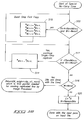
- a check to see if replication is complete is made by comparing the W pointer with the Wend pointer at box 516. If complete, the whole subroutine is exited as before, which would use an immediate return or branch to box 122 of Fig. 6. If the routine is not yet done, then Carry processing resumes at box 520 by loading the C register with the RemainBits that are dangling off the last word of the tile. Also, N is set to equal the RemainBits value.
- Carry processing is the most complicated case because the number of carry bits can accumulate to exceed or equal the number that can be held in the 32-bit Carry register.
- Boxes 600 through 614 are the same as described above for the complete even-width Carry case (boxes 410 through 416). The reader is referred to the discussion above relating to such operation.
- a check is made to determine if writing the output is finished. If the answer at box 616 is yes, then return immediately to box 122 in Fig. 6. If not, then at box 618 new dangling bits are added to the Carry register.
- the next C register is calculated from the old C register bits (of which only N of the left-most ones are significant) which are Ored with the value (*R > > N) in memory at the position pointed to by the R pointer. Then, a value OverShift is assigned the value 32-N for later use.
- the OverShift is the number of unused bits commencing the processing at box 618.
- the new N is set equal to the old value + RemainBits because RemainBits is the extra number of bits that must be carried along on the next pass, being the dangling amount that are read from the end of the tile to complete the current pass.
- the new N has overflowed beyond 31 bits, or it has not. If the new N is 32 bits, the Carry register is full, and it can be written to memory and cleared immediately. If N exceeds 32, the Carry register must also be written to memory, and new Carry Register is recalculated at box 628. Summarizing, a check is made at box 620 to determine if C will he written at box 622.
- N N-32 . If N is less than 32 in box 620, then processing continues without writing the Carry register because there is no overflow condition, and the Carry register must be carried into the next Carry processing case on the next swath reading across the input tile.
- the above-described invention is useful because of the inherent printer memory savings produced thereby. This is because, unlike prior systems, a pattern need not be pre-replicated across an entire page width. Because of this, valuable memory is saved. It will be understood that certain digital printers, such as laser printers, move a print medium such a paper, through the printing process at a constant speed. This speed is maintained from start to finish. Thus, in the past, it became convenient to pre-replicate a pattern across an entire page width to ensure that the printer, and particularly the laser, had enough work to do. By doing this, one was assured that the printer would not run out of work thereby producing a so-called punt which may be thought of as a work outage. Consequently, it became commonplace to build up the printer work before starting the paper on its print journey. Once enough work was built up, the paper was started on its print journey.
- the preferred model discussed just below is directed to providing a means for ensuring that the minimum number of video DMA band buffers are pre-rasterized so that the Image Processor Task can just win every race with the video DMA without using an excess of printer memory.
- Cost Overhead + (ObjectWidth * WidthCost) + (Replications * ReplicationCost)
- the above model considers three parameters: Overhead, Width Cost, and Replication Cost.
- the model assesses on a line-by-line (fill area subset-by-fill area subset) basis the real time processing requirements for the purpose of identifying which lines, strips, or fill area subsets need prerasterization to avoid a print overrun or so-called punt.
- Overhead is a parameter which takes into account the overhead time requirements associated with the operation.
- the Width Cost parameter (the product of the ObjectWidth and the WidthCost) takes into account the amount of time associated with processing an object having a particular width.
- the Replication Cost parameter (the product of Replications and ReplicationCost) takes into account the time associated with looping decisions.
- the costs generated may be used to determine which strips need to be prerasterized to avoid a print overrun. Such may be conveniently determined through a comparison of the generated cost with a known threshold.
- the model may be used to provide a trade-off between pre-rasterization and pre-tiling. For example, the maximum source or fill area to which a pattern is to be applied would be recorded while a particular page is being built.
- the maximum width is the width that would be used for pre-tiling. In many cases, this width would be substantially less than the physical page width. Therefore, even in the case where pre-tiling would be used, the memory requirements would sometimes be substantially less in most complex pages.
- the above cost model assists the present invention in racing the laser or staying ahead of the laser operation during the preparation of a pattern for printing on a print medium.
- bit map pattern memory block 44 In some cases the rectangular bit map may be described by a set of vector fill commands. If the set of vector fill commands is sufficiently simple, it is possible to skip the preparation of the pattern memory block, and make the Write Pattern Replicated Line directy by extending the same types of begin-skip-repeat steps that are previously taught. Such a vector fill pattern is included as one of the different means of applying this invention.
Landscapes
- Engineering & Computer Science (AREA)
- General Engineering & Computer Science (AREA)
- Physics & Mathematics (AREA)
- General Physics & Mathematics (AREA)
- Theoretical Computer Science (AREA)
- Record Information Processing For Printing (AREA)
- Facsimile Image Signal Circuits (AREA)
Applications Claiming Priority (2)
| Application Number | Priority Date | Filing Date | Title |
|---|---|---|---|
| US637060 | 1996-04-24 | ||
| US08/637,060 US5852711A (en) | 1996-04-24 | 1996-04-24 | Efficient pattern use in printers |
Publications (3)
| Publication Number | Publication Date |
|---|---|
| EP0803837A2 true EP0803837A2 (fr) | 1997-10-29 |
| EP0803837A3 EP0803837A3 (fr) | 2000-12-20 |
| EP0803837B1 EP0803837B1 (fr) | 2004-12-22 |
Family
ID=24554375
Family Applications (1)
| Application Number | Title | Priority Date | Filing Date |
|---|---|---|---|
| EP96116705A Expired - Lifetime EP0803837B1 (fr) | 1996-04-24 | 1996-10-17 | Méthode d'impression utilisant des motifs de surimposition |
Country Status (4)
| Country | Link |
|---|---|
| US (1) | US5852711A (fr) |
| EP (1) | EP0803837B1 (fr) |
| JP (1) | JP3311956B2 (fr) |
| DE (1) | DE69634073T2 (fr) |
Families Citing this family (9)
| Publication number | Priority date | Publication date | Assignee | Title |
|---|---|---|---|---|
| US5881226A (en) * | 1996-10-28 | 1999-03-09 | Veneklase; Brian J. | Computer security system |
| US6971027B1 (en) * | 1999-04-01 | 2005-11-29 | Veneklase Brian J | Computer security system |
| US6894796B1 (en) | 2000-05-12 | 2005-05-17 | International Business Machines Corporation | Method, system, and logic for selecting line work and control data for a pixel from multiple objects of line work data provided for the pixel |
| US6850338B1 (en) | 2000-05-12 | 2005-02-01 | International Business Machines Corporation | Method, system, program, and data structure for generating raster objects |
| US6804411B1 (en) * | 2000-05-15 | 2004-10-12 | International Business Machines Corporation | Method, system, and program for decompressing and aligning line work data from multiple objects |
| US7394568B1 (en) | 2000-05-15 | 2008-07-01 | Infoprint Solutions Company Llc | Method, system, and logic for selecting pixel data from multiple objects |
| US6449328B1 (en) | 2000-05-15 | 2002-09-10 | International Business Machines Corporation | Method and apparatus for shifting data from registers |
| US6961134B1 (en) | 2000-05-15 | 2005-11-01 | International Business Machines Corporation | Method, system, and logic using multiplexers to select data for pixels from multiple objects |
| US7130073B2 (en) * | 2002-05-10 | 2006-10-31 | Texas Instruments Incorporated | Efficient storage and rendering of patterns in a printer |
Citations (2)
| Publication number | Priority date | Publication date | Assignee | Title |
|---|---|---|---|---|
| US5129049A (en) | 1991-05-16 | 1992-07-07 | Hewlett-Packard Company | Method and apparatus for preventing print overruns |
| US5479587A (en) | 1992-09-03 | 1995-12-26 | Hewlett-Packard Company | Page printer having adaptive data compression for memory minimization |
Family Cites Families (5)
| Publication number | Priority date | Publication date | Assignee | Title |
|---|---|---|---|---|
| US5509115A (en) * | 1990-08-08 | 1996-04-16 | Peerless Systems Corporation | Method and apparatus for displaying a page with graphics information on a continuous synchronous raster output device |
| US5204916A (en) * | 1991-08-06 | 1993-04-20 | Eastman Kodak Company | Tile-oriented technique for collectively performing image rotation, scaling and digital halftone screening |
| US5539865A (en) * | 1992-11-10 | 1996-07-23 | Adobe Systems, Inc. | Method and apparatus for processing data for a visual-output device with reduced buffer memory requirements |
| US5602976A (en) * | 1993-02-23 | 1997-02-11 | Adobe Systems Incorporated | Method and apparatus for saving printer memory |
| JP3554034B2 (ja) * | 1994-09-02 | 2004-08-11 | キヤノン株式会社 | カラー印刷装置及びその方法 |
-
1996
- 1996-04-24 US US08/637,060 patent/US5852711A/en not_active Expired - Lifetime
- 1996-10-17 DE DE69634073T patent/DE69634073T2/de not_active Expired - Lifetime
- 1996-10-17 EP EP96116705A patent/EP0803837B1/fr not_active Expired - Lifetime
-
1997
- 1997-03-17 JP JP06357497A patent/JP3311956B2/ja not_active Expired - Fee Related
Patent Citations (2)
| Publication number | Priority date | Publication date | Assignee | Title |
|---|---|---|---|---|
| US5129049A (en) | 1991-05-16 | 1992-07-07 | Hewlett-Packard Company | Method and apparatus for preventing print overruns |
| US5479587A (en) | 1992-09-03 | 1995-12-26 | Hewlett-Packard Company | Page printer having adaptive data compression for memory minimization |
Also Published As
| Publication number | Publication date |
|---|---|
| EP0803837A3 (fr) | 2000-12-20 |
| DE69634073D1 (de) | 2005-01-27 |
| JP3311956B2 (ja) | 2002-08-05 |
| JPH1035055A (ja) | 1998-02-10 |
| EP0803837B1 (fr) | 2004-12-22 |
| US5852711A (en) | 1998-12-22 |
| DE69634073T2 (de) | 2006-03-02 |
Similar Documents
| Publication | Publication Date | Title |
|---|---|---|
| EP0396661B1 (fr) | Commande de memoire de page dans un processeur d'images de trame | |
| US5303334A (en) | System for generating a rasterized graphic image | |
| TWI281639B (en) | Method for managing state variables for rendering primitives, apparatus for rendering a scene including primitives, and machine readable medium | |
| EP0583101B1 (fr) | Méthode et appareil générateur de motif de caractères | |
| US5852711A (en) | Efficient pattern use in printers | |
| US6429950B1 (en) | Method and apparatus for applying object characterization pixel tags to image data in a digital imaging device | |
| US5146554A (en) | Page memory control in a raster image processor employed for digital halftoning | |
| EP0575134B1 (fr) | Méthode et dispositif d'impression selon un langage graphique | |
| US4752894A (en) | Color plotter controller | |
| US20060028701A1 (en) | Color image forming apparatus | |
| US20090091564A1 (en) | System and method for rendering electronic documents having overlapping primitives | |
| US6091418A (en) | Printer with procedure for pattern tiling and scaling | |
| US20040190017A1 (en) | Rendering a printing device pixel map | |
| US5517601A (en) | High speed apparatus and method for rasterization of font glyphs | |
| JP5079341B2 (ja) | 印刷データ処理装置 | |
| EP0464794A2 (fr) | Système de génération de motif peint et méthode de peinture de motif utilisant le système | |
| KR900002230B1 (ko) | 프린터 제어장치 | |
| US5758044A (en) | Method and apparatus for rendering using a band by band depth adjustment | |
| JP4404117B2 (ja) | 画像処理回路、表示装置及び印刷装置 | |
| US6331897B1 (en) | Image processing method and apparatus in which a table stores by a scan line unit memory addresses at each of which a function is stored for developing an image for one line into a memory | |
| KR900016896A (ko) | 고품질 패턴 발생 방법 및 장치 | |
| US7280250B2 (en) | Method and apparatus for rendering large patterns in a small memory printer | |
| JPH05181626A (ja) | 印字装置 | |
| JPH06110888A (ja) | 文書出力方法及び装置 | |
| JPH04144762A (ja) | 印字装置 |
Legal Events
| Date | Code | Title | Description |
|---|---|---|---|
| PUAI | Public reference made under article 153(3) epc to a published international application that has entered the european phase |
Free format text: ORIGINAL CODE: 0009012 |
|
| AK | Designated contracting states |
Kind code of ref document: A2 Designated state(s): DE FR GB |
|
| PUAL | Search report despatched |
Free format text: ORIGINAL CODE: 0009013 |
|
| AK | Designated contracting states |
Kind code of ref document: A3 Designated state(s): DE FR GB |
|
| RAP1 | Party data changed (applicant data changed or rights of an application transferred) |
Owner name: HEWLETT-PACKARD COMPANY, A DELAWARE CORPORATION |
|
| 17P | Request for examination filed |
Effective date: 20010522 |
|
| 17Q | First examination report despatched |
Effective date: 20021025 |
|
| GRAP | Despatch of communication of intention to grant a patent |
Free format text: ORIGINAL CODE: EPIDOSNIGR1 |
|
| GRAS | Grant fee paid |
Free format text: ORIGINAL CODE: EPIDOSNIGR3 |
|
| GRAA | (expected) grant |
Free format text: ORIGINAL CODE: 0009210 |
|
| AK | Designated contracting states |
Kind code of ref document: B1 Designated state(s): DE FR GB |
|
| REG | Reference to a national code |
Ref country code: GB Ref legal event code: FG4D |
|
| REF | Corresponds to: |
Ref document number: 69634073 Country of ref document: DE Date of ref document: 20050127 Kind code of ref document: P |
|
| PLBE | No opposition filed within time limit |
Free format text: ORIGINAL CODE: 0009261 |
|
| STAA | Information on the status of an ep patent application or granted ep patent |
Free format text: STATUS: NO OPPOSITION FILED WITHIN TIME LIMIT |
|
| 26N | No opposition filed |
Effective date: 20050923 |
|
| ET | Fr: translation filed | ||
| PGFP | Annual fee paid to national office [announced via postgrant information from national office to epo] |
Ref country code: FR Payment date: 20071017 Year of fee payment: 12 |
|
| REG | Reference to a national code |
Ref country code: FR Ref legal event code: ST Effective date: 20090630 |
|
| PG25 | Lapsed in a contracting state [announced via postgrant information from national office to epo] |
Ref country code: FR Free format text: LAPSE BECAUSE OF NON-PAYMENT OF DUE FEES Effective date: 20081031 |
|
| REG | Reference to a national code |
Ref country code: GB Ref legal event code: 732E Free format text: REGISTERED BETWEEN 20120329 AND 20120404 |
|
| PGFP | Annual fee paid to national office [announced via postgrant information from national office to epo] |
Ref country code: DE Payment date: 20121029 Year of fee payment: 17 |
|
| PGFP | Annual fee paid to national office [announced via postgrant information from national office to epo] |
Ref country code: GB Payment date: 20121025 Year of fee payment: 17 |
|
| GBPC | Gb: european patent ceased through non-payment of renewal fee |
Effective date: 20131017 |
|
| REG | Reference to a national code |
Ref country code: DE Ref legal event code: R119 Ref document number: 69634073 Country of ref document: DE Effective date: 20140501 |
|
| PG25 | Lapsed in a contracting state [announced via postgrant information from national office to epo] |
Ref country code: GB Free format text: LAPSE BECAUSE OF NON-PAYMENT OF DUE FEES Effective date: 20131017 |
|
| PG25 | Lapsed in a contracting state [announced via postgrant information from national office to epo] |
Ref country code: DE Free format text: LAPSE BECAUSE OF NON-PAYMENT OF DUE FEES Effective date: 20140501 |