EP0803835B2 - Space saving electric connector for an IC memory card - Google Patents
Space saving electric connector for an IC memory card Download PDFInfo
- Publication number
- EP0803835B2 EP0803835B2 EP97201929A EP97201929A EP0803835B2 EP 0803835 B2 EP0803835 B2 EP 0803835B2 EP 97201929 A EP97201929 A EP 97201929A EP 97201929 A EP97201929 A EP 97201929A EP 0803835 B2 EP0803835 B2 EP 0803835B2
- Authority
- EP
- European Patent Office
- Prior art keywords
- blade
- support
- branch
- electrical connector
- connector according
- Prior art date
- Legal status (The legal status is an assumption and is not a legal conclusion. Google has not performed a legal analysis and makes no representation as to the accuracy of the status listed.)
- Expired - Lifetime
Links
Images


Classifications
-
- G—PHYSICS
- G06—COMPUTING OR CALCULATING; COUNTING
- G06K—GRAPHICAL DATA READING; PRESENTATION OF DATA; RECORD CARRIERS; HANDLING RECORD CARRIERS
- G06K7/00—Methods or arrangements for sensing record carriers, e.g. for reading patterns
- G06K7/06—Methods or arrangements for sensing record carriers, e.g. for reading patterns by means which conduct current when a mark is sensed or absent, e.g. contact brush for a conductive mark
-
- G—PHYSICS
- G06—COMPUTING OR CALCULATING; COUNTING
- G06K—GRAPHICAL DATA READING; PRESENTATION OF DATA; RECORD CARRIERS; HANDLING RECORD CARRIERS
- G06K7/00—Methods or arrangements for sensing record carriers, e.g. for reading patterns
- G06K7/0013—Methods or arrangements for sensing record carriers, e.g. for reading patterns by galvanic contacts, e.g. card connectors for ISO-7816 compliant smart cards or memory cards, e.g. SD card readers
- G06K7/0056—Methods or arrangements for sensing record carriers, e.g. for reading patterns by galvanic contacts, e.g. card connectors for ISO-7816 compliant smart cards or memory cards, e.g. SD card readers housing of the card connector
- G06K7/0069—Methods or arrangements for sensing record carriers, e.g. for reading patterns by galvanic contacts, e.g. card connectors for ISO-7816 compliant smart cards or memory cards, e.g. SD card readers housing of the card connector including means for detecting correct insertion of the card, e.g. end detection switches notifying that the card has been inserted completely and correctly
-
- G—PHYSICS
- G06—COMPUTING OR CALCULATING; COUNTING
- G06K—GRAPHICAL DATA READING; PRESENTATION OF DATA; RECORD CARRIERS; HANDLING RECORD CARRIERS
- G06K7/00—Methods or arrangements for sensing record carriers, e.g. for reading patterns
- G06K7/0013—Methods or arrangements for sensing record carriers, e.g. for reading patterns by galvanic contacts, e.g. card connectors for ISO-7816 compliant smart cards or memory cards, e.g. SD card readers
- G06K7/0021—Methods or arrangements for sensing record carriers, e.g. for reading patterns by galvanic contacts, e.g. card connectors for ISO-7816 compliant smart cards or memory cards, e.g. SD card readers for reading/sensing record carriers having surface contacts
Definitions
- the present invention relates to an electrical connector for connecting an electronic memory card comprising on one of its main faces a plurality of electrical contact pads aligned parallel to the insertion direction of the card in a read-write device.
- the invention relates to a connector as defined in the preamble of claim 1.
- each contact blade is in the form of a beam embedded at one of its ends in the insulating material of the support and which extends longitudinally from this end to terminate in a free curved contact end.
- This design has the disadvantage of being cumbersome because of the length of each contact blade necessary for it to have sufficient elasticity to ensure a given contact force with a corresponding range of a card.
- the median ply is located towards a lateral edge of the connector and the means for fixing the blade are located in the center of the connector.
- the invention proposes a connector of the type mentioned above, characterized in that the median fold is turned towards the median plane of the connector which extends substantially to the center of the contact areas of the card. microcircuit when the latter is in read-write position.
- the connector 10 illustrated on the Figures 1 to 5 is essentially constituted by a housing or support of insulating material 12 and a lid 14 of molded plastic material, and by a series of electrical conductors 16.
- the housing or support 12 is essentially constituted by a horizontal plate 18 which delimits a flat face 20 and a side wall 22 of substantially rectangular contour.
- the upper face 20 of rectangular contour comprises a series of housings 24 formed recess in the upper face 20 of the plate 18.
- the connector has a general design symmetry with respect to a median vertical plane P indicated on the Figures 3 and 4 and the support 12 thus comprises two series of four housings 24 aligned in pairs.
- Each housing 24 is in the form of a notch with parallel edges or faces 26 which is delimited by a housing bottom 28 which extends in a plane parallel to the upper planar face 20 of the housing 12.
- Each housing 24 is designed to receive an electrical conductor 16 which is made of an elastically deformable conductive material.
- Each element 16 is thus made in the form of a cut and folded contact blade.
- Each contact blade 16 extends in a longitudinal general direction contained in a vertical plane parallel to the parallel faces 26 of the corresponding housing 24 and perpendicular to the face 20 of the support 12.
- Each contact blade 16 has a convex curved first end 30 which is adapted to cooperate with a corresponding range (not shown) of an electronic memory card which is capable of being introduced, in a direction I parallel to the housings 24, in a read-write device (not shown) equipped with a connector 10 according to the invention.
- each blade 16 is extended by a nose 32 substantially parallel to the flat face 20 whose function will be explained later.
- Each contact blade 16 also has a connecting end 34 which extends vertically, that is to say in a direction perpendicular to the upper face 20, along the side wall 22 of the support 12 and which ends with a tab folded at right angles 36 allowing the connection of each blade 16 on a track of a printed circuit board (not shown), for example according to the technique of the flat report of the components.
- the curved contact end 30 and the connecting end 34 are connected to each other by a connecting middle portion 38 in the form of a hairpin.
- the medial connection part 38 of each blade 16 thus comprises a first branch 40 which extends in a direction substantially parallel to the flat face 20 of the support 12 and a second branch 42 forming an acute angle with respect to the first branch 30 and which are interconnected by the median fold 44 in the shape of a U.
- This medial fold 44 is turned towards the center of the connector that is to say it is located substantially to the right of the chip of the smart card when the latter is in the read-write position.
- This geometric arrangement gives the connector according to the invention a very large compactness and a small footprint on the printed circuit board on which it will be mounted.
- the length of the connector, measured parallel to the longitudinal direction of the blades 16 is as small as possible.
- the free end 46 of the first leg 40 is extended by the connecting end 34 of the blade 16 while the free end of the second leg 42 of the middle connecting portion 38 is extended by the curved contact end. 30.
- the free end 46 of the first limb 40 of each blade 16 is kept flush so that the median connecting portion 38, and in particular the first limb 40 can flex elastically according to a direction D substantially perpendicular to the plane of the flat face of the support 12.
- the end 46 is clamped between a flat portion 48 of the support 12 parallel to the flat face 20 of the latter, but offset vertically downwardly relative to the upper face 20, and a corresponding surface portion 50 formed vis-à-vis the inner face 52 of the cover 14 which bears against the flat upper face 20 of the support 12.
- the cover 14 is fixed to the housing 12 and by hot crimping with two studs 54 made integrally with the cover 14, which extend vertically downwards from the lower face 52 and which are received in two corresponding holes 56 formed in the flat upper wall 18 of the support 12.
- the lid 14 is thus held firmly on the support 12 to clamp the ends 46 of the first legs 44 of the central connecting portions 38 of the blades 16 to ensure their embedding effect in housing delimited by surfaces 48 and 50.
- the cover 14 has a series of open slots 60 aligned opposite the housings 24 and blades 16 .
- the connector 10 is of the type with eight housings 24 but with six contact blades 16 and the cover 14 therefore has only six open slots 60 which are parallel to each other and opposite in pairs.
- each contact blade 16 Prior to the introduction of the cover 14, each contact blade 16 is placed in the support 12 by lateral introduction, that is to say substantially in a direction parallel to the direction of introduction I.
- each contact blade 16 is forced into a corresponding slot 64 of the support 12.
- Each hooking lug 62 extends substantially parallel to the branch 40 of the connecting middle portion 38 to which it is connected by a cross member 65.
- Each slot 64 is delimited upwards by a transverse bridge 66 formed integrally with the support 12 as can be seen in FIG. figure 5 .
- Each attachment lug 62 has a protruding bead 68 that extends laterally outwardly beyond the connecting end 34 of the blade 16 opposite an inner face 70 of a peripheral collar 72 of the cover 14 which thus opposes any accidental lateral escape of the contact blade 16.
- each contact blade 30 In mounted position, and as can be seen in particular on the figure 3 the spout 32 of each contact blade 30 is held resiliently against a face-to-face portion 74 of the underside 52 of the cover 14 to determine a precise geometrical position of rest of the curved contact portion 30 of each of the blades 16 so that it occupies a precise geometric position and determined relative to the support 12.
- the cover 14 thus holds all the blades 16 slightly elastically preload in a precise geometric position.
- This design has the advantage of making it possible to vary the contact force of the contacts on the pads of the memory card as a function of the exact geometry of the folding of the middle portion of connection 38, while ensuring a precise rating of overflow. the curved contact portion 30 with respect to the upper face 76 of the cover 14 of the connector 10.
- the connector 10 which has just been described thus has a very great compactness while ensuring optimum performance of electrical contact of the blades 16 on the pads of a card inserted into a read-write device equipped with a connector according to the invention. invention.
- the establishment and fixing of the blades 16 in the support 12 is mechanically ensured by locking the harpoon hooking lugs 62 during the mechanical assembly of the blades 16 in the support or casing 12 molded beforehand.
- each contact blade 16 which extends from the embedded portion 46 to the curved contact portion 30 is thinned and thus has a thickness "e" reduced with respect to the thickness of the metal strip wherein the contact blades are made by cutting and folding.
- This reduced thickness increases the elastic deformation capacity of each contact blade and increases the deflection stroke of each contact blade, despite the particularly small total height of the connector.
- each contact blade 16 it is possible to provide a hole (not shown) in the recessed portion 46 of the blade, this hole receiving the free end of the nose 32 when the blade is in position flexed.
- Thinning of the intermediate section of each blade is achieved by local crushing, before cutting the blades. This mode of obtaining the thinning "e” makes it possible to increase the mechanical characteristics of the material in the zone hardened by crushing.
- the design of the body of insulating material 12 with a bottom 18 and parallel faces 26 to define the housing 24 which receive the contact blades 12 is particularly advantageous in that it provides a very good electrical isolation of the contacts relative to each other. This insulation is completed by the complementary design of the slots 60 of the cover 14.
- the middle loops or plies 44 of the contact blades 16 are turned towards the "center” of the connector, that is to say towards the median plane P which, when a card is in the position of use, extends substantially to the right of the center of the contact pads of the microcircuit card.
- This geometric design makes it possible to give the connector a very small overall length (measured in the width direction considering the figure 3 ) and therefore a very small footprint on the printed circuit board that receives it.
- the connector which has just been described can be used in a read-write device in which the electronic memory card moves, with respect to the connector, in a direction perpendicular to its general plane and perpendicular to the plane of the face 20.
- the design of the contact blades 16 provides a self-cleaning effect due to the cooperation of the curved ends 30 with the conductive tracks of the card during the final landing phase of the latter. .
Landscapes
- Engineering & Computer Science (AREA)
- Artificial Intelligence (AREA)
- Computer Vision & Pattern Recognition (AREA)
- Physics & Mathematics (AREA)
- General Physics & Mathematics (AREA)
- Theoretical Computer Science (AREA)
- Coupling Device And Connection With Printed Circuit (AREA)
- Connector Housings Or Holding Contact Members (AREA)
- Details Of Connecting Devices For Male And Female Coupling (AREA)
Description
La présente invention concerne un connecteur électrique pour le raccordement d'une carte à mémoire électronique comportant sur une de ses faces principales une pluralité de plages de contact électrique alignées parallèlement à la direction d'introduction de la carte dans un dispositif de lecture-écriture.The present invention relates to an electrical connector for connecting an electronic memory card comprising on one of its main faces a plurality of electrical contact pads aligned parallel to the insertion direction of the card in a read-write device.
L'invention concerne un connecteur tel que défini au préambule de la revendication 1.The invention relates to a connector as defined in the preamble of
Selon une conception connue, qui est par exemple décrite et représentée dans le document
Cette conception a pour inconvénient d'être encombrante du fait de la longueur de chaque lame de contact nécessaire pour qu'elle présente une élasticité suffisante lui permettant d'assurer une force de contact déterminée avec une plage correspondante d'une carte.This design has the disadvantage of being cumbersome because of the length of each contact blade necessary for it to have sufficient elasticity to ensure a given contact force with a corresponding range of a card.
Il a déjà été proposé dans le document
Selon la conception proposée dans ce document, le pli médian est situé vers un bord latéral du connecteur et les moyens de fixation de la lame sont situées au centre du connecteur.According to the design proposed in this document, the median ply is located towards a lateral edge of the connector and the means for fixing the blade are located in the center of the connector.
Cette conception n'est donc pas entièrement satisfaisante notamment en ce qu'elle impose un mode de fixation peu satisfaisant du point de vue de la fabrication en grande série. Elle ne permet notamment pas de monter le connecteur sur une plaque support à circuit imprimé selon la technique "CMS". Pour remédier à cet inconvénient, et comme le propose le document
Elle ne permet pas non plus de maîtriser avec précision l'altitude des extrémités de contact des lames de contact qui font saillie au dessus de la face supérieure du support.It also does not allow to control precisely the altitude of the contact ends of the contact blades which protrude above the upper face of the support.
Afin de remédier à ces inconvénients, l'invention propose un connecteur du type mentionné précédemment, caractérisé en ce que le pli médian est tourné vers le plan médian du connecteur qui s'étend sensiblement au droit du centre des plages de contact de la carte à microcircuit lorsque cette dernière est en position de lecture-écriture.In order to overcome these drawbacks, the invention proposes a connector of the type mentioned above, characterized in that the median fold is turned towards the median plane of the connector which extends substantially to the center of the contact areas of the card. microcircuit when the latter is in read-write position.
Selon d'autres caractéristiques de l'invention :
- l'extrémité libre de la première branche de la partie médiane de liaison de la lame est encastrée dans un logement du support, et la première branche s'étend en regard d'un logement formé en vis-à-vis dans la face plane du support pour permettre un fléchissement de la première branche selon une direction sensiblement perpendiculaire à la face plane du support ;
- l'extrémité incurvée de contact de chaque lame s'étend sensiblement au droit de l'extrémité libre encastrée de la première branche de la partie médiane de liaison de la lame;
- le logement en regard duquel s'étend la première branche de la partie médiane de liaison de la lame comporte un fond qui limite le fléchissement de la première branche ;
- l'extrémité incurvée de contact de chaque lame se prolonge par un bec qui est sollicité élastiquement en appui contre une surface de butée ;
- le connecteur comporte un couvercle en matériau isolant qui prend appui sur la face plane du support et qui comporte une série de fentes parallèles à travers chacune desquelles fait saillie une extrémité incurvée de contact d'une lame ;
- la surface de butée est formée en vis-à-vis dans la face interne du couvercle qui s'étend en regard de la face plane du support ;
- l'extrémité de raccordement de chaque lame s'étend selon une direction perpendiculaire au plan de la face plane du support en éloignement de la seconde branche de la partie médiane de liaison de la lame et le long d'une face latérale du support ;
- chaque lame de contact est réalisée sous la forme d'une bande métallique découpée et pliée d'épaisseur sensiblement constante, et chaque bande de contact comporte un tronçon intermédiaire d'épaisseur réduite réalisé notamment par écrasement, qui s'étend entre les extrémités de contact et de raccordement de la lame ;
- le tronçon d'épaisseur réduite s'étend entre l'extrémité libre de la première branche et l'extrémité libre de la seconde branche ;
- l'extrémité incurvée de contact est située longitudinalement entre le pli médian qui relie entre elles les première et seconde branches de la partie médiane de liaison, et l'extrémité de raccordement.
- the free end of the first branch of the median connecting portion of the blade is embedded in a housing of the support, and the first branch extends opposite a housing formed vis-a-vis in the flat face of the support for allowing a deflection of the first branch in a direction substantially perpendicular to the planar face of the support;
- the curved end of contact of each blade extends substantially to the right of the free end embedded in the first branch of the median connecting portion of the blade;
- the housing opposite which extends the first branch of the median connecting portion of the blade comprises a bottom which limits the deflection of the first branch;
- the curved end of contact of each blade is extended by a spout which is biased resiliently against a abutment surface;
- the connector comprises a cover made of insulating material which bears on the flat face of the support and which comprises a series of parallel slots through which each protrudes a curved end of contact of a blade;
- the abutment surface is formed vis-a-vis in the inner face of the cover which extends opposite the flat face of the support;
- the connecting end of each blade extends in a direction perpendicular to the plane of the flat face of the support away from the second branch of the median connecting portion of the blade and along a side face of the support;
- each contact blade is made in the form of a cut and folded metal strip of substantially constant thickness, and each contact strip comprises an intermediate portion of reduced thickness produced in particular by crushing, which extends between the contact ends and connecting the blade;
- the section of reduced thickness extends between the end free of the first branch and the free end of the second branch;
- the curved contact end is located longitudinally between the median ply which connects the first and second branches of the connecting middle part and the connection end.
D'autres caractéristiques et avantages de l'invention apparaîtront à la lecture de la description détaillée qui va suivre pour la compréhension de laquelle on se reportera aux dessins annexés dans lesquels :
- La
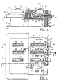
figure 1 est une vue latérale en élévation d'un connecteur réalisé conformément aux enseignements de l'invention ; - la
figure 2 est une vue de dessus du connecteur illustré à lafigure 1 ; - la
figure 3 est une vue latérale à plus grande échelle et en coupe partielle selon la ligne 3-3 de lafigure 4 , du connecteur illustré auxfigures 1 et 2 ; - la
figure 4 est une vue de dessus du connecteur illustré à lafigure 3 avec arrachement d'une moitié du couvercle du connecteur ; - la
figure 5 est une demi-vue en section selon la ligne 5-5 de la figure ; et - la
figure 6 est une vue similaire à celle de la partie supérieure droite de lafigure 1 qui illustre une variante de réalisation d'un connecteur conforme aux enseignements de l'invention du type comportant des lames de contact en forme d'épingle à cheveux.
- The
figure 1 is a side elevational view of a connector made in accordance with the teachings of the invention; - the
figure 2 is a top view of the connector shown in thefigure 1 ; - the
figure 3 is a lateral view on a larger scale and in partial section along line 3-3 of thefigure 4 , from the connector shown inFigures 1 and 2 ; - the
figure 4 is a top view of the connector shown in thefigure 3 with tearing of one half of the connector cover; - the
figure 5 is a half-view in section along line 5-5 of the figure; and - the
figure 6 is a view similar to that of the upper right of thefigure 1 which illustrates an alternative embodiment of a connector according to the teachings of the invention of the type comprising contact blades in the form of a hairpin.
Le connecteur 10 illustré sur les
Comme on peut le voir sur les figures, le boîtier ou support 12 est pour l'essentiel constitué d'une plaque horizontale 18 qui délimite une face plane 20 et d'une paroi latérale 22 de contour sensiblement rectangulaire.As can be seen in the figures, the housing or
La face supérieure 20 de contour rectangulaire comporte une série de logements 24 formés en creux dans la face supérieure 20 de la plaque 18.The
Dans le mode de réalisation illustré sur les figures, le connecteur présente une symétrie générale de conception par rapport à un plan vertical médian P indiqué sur les
Chaque logement 24 se présente sous la forme d'une encoche à bords ou faces parallèles 26 qui est délimité par un fond de logement 28 qui s'étend dans un plan parallèle à la face plane supérieure 20 du boîtier 12.Each
Chaque logement 24 est conçu pour recevoir un conducteur électrique 16 qui est réalisé dans un matériau conducteur déformable élastiquement.Each
Chaque élément 16 est ainsi réalisé sous la forme d'une lame de contact découpée et pliée.Each
Chaque lame de contact 16 s'étend selon une direction générale longitudinale contenue dans un plan vertical parallèle aux faces parallèles 26 du logement correspondant 24 et perpendiculaire à la face 20 du support 12.Each
Chaque lame de contact 16 comporte une première extrémité incurvée convexe 30 qui est prévue pour coopérer avec une plage correspondante (non représentée) d'une carte à mémoire électronique qui est susceptible d'être introduite, selon une direction I parallèle aux logements 24, dans un dispositif de lecture-écriture (non représenté) équipé d'un connecteur 10 selon l'invention.Each
L'extrémité incurvée de contact 30 de chaque lame 16 se prolonge par un bec 32 sensiblement parallèle à la face plane 20 dont la fonction sera expliquée par la suite.The
Chaque lame de contact 16 comporte également une extrémité de raccordement 34 qui s'étend verticalement, c'est-à-dire selon une direction perpendiculaire à la face supérieure 20, le long de la paroi latérale 22 du support 12 et qui se termine par une patte rabattue à angle droit 36 permettant le raccordement de chaque lame 16 sur une piste d'une plaque à circuit imprimé (non représentée), par exemple selon la technique du report à plat des composants.Each
L'extrémité incurvée de contact 30 et l'extrémité de raccordement 34 sont reliées entre elles par une partie médiane de liaison 38 en forme d'épingle à cheveux.The
La partie médiane de liaison 38 de chaque lame 16 comporte ainsi une première branche 40 qui s'étend selon une direction sensiblement parallèle à la face plane 20 du support 12 et une seconde branche 42 formant un angle aigu par rapport à la première branche 30 et qui sont reliées entre elles par le pli médian 44 en forme de U.The
Ce pli médian 44 est tourné vers le centre du connecteur c'est à dire qu'il est situé sensiblement au droit de la puce de la carte à puce lorsque cette dernière est en position de lecture-écriture.This
Cette disposition géométrique confère au connecteur selon l'invention une très grande compacité et un faible encombrement sur la carte à circuit imprimé sur laquelle il sera monté.This geometric arrangement gives the connector according to the invention a very large compactness and a small footprint on the printed circuit board on which it will be mounted.
En effet, la longueur du connecteur, mesurée parallèlement à la direction longitudinale des lames 16 est la plus réduite possible.Indeed, the length of the connector, measured parallel to the longitudinal direction of the
L'extrémité libre 46 de la première branche 40 se prolonge par l'extrémité de raccordement 34 de la lame 16 tandis que l'extrémité libre de la seconde branche 42 de la partie médiane de liaison 38 se prolonge par l'extrémité incurvée de contact 30.The
L'extrémité libre 46 de la première branche 40 de chaque lame 16 est maintenue encastrée de façon que la partie médiane de liaison 38, et notamment la première branche 40 puisse fléchir élastiquement selon une direction D sensiblement perpendiculaire au plan de la face plane du support 12.The
A cet effet, l'extrémité 46 est pincée entre une portion plane 48 du support 12 parallèle à la face plane 20 de ce dernier, mais décalée verticalement vers le bas par rapport à cette face supérieure 20, et une portion de surface correspondante 50 formée en vis-à-vis dans la face interne 52 du couvercle 14 qui prend appui contre la face supérieure plane 20 du support 12.For this purpose, the
En effet, et comme on peut le voir sur les
Après sertissage à chaud des têtes 58 des plots 54, le couvercle 14 est ainsi maintenu fermement sur le support 12 pour pincer les extrémités 46 des premières branches 44 des parties médianes de liaison 38 des lames 16 pour assurer leur effet d'encastrement dans des logements délimités par des surfaces 48 et 50.After hot crimping of the
Afin de permettre le passage des extrémités incurvées de contact 30 des lames 16 et en partie le passage des secondes branches 42 des parties médianes de liaison 38, le couvercle 14 comporte une série de fentes débouchantes 60 alignées en regard des logements 24 et des lames 16.In order to allow the passage of the curved contact ends 30 of the
Dans le mode de réalisation illustré sur les
Préalablement à la mise en place du couvercle 14, chaque lame de contact 16 est mise en place dans le support 12 par introduction latérale, c'est-à-dire sensiblement selon une direction parallèle à la direction d'introduction I.Prior to the introduction of the
Au cours de cette introduction latérale, une patte latérale d'accrochage en forme de harpon 62 de chaque lame de contact 16 est introduite à force dans une fente correspondante 64 du support 12.During this lateral introduction, a harpoon-shaped hooking
Chaque patte d'accrochage 62 s'étend sensiblement parallèlement à la branche 40 de la partie médiane de liaison 38 à laquelle elle est reliée par une traverse 65.Each hooking
Chaque fente 64 est délimitée vers le haut par un pont transversal 66 réalisé venu de moulage avec le support 12 comme on peut le voir sur la
Chaque patte d'accrochage 62 comporte un talon en saillie 68 qui s'étend latéralement vers l'extérieur au-delà de l'extrémité de raccordement 34 de la lame 16 en regard d'une face interne 70 d'une collerette périphérique 72 du couvercle 14 qui s'oppose ainsi à tout échappement latéral accidentel de la lame de contact 16.Each
En position montée, et comme on peut le voir notamment sur la
Le couvercle 14 maintient ainsi toutes les lames 16 légèrement en précontrainte élastique dans une position géométrique précise.The
Cette conception a pour avantage de permettre de faire varier la force d'appui des contacts sur les plots de la carte à mémoire en fonction de la géométrie exact du pliage de la partie médiane de liaison 38, tout en assurant une cote précise de dépassement de la partie de contact incurvée 30 par rapport à la face supérieure 76 du couvercle 14 du connecteur 10.This design has the advantage of making it possible to vary the contact force of the contacts on the pads of the memory card as a function of the exact geometry of the folding of the middle portion of
Le connecteur 10 qui vient d'être décrit présente ainsi une très grande compacité tout en assurant des performances optimales de contact électrique des lames 16 sur les plots d'une carte introduite dans un dispositif de lecture-écriture équipé d'un connecteur selon l'invention.The
La mise en place et la fixation des lames 16 dans le support 12 est assurée mécaniquement par verrouillage des pattes d'accrochage en forme de harpon 62 lors de l'assemblage mécanique des lames 16 dans le support ou boîtier 12 moulé préalablement.The establishment and fixing of the
On décrira maintenant la variante de réalisation illustrée sur la
Sur la
Cette épaisseur réduite accroît la capacité de déformation élastique de chaque lame de contact et permet d'augmenter la course de fléchissement de chaque lame de contact, et ceci malgré la hauteur totale particulièrement réduite du connecteur.This reduced thickness increases the elastic deformation capacity of each contact blade and increases the deflection stroke of each contact blade, despite the particularly small total height of the connector.
Pour augmenter encore la course de fléchissement de chaque lame de contact 16, il est possible de prévoir un trou ( non représenté) dans la portion encastrée 46 de la lame, ce trou recevant l'extrémité libre du bec 32 lorsque la lame est en position fléchie.To further increase the deflection stroke of each
L'amincissement du tronçon intermédiaire de chaque lame est réalisé par écrasement local, avant la découpe des lames. Ce mode d'obtention de l'amincissement "e" permet d'accroître les caractéristiques mécaniques du matériau dans la zone écrouie par l'écrasement.Thinning of the intermediate section of each blade is achieved by local crushing, before cutting the blades. This mode of obtaining the thinning "e" makes it possible to increase the mechanical characteristics of the material in the zone hardened by crushing.
Dans ces différentes variantes de réalisation on remarque que la conception du corps en matériau isolant 12 avec un fond 18 et des faces parallèles 26 pour délimiter les logements 24 qui reçoivent les lames de contact 12 est particulièrement avantageuse en ce qu'elle procure une très bonne isolation électrique des contacts l'un par rapport à l'autre. cette isolation est complétée par la conception complémentaire des fentes 60 du couvercle 14.In these various embodiments it is noted that the design of the body of insulating
De plus, en présence d'une carte en position d'utilisation, tous les logements 24 sont fermés de manière quasi étanche, toute pénétration de poussière ou de tout autre corps étranger dans les alvéoles 24 étant ainsi évitée.In addition, in the presence of a card in the use position, all the
Dans ces modes de réalisation du type à lames de contact en "épingles à cheveux", on remarque que les boucles ou plis médians 44 des lames de contact 16 sont tournées vers le " centre" du connecteur, c'est-à-dire vers le plan médian P qui, lorsqu'une carte est en position d'utilisation, s'étend sensiblement au droit du centre de plages de contact de la carte à microcircuit.In these "hairpin" contact blade type embodiments, it is noted that the middle loops or plies 44 of the
Cette conception géométrique permet de conférer au connecteur une très petite longueur hors tout (mesurée dans le sens de la largeur en considérant la
Sans sortir du cadre de l'invention, le connecteur qui vient d'être décrit peut être utilisé dans un dispositif de lecture-écriture dans lequel la carte à mémoire électronique se déplace, par rapport au connecteur, selon une direction perpendiculaire à son plan général et perpendiculaire au plan de la face 20.Without departing from the scope of the invention, the connector which has just been described can be used in a read-write device in which the electronic memory card moves, with respect to the connector, in a direction perpendicular to its general plane and perpendicular to the plane of the
Dans une telle application, la conception des lames de contact 16 permet d'obtenir un effet d'auto-nettoyage du fait de la coopération des extrémités incurvées 30 avec les pistes conductrices de la carte lors de la phase finale d'atterrissage de cette dernière.In such an application, the design of the
Claims (11)
- Electrical connector (10) for the connection of a microcircuit electronic memory card, including, on one of its main faces, a plurality of aligned electrical contact pads, the connector including a support (12) made of insulating material having a plane face (20) parallel to the direction of insertion (I) of the card into a read/write device and two series of electrical conductors (16) in the form of elastically deformable blades (16) which extend parallel to the direction (I) of insertion of the card and which are aligned by pairs longitudinally, each contact blade (16) comprising a first incurvate end (30) for contacting one of the pads on the card, projecting from the plane of the plane face (20) of the support (12), a central portion (38) for connecting the blade (16) of the support (12) and a second end (34) for connection of the blade (16) to a processing circuit of the read/write device of the type in which the central connecting part (38) of each blade (16) is a part folded over into the shape of a hairpin extending substantially parallel to the plane face (20) of the support (12), including a first branch (40) whose free end (46) is extended by the connection end (34) of the blade (16) and which comprises means (62) for fixing blade (16) to the support (12), and including a second branch (42) whose free end is extended by the incurvate contacting end (30) of the blade (16), the first (40) and the second (42) branches being connected together by a U-shaped central fold (44), characterized in that the central fold (44) is turned toward the median plane (P) of the connector which extends substantially in line with the centre of the contact pads of the microcircuit card when the latter is in its read/write position, and in that the first branch (40) can bend in a direction (D) substantially perpendicular to the plane of said plane face (20) of the support (12).
- Electrical connector according to claim 1, characterized in that the free end (46) of the first branch (40) of the central connecting part (38) of the blade (16) is embedded in a housing in the support, and in that the first branch (40) extends opposite a housing (24) formed facingly in the plane face (20) of the support (12) in order to permit bending of the first branch (40) in a direction substantially perpendicular to the plane face (20) of the support (12).
- Electrical connector according to claim 2, characterized in that the incurvate contacting end (30) of each blade (16) extends substantially in line with the embedded free end (46) of the first branch (40) of the central connecting part of the blade (16).
- Electrical connector according to one of claims 2 or 3, characterized in that the housing (24), opposite which the first branch (40) of the central connecting part (38) of the blade (16) extends, includes a bottom (28) which limits the bending of the first branch (40).
- Electrical connector according to any one of the preceding claims, characterized in that the incurvate contacting end (30) of each blade (16) is extended by a nose (32) which is elastically urged so as to bear against a stop surface (74).
- Electrical connector according to any one of the preceding claims, characterized in that it includes a cover (14) made of insulating material, which bears on the plane face (20) of the support (12) and which includes a series of parallel slots (60) through each of which an incurvate contacting end (30) of a blade (16) projects.
- Electrical connector according to claim 6, taken in combination with claim 5, characterized in that the stop surface (74) is formed facingly in the internal face (52) of the cover (14) which extends opposite the plane face (20) of the support (12).
- Electrical connector according to any one of the preceding claims, characterized in that the connection end (34) of each blade (16) extends in a direction perpendicular to the plane of the plane face (20) of the support (12) going away from the second branch (40) of the central connecting part (38) of the blade (16) and along a lateral face (22) of the support (12).
- Electrical connector according to any one of the preceding claims, characterized in that each contact blade (16) is produced in the form of a cut-out and folded metal strip of substantially constant thickness, and in that each contact strip includes an intermediate section of reduced thickness (e), produced especially by compression, which extends between the contacting and connection ends of the blade.
- Electrical connector according to claim 9, characterized in that the section of reduced thickness (e) extends between the free end (46) of the first branch and the free end of the second branch (42).
- Electrical connector according to any one of the preceding claims, characterized in that the incurvate contacting end (30) is located longitudinally between the central fold, which connects together the first (40) and second (42) branches of the central connecting part and the connection end (34).
Priority Applications (1)
| Application Number | Priority Date | Filing Date | Title |
|---|---|---|---|
| DE69433825T DE69433825T3 (en) | 1993-12-24 | 1994-12-26 | Space-saving electrical connector for an IC memory card |
Applications Claiming Priority (3)
| Application Number | Priority Date | Filing Date | Title |
|---|---|---|---|
| FR9315633 | 1993-12-24 | ||
| FR9315633A FR2714539B1 (en) | 1993-12-24 | 1993-12-24 | Electrical connector for the connection of an electronic memory card. |
| EP95905168A EP0686289B1 (en) | 1993-12-24 | 1994-12-26 | Electric connector for connecting an electronic memory card |
Related Parent Applications (2)
| Application Number | Title | Priority Date | Filing Date |
|---|---|---|---|
| EP95905168A Division EP0686289B1 (en) | 1993-12-24 | 1994-12-26 | Electric connector for connecting an electronic memory card |
| EP95905168.1 Division | 1995-07-06 |
Publications (4)
| Publication Number | Publication Date |
|---|---|
| EP0803835A2 EP0803835A2 (en) | 1997-10-29 |
| EP0803835A3 EP0803835A3 (en) | 2000-11-02 |
| EP0803835B1 EP0803835B1 (en) | 2004-06-02 |
| EP0803835B2 true EP0803835B2 (en) | 2012-09-12 |
Family
ID=9454385
Family Applications (3)
| Application Number | Title | Priority Date | Filing Date |
|---|---|---|---|
| EP97201929A Expired - Lifetime EP0803835B2 (en) | 1993-12-24 | 1994-12-26 | Space saving electric connector for an IC memory card |
| EP98201350A Expired - Lifetime EP0860792B1 (en) | 1993-12-24 | 1994-12-26 | Electrical connector for electronic memory card |
| EP95905168A Expired - Lifetime EP0686289B1 (en) | 1993-12-24 | 1994-12-26 | Electric connector for connecting an electronic memory card |
Family Applications After (2)
| Application Number | Title | Priority Date | Filing Date |
|---|---|---|---|
| EP98201350A Expired - Lifetime EP0860792B1 (en) | 1993-12-24 | 1994-12-26 | Electrical connector for electronic memory card |
| EP95905168A Expired - Lifetime EP0686289B1 (en) | 1993-12-24 | 1994-12-26 | Electric connector for connecting an electronic memory card |
Country Status (9)
| Country | Link |
|---|---|
| US (1) | US5980323A (en) |
| EP (3) | EP0803835B2 (en) |
| JP (3) | JP2878457B2 (en) |
| KR (2) | KR100262806B1 (en) |
| CN (3) | CN1049320C (en) |
| DE (3) | DE69419406T2 (en) |
| ES (3) | ES2217365T3 (en) |
| FR (1) | FR2714539B1 (en) |
| WO (1) | WO1995018421A1 (en) |
Families Citing this family (59)
| Publication number | Priority date | Publication date | Assignee | Title |
|---|---|---|---|---|
| FR2720864B1 (en) | 1994-06-01 | 1996-07-05 | Itt Composants Instr | Electrical connector for the connection of an electronic memory card comprising an integrated switch for detecting the presence of a card. |
| FR2720869B1 (en) * | 1994-06-01 | 1996-07-12 | Itt Composants Instr | Advanced electrical connector for connecting an electronic memory card. |
| FR2726694B1 (en) * | 1994-11-07 | 1996-12-06 | Itt Composants Instr | ELECTRICAL CONNECTOR FOR AN ELECTRONIC MEMORY CARD COMPRISING ELECTRICAL CONNECTION MEANS OF THE INSULATOR DISPLACEMENT TYPE |
| FR2733358B1 (en) * | 1995-04-21 | 1997-05-30 | Itt Composants Instr | ELECTRICAL CONNECTOR, PARTICULARLY FOR CONNECTING AN ELECTRONIC MEMORY CARD |
| GB9513540D0 (en) * | 1995-07-04 | 1995-09-06 | Elco Europ Ltd | Electrical connectors |
| FR2737352B1 (en) * | 1995-07-28 | 1997-08-29 | Itt Composants Instr | ELECTRICAL CONNECTOR FOR CONNECTION OF A CARD WITH AN INTEGRATED CIRCUIT (S) WITH CONTACT |
| JP3720373B2 (en) * | 1996-02-29 | 2005-11-24 | ザ ウィタカー コーポレーション | Device for electrically connecting a chip card to a printed circuit board |
| DE19608990A1 (en) * | 1996-03-08 | 1997-09-11 | Bosch Gmbh Robert | Chip card and card reader for chip cards |
| US6315620B1 (en) * | 1997-04-24 | 2001-11-13 | Seagate Technology Llc | System, method, and device for a pre-loaded straddle mounted connector assembly |
| US6326568B2 (en) | 1997-07-02 | 2001-12-04 | Molex Incorporated | Blade switch assembly for a card reader |
| FR2773275B1 (en) * | 1997-12-26 | 2000-01-28 | Itt Mfg Enterprises Inc | VERY LOW THICKNESS ELECTRICAL CONNECTOR FOR CONNECTION OF AN ELECTRONIC MEMORY CARD |
| DE19825808B4 (en) * | 1998-06-09 | 2006-10-26 | Amphenol-Tuchel Electronics Gmbh | Contact element for chip card contacting device |
| DE19829551C2 (en) * | 1998-07-02 | 2000-12-14 | Amphenol Tuchel Elect | Contact carrier |
| FI991002L (en) * | 1999-05-03 | 2000-11-04 | Nokia Mobile Phones Ltd | Smart card slot and mobile station |
| FR2793353B1 (en) * | 1999-05-07 | 2001-06-01 | Itt Mfg Enterprises Inc | MONOBLOCK ELECTRICAL CONNECTOR FOR THE CONNECTION OF AN INTEGRATED CIRCUIT (S) CARD |
| JP3050871B1 (en) * | 1999-05-26 | 2000-06-12 | 山一電機株式会社 | Bottom contact type contact |
| US6099356A (en) * | 1999-07-19 | 2000-08-08 | Hon Hai Precision Ind. Co., Ltd. | Compression connector |
| TW429652B (en) * | 1999-12-23 | 2001-04-11 | Hon Hai Prec Ind Co Ltd | Electric connector terminal |
| TW515592U (en) * | 2000-01-20 | 2002-12-21 | Hon Hai Prec Ind Co Ltd | Electrical connector |
| US6276941B1 (en) * | 2000-02-22 | 2001-08-21 | Hon Hai Precision Ind. Co., Ltd. | Board to board connector |
| US6758702B2 (en) * | 2000-02-24 | 2004-07-06 | Fci Americas Technology, Inc. | Electrical connector with compression contacts |
| TW438125U (en) * | 2000-03-03 | 2001-05-28 | Hon Hai Prec Ind Co Ltd | Electrical connector |
| US6855013B2 (en) * | 2000-05-08 | 2005-02-15 | Tyco Electronic Logistics Ag | LCD connector for printed circuit boards |
| DE10027600C1 (en) * | 2000-06-02 | 2001-11-22 | Amphenol Tuchel Elect | Contact for mounting in contact bearer has movable part with protruding curved section joined to intermediate section and to hooked section fitting in guide part opening in loaded state |
| FR2813446B1 (en) * | 2000-08-31 | 2006-12-01 | Schlumberger Systems & Service | ELECTRONIC APPARATUS COMPRISING AN ELECTRICAL CONNECTOR HAVING A TWO-BLINK CONTACT SPRING |
| TW529208B (en) * | 2000-10-13 | 2003-04-21 | Jst Mfg Co Ltd | Electric connector and electric connector with cap |
| JP3912723B2 (en) * | 2001-04-19 | 2007-05-09 | 日本圧着端子製造株式会社 | PGA socket |
| JP4841756B2 (en) * | 2001-06-08 | 2011-12-21 | 日本圧着端子製造株式会社 | Contact and electrical connector with this |
| SG99960A1 (en) * | 2001-11-23 | 2003-11-27 | Fci Asia Technology Pte Ltd | Electrical connector |
| JP4441157B2 (en) * | 2002-01-28 | 2010-03-31 | パナソニック電工株式会社 | connector |
| US6860766B2 (en) | 2002-03-08 | 2005-03-01 | Cinch Connectors, Inc. | Electrical connector |
| TW540838U (en) * | 2002-05-22 | 2003-07-01 | Benq Corp | Electrical connector and mobile phone using the same |
| TW549629U (en) * | 2002-06-25 | 2003-08-21 | Molex Inc | Electrical connector |
| FR2843654B1 (en) * | 2002-08-13 | 2006-03-03 | Itt Mfg Entpr S Inc | ARRANGEMENT FOR THE ELECTRICAL CONNECTION OF A COMPONENT ON THE TOP SIDE OF A PLATE WITH CIRCUIT BOARDS |
| DE10238661B3 (en) * | 2002-08-23 | 2004-02-26 | Lumberg Connect Gmbh & Co. Kg | Electrical contacting device, in particular for connecting a voltage source to an electronic circuit |
| SG118181A1 (en) * | 2003-03-25 | 2006-01-27 | Fci Asia Technology Pte Ltd | High density electrical connector |
| US6921270B2 (en) * | 2003-06-11 | 2005-07-26 | Cinch Connectors, Inc. | Electrical connector |
| US7625216B2 (en) * | 2003-06-11 | 2009-12-01 | Cinch Connectors, Inc. | Electrical connector |
| US7455556B2 (en) * | 2003-06-11 | 2008-11-25 | Cinch Connectors, Inc. | Electrical contact |
| US7674143B2 (en) * | 2003-09-17 | 2010-03-09 | Ngk Spark Plug Co., Ltd. | Sensor and method of producing sensor |
| JP4307344B2 (en) * | 2004-07-20 | 2009-08-05 | シチズン電子株式会社 | Surface mount module |
| US6955572B1 (en) * | 2004-07-22 | 2005-10-18 | Hon Hai Precision Ind. Co., Ltd | LGA contact with extended arm for IC connector |
| TWM280586U (en) * | 2005-04-01 | 2005-11-11 | Hon Hai Prec Ind Co Ltd | Electrical card connector |
| EP1736909B1 (en) * | 2005-06-23 | 2008-05-07 | ddm hopt + schuler GmbH & Co. KG. | Cardreader with dual U-shaped spring contacts |
| DE502005002999D1 (en) | 2005-06-23 | 2008-04-10 | Hopt & Schuler Ddm | Card reader with symmetrical contact spring |
| FI120069B (en) * | 2006-10-20 | 2009-06-15 | Perlos Oyj | Board-to-board connectors and arrangements in conjunction with two PCBs |
| CN101212095B (en) * | 2006-12-26 | 2012-01-11 | 富士康(昆山)电脑接插件有限公司 | Electric connector terminal |
| GB2445380B (en) * | 2007-01-04 | 2009-12-02 | Motorola Inc | Electrical connector and connector module |
| JP5238928B2 (en) * | 2007-04-19 | 2013-07-17 | 並木精密宝石株式会社 | Feed terminal structure |
| KR101005767B1 (en) | 2008-06-24 | 2011-01-06 | 주식회사 이엠따블유 | Pin for electrical connection |
| JP2010073341A (en) * | 2008-09-16 | 2010-04-02 | Kitagawa Ind Co Ltd | Surface-mounted contact |
| US9804337B2 (en) | 2010-02-12 | 2017-10-31 | Commscope Technologies Llc | Managed fiber connectivity systems |
| SG176335A1 (en) | 2010-05-27 | 2011-12-29 | Molex Singapore Pte Ltd | Electronic card connector |
| US8079851B1 (en) * | 2010-11-11 | 2011-12-20 | Hon Hai Precision Ind. Co., Ltd. | Socket with lower contact |
| FR2968466B1 (en) | 2010-12-07 | 2013-10-25 | Injection Haute Prec | CONTACT AND MICROCIRCUIT BOARD CONNECTOR |
| JP6025194B2 (en) * | 2012-11-12 | 2016-11-16 | 北川工業株式会社 | contact |
| JP6941000B2 (en) * | 2017-08-09 | 2021-09-29 | ヒロセ電機株式会社 | Electrical connector for circuit board and its manufacturing method |
| TWM602744U (en) * | 2020-01-20 | 2020-10-11 | 唐虞企業股份有限公司 | Forced mechanism and connector constituted of the same |
| CN115732967A (en) * | 2022-11-29 | 2023-03-03 | 昆山宏泽电子有限公司 | Solder-free electrical connector |
Citations (5)
| Publication number | Priority date | Publication date | Assignee | Title |
|---|---|---|---|---|
| GB1030676A (en) † | 1961-12-12 | 1966-05-25 | Burndy Corp | Assemblies of components on printed circuit boards |
| US3771109A (en) † | 1972-05-01 | 1973-11-06 | Bunker Ramo | Electrical connector for integrated circuit device |
| US4553192A (en) † | 1983-08-25 | 1985-11-12 | International Business Machines Corporation | High density planar interconnected integrated circuit package |
| DE8529580U1 (en) † | 1985-10-18 | 1986-01-09 | Preh, Elektrofeinmechanische Werke Jakob Preh Nachf. Gmbh & Co, 8740 Bad Neustadt | Device for evaluating an information carrier card |
| FR2587549A1 (en) † | 1985-09-13 | 1987-03-20 | Radiotechnique | Interconnection system |
Family Cites Families (18)
| Publication number | Priority date | Publication date | Assignee | Title |
|---|---|---|---|---|
| JPS6111284U (en) * | 1984-06-26 | 1986-01-23 | 沖電線株式会社 | Board connection connector |
| DE3602668A1 (en) * | 1986-01-29 | 1987-07-30 | Allied Corp | CONTACT DEVICE FOR A CHIP CARD |
| JPH0326628Y2 (en) * | 1986-06-24 | 1991-06-10 | ||
| GB2214680B (en) * | 1988-01-19 | 1991-07-31 | Technophone Ltd | Card reader |
| KR910001533A (en) * | 1988-06-30 | 1991-01-31 | 아오이 죠이치 | IC card reading / recording device |
| FR2638293B1 (en) * | 1988-10-26 | 1991-01-18 | Itt Composants Instr | ELECTRICAL CONNECTOR FOR ELECTRONIC MEMORY CARDS, METHOD FOR PRODUCING SUCH A CONNECTOR AND READ-WRITE DEVICE INCLUDING SUCH A CONNECTOR |
| DE8908801U1 (en) * | 1989-07-19 | 1989-09-07 | Siemens AG, 1000 Berlin und 8000 München | Card reader with a slide that can be moved in a holder against spring force |
| EP0444396B2 (en) * | 1990-01-30 | 2000-11-02 | AMPHENOL-TUCHEL ELECTRONICS GmbH | Connection device for a Si-module |
| NL9001061A (en) * | 1990-05-03 | 1991-12-02 | Philips Nv | APPARATUS CONTAINING A PLASTIC HOUSING WITH CHANNELS FOR ATTACHING CONTACT AGENTS. |
| DE69104350T2 (en) * | 1991-06-28 | 1995-02-16 | Molex Inc | IC card connector. |
| JPH05114444A (en) * | 1991-10-14 | 1993-05-07 | Minnesota Mining & Mfg Co <3M> | Connector having press-fit type probe |
| JP2598581Y2 (en) * | 1991-12-03 | 1999-08-16 | 矢崎総業株式会社 | connector |
| US5154644A (en) * | 1992-01-15 | 1992-10-13 | Molex Incorporated | Edge connector for a printed circuit card |
| JP2761489B2 (en) * | 1992-04-06 | 1998-06-04 | モレックス インコーポレーテッド | Electrical connector |
| IE80506B1 (en) * | 1992-05-08 | 1998-08-26 | Molex Inc | Electrical connector with contact anti-overstress means |
| US5425651A (en) * | 1994-03-04 | 1995-06-20 | The Whitaker Corporation | Card edge connector providing non-simultaneous electrical connections |
| FR2726694B1 (en) * | 1994-11-07 | 1996-12-06 | Itt Composants Instr | ELECTRICAL CONNECTOR FOR AN ELECTRONIC MEMORY CARD COMPRISING ELECTRICAL CONNECTION MEANS OF THE INSULATOR DISPLACEMENT TYPE |
| FR2737352B1 (en) * | 1995-07-28 | 1997-08-29 | Itt Composants Instr | ELECTRICAL CONNECTOR FOR CONNECTION OF A CARD WITH AN INTEGRATED CIRCUIT (S) WITH CONTACT |
-
1993
- 1993-12-24 FR FR9315633A patent/FR2714539B1/en not_active Expired - Fee Related
-
1994
- 1994-12-26 CN CN94191281A patent/CN1049320C/en not_active Expired - Fee Related
- 1994-12-26 WO PCT/FR1994/001532 patent/WO1995018421A1/en not_active Ceased
- 1994-12-26 JP JP7517814A patent/JP2878457B2/en not_active Expired - Lifetime
- 1994-12-26 ES ES97201929T patent/ES2217365T3/en not_active Expired - Lifetime
- 1994-12-26 KR KR1019970704124A patent/KR100262806B1/en not_active Expired - Fee Related
- 1994-12-26 EP EP97201929A patent/EP0803835B2/en not_active Expired - Lifetime
- 1994-12-26 ES ES98201350T patent/ES2227764T3/en not_active Expired - Lifetime
- 1994-12-26 EP EP98201350A patent/EP0860792B1/en not_active Expired - Lifetime
- 1994-12-26 DE DE69419406T patent/DE69419406T2/en not_active Expired - Lifetime
- 1994-12-26 CN CNB971146462A patent/CN1160652C/en not_active Expired - Fee Related
- 1994-12-26 DE DE69433825T patent/DE69433825T3/en not_active Expired - Lifetime
- 1994-12-26 KR KR1019950703583A patent/KR100242733B1/en not_active Expired - Lifetime
- 1994-12-26 DE DE69434153T patent/DE69434153T2/en not_active Expired - Lifetime
- 1994-12-26 ES ES95905168T patent/ES2135692T3/en not_active Expired - Lifetime
- 1994-12-26 EP EP95905168A patent/EP0686289B1/en not_active Expired - Lifetime
-
1997
- 1997-07-07 US US08/888,435 patent/US5980323A/en not_active Expired - Lifetime
- 1997-07-11 JP JP18640897A patent/JP3195567B2/en not_active Expired - Lifetime
-
1998
- 1998-04-16 CN CN98106940A patent/CN1124561C/en not_active Expired - Fee Related
- 1998-06-24 JP JP17756698A patent/JP3443001B2/en not_active Expired - Lifetime
Patent Citations (5)
| Publication number | Priority date | Publication date | Assignee | Title |
|---|---|---|---|---|
| GB1030676A (en) † | 1961-12-12 | 1966-05-25 | Burndy Corp | Assemblies of components on printed circuit boards |
| US3771109A (en) † | 1972-05-01 | 1973-11-06 | Bunker Ramo | Electrical connector for integrated circuit device |
| US4553192A (en) † | 1983-08-25 | 1985-11-12 | International Business Machines Corporation | High density planar interconnected integrated circuit package |
| FR2587549A1 (en) † | 1985-09-13 | 1987-03-20 | Radiotechnique | Interconnection system |
| DE8529580U1 (en) † | 1985-10-18 | 1986-01-09 | Preh, Elektrofeinmechanische Werke Jakob Preh Nachf. Gmbh & Co, 8740 Bad Neustadt | Device for evaluating an information carrier card |
Also Published As
Similar Documents
| Publication | Publication Date | Title |
|---|---|---|
| EP0803835B2 (en) | Space saving electric connector for an IC memory card | |
| EP0756355A1 (en) | Electrical connector for connecting to the contacts of an integrated printed circuit | |
| EP0366513B1 (en) | Electrical connector for electronic memory cards, process for producing such a connector and read-write device incorporating such a connector | |
| EP0766875B1 (en) | Electrical connector, in particular for connecting an electronic memory card | |
| EP0738429B1 (en) | Electrical connector for an electronic smart card comprising insulator moving type electrical connection means | |
| EP1193802B1 (en) | Spring connector for connecting a display to a printed circuit board | |
| FR2821988A1 (en) | ELECTRICAL CONNECTOR FOR ELECTRONIC MEMORY CARDS WITH LARGE STORAGE CAPACITY | |
| EP1050018A2 (en) | Integrated circuit contact card, comprising a detachable minicard | |
| EP0316700A1 (en) | Contact frame for an IC card reader | |
| FR2803110A1 (en) | CONNECTOR FOR A MICROCIRCUIT CARD AND METHOD FOR MOUNTING SUCH A CARD IN THE CONNECTOR | |
| FR2771846A1 (en) | MULTI-WAY TACTILE ELECTRICAL SWITCH WITH SINGLE-TRIGGER DEVICE | |
| EP0711438B1 (en) | Electric connector for connecting an electronic smart card including a built-in switch for detecting the presence of a card | |
| EP0660253B1 (en) | Strip of contacts and connector comprising the same | |
| EP0981798B1 (en) | Sliding contact connector for connecting a card with microcircuits | |
| FR2773244A1 (en) | SWITCH FOR DETECTING THE PRESENCE OF AN ELECTRONIC MEMORY CARD IN A READ-WRITE DEVICE | |
| WO2004066450A1 (en) | Plug connector equipped with compression contact terminals | |
| FR2636173A1 (en) | ARMORED CONNECTOR HOUSING | |
| FR2773246A1 (en) | MINIATURIZED ELECTRIC SWITCH, INTEGRATED WITH A CONNECTOR, FOR DETECTION OF THE PRESENCE OF AN ELECTRONIC MEMORY CARD | |
| EP0656597B1 (en) | Card contact frame and connector | |
| EP0822507B1 (en) | Support plate detector and connector having such a detector | |
| EP0711440B1 (en) | Electric connector for connecting an electronic smart card | |
| FR2843654A1 (en) | Electrical connector for mounting on circuit board, has laterally spaced columns of contacts, and termination ends of contacts in two columns lie in single longitudinally-extending row | |
| FR2658364A1 (en) | Electrical connector for electronic-memory cards | |
| EP0656598A1 (en) | Contact frame and connector for card | |
| FR2843837A1 (en) | Thin electrical connector used to connect an integrated circuit card to contacts, has U-shaped contact blade having intermediary arm supported by the insulated support |
Legal Events
| Date | Code | Title | Description |
|---|---|---|---|
| PUAI | Public reference made under article 153(3) epc to a published international application that has entered the european phase |
Free format text: ORIGINAL CODE: 0009012 |
|
| AC | Divisional application: reference to earlier application |
Ref document number: 686289 Country of ref document: EP |
|
| AK | Designated contracting states |
Kind code of ref document: A2 Designated state(s): DE ES FR GB IT SE |
|
| PUAL | Search report despatched |
Free format text: ORIGINAL CODE: 0009013 |
|
| AK | Designated contracting states |
Kind code of ref document: A3 Designated state(s): DE ES FR GB IT SE |
|
| RIC1 | Information provided on ipc code assigned before grant |
Free format text: 7G 06K 7/06 A, 7G 06K 7/00 B |
|
| 17P | Request for examination filed |
Effective date: 20010208 |
|
| 17Q | First examination report despatched |
Effective date: 20021011 |
|
| RAP1 | Party data changed (applicant data changed or rights of an application transferred) |
Owner name: ITT MANUFACTURING ENTERPRISES, INC. |
|
| GRAP | Despatch of communication of intention to grant a patent |
Free format text: ORIGINAL CODE: EPIDOSNIGR1 |
|
| GRAS | Grant fee paid |
Free format text: ORIGINAL CODE: EPIDOSNIGR3 |
|
| GRAA | (expected) grant |
Free format text: ORIGINAL CODE: 0009210 |
|
| AC | Divisional application: reference to earlier application |
Ref document number: 0686289 Country of ref document: EP Kind code of ref document: P |
|
| AK | Designated contracting states |
Kind code of ref document: B1 Designated state(s): DE ES FR GB IT SE |
|
| PG25 | Lapsed in a contracting state [announced via postgrant information from national office to epo] |
Ref country code: IT Free format text: LAPSE BECAUSE OF FAILURE TO SUBMIT A TRANSLATION OF THE DESCRIPTION OR TO PAY THE FEE WITHIN THE PRESCRIBED TIME-LIMIT;WARNING: LAPSES OF ITALIAN PATENTS WITH EFFECTIVE DATE BEFORE 2007 MAY HAVE OCCURRED AT ANY TIME BEFORE 2007. THE CORRECT EFFECTIVE DATE MAY BE DIFFERENT FROM THE ONE RECORDED. Effective date: 20040602 |
|
| REG | Reference to a national code |
Ref country code: GB Ref legal event code: FG4D Free format text: NOT ENGLISH |
|
| REF | Corresponds to: |
Ref document number: 69433825 Country of ref document: DE Date of ref document: 20040708 Kind code of ref document: P |
|
| REG | Reference to a national code |
Ref country code: SE Ref legal event code: TRGR |
|
| GBT | Gb: translation of ep patent filed (gb section 77(6)(a)/1977) |
Effective date: 20040826 |
|
| REG | Reference to a national code |
Ref country code: ES Ref legal event code: FG2A Ref document number: 2217365 Country of ref document: ES Kind code of ref document: T3 |
|
| PGFP | Annual fee paid to national office [announced via postgrant information from national office to epo] |
Ref country code: SE Payment date: 20041221 Year of fee payment: 11 |
|
| PGFP | Annual fee paid to national office [announced via postgrant information from national office to epo] |
Ref country code: ES Payment date: 20050110 Year of fee payment: 11 |
|
| PLAQ | Examination of admissibility of opposition: information related to despatch of communication + time limit deleted |
Free format text: ORIGINAL CODE: EPIDOSDOPE2 |
|
| PLBQ | Unpublished change to opponent data |
Free format text: ORIGINAL CODE: EPIDOS OPPO |
|
| PLAQ | Examination of admissibility of opposition: information related to despatch of communication + time limit deleted |
Free format text: ORIGINAL CODE: EPIDOSDOPE2 |
|
| PLBQ | Unpublished change to opponent data |
Free format text: ORIGINAL CODE: EPIDOS OPPO |
|
| PLBI | Opposition filed |
Free format text: ORIGINAL CODE: 0009260 |
|
| PLAQ | Examination of admissibility of opposition: information related to despatch of communication + time limit deleted |
Free format text: ORIGINAL CODE: EPIDOSDOPE2 |
|
| PLAR | Examination of admissibility of opposition: information related to receipt of reply deleted |
Free format text: ORIGINAL CODE: EPIDOSDOPE4 |
|
| PLBQ | Unpublished change to opponent data |
Free format text: ORIGINAL CODE: EPIDOS OPPO |
|
| PLAB | Opposition data, opponent's data or that of the opponent's representative modified |
Free format text: ORIGINAL CODE: 0009299OPPO |
|
| PLAX | Notice of opposition and request to file observation + time limit sent |
Free format text: ORIGINAL CODE: EPIDOSNOBS2 |
|
| 26 | Opposition filed |
Opponent name: THE WHITAKER CORPORATION Effective date: 20050301 Opponent name: DDM HOPT & SCHULER GMBH & CO. KG Effective date: 20050225 |
|
| R26 | Opposition filed (corrected) |
Opponent name: THE WHITAKER CORPORATION Effective date: 20050301 Opponent name: DDM HOPT & SCHULER GMBH & CO. KG Effective date: 20050225 |
|
| PLAF | Information modified related to communication of a notice of opposition and request to file observations + time limit |
Free format text: ORIGINAL CODE: EPIDOSCOBS2 |
|
| PLBB | Reply of patent proprietor to notice(s) of opposition received |
Free format text: ORIGINAL CODE: EPIDOSNOBS3 |
|
| PG25 | Lapsed in a contracting state [announced via postgrant information from national office to epo] |
Ref country code: SE Free format text: LAPSE BECAUSE OF NON-PAYMENT OF DUE FEES Effective date: 20051227 Ref country code: ES Free format text: LAPSE BECAUSE OF NON-PAYMENT OF DUE FEES Effective date: 20051227 |
|
| EUG | Se: european patent has lapsed | ||
| REG | Reference to a national code |
Ref country code: ES Ref legal event code: FD2A Effective date: 20051227 |
|
| RAP2 | Party data changed (patent owner data changed or rights of a patent transferred) |
Owner name: COACTIVE TECHNOLOGIES, INC. |
|
| REG | Reference to a national code |
Ref country code: GB Ref legal event code: 732E |
|
| APBP | Date of receipt of notice of appeal recorded |
Free format text: ORIGINAL CODE: EPIDOSNNOA2O |
|
| APAH | Appeal reference modified |
Free format text: ORIGINAL CODE: EPIDOSCREFNO |
|
| APBP | Date of receipt of notice of appeal recorded |
Free format text: ORIGINAL CODE: EPIDOSNNOA2O |
|
| REG | Reference to a national code |
Ref country code: FR Ref legal event code: TP |
|
| PLAB | Opposition data, opponent's data or that of the opponent's representative modified |
Free format text: ORIGINAL CODE: 0009299OPPO |
|
| R26 | Opposition filed (corrected) |
Opponent name: THE WHITAKER CORPORATION Effective date: 20050301 Opponent name: DDM HOPT & SCHULER GMBH & CO. KG Effective date: 20050225 |
|
| APBQ | Date of receipt of statement of grounds of appeal recorded |
Free format text: ORIGINAL CODE: EPIDOSNNOA3O |
|
| PLAB | Opposition data, opponent's data or that of the opponent's representative modified |
Free format text: ORIGINAL CODE: 0009299OPPO |
|
| APBU | Appeal procedure closed |
Free format text: ORIGINAL CODE: EPIDOSNNOA9O |
|
| RAP2 | Party data changed (patent owner data changed or rights of a patent transferred) |
Owner name: COACTIVE TECHNOLOGIES, LLC |
|
| REG | Reference to a national code |
Ref country code: DE Ref legal event code: R082 Ref document number: 69433825 Country of ref document: DE Representative=s name: DREISS PATENTANWAELTE, DE |
|
| REG | Reference to a national code |
Ref country code: DE Ref legal event code: R082 Ref document number: 69433825 Country of ref document: DE Representative=s name: DREISS PATENTANWAELTE PARTG MBB, DE Effective date: 20120201 Ref country code: DE Ref legal event code: R082 Ref document number: 69433825 Country of ref document: DE Representative=s name: DREISS PATENTANWAELTE PARTNERSCHAFT, DE Effective date: 20120201 Ref country code: DE Ref legal event code: R081 Ref document number: 69433825 Country of ref document: DE Owner name: COACTIVE TECHNOLOGIES, LLC, NEWTON, US Free format text: FORMER OWNER: COACTIVE TECHNOLOGIES, INC., GREENWICH, CONN., US Effective date: 20120201 Ref country code: DE Ref legal event code: R081 Ref document number: 69433825 Country of ref document: DE Owner name: DELTATECH CONTROLS USA, LLC, US Free format text: FORMER OWNER: COACTIVE TECHNOLOGIES, INC., GREENWICH, US Effective date: 20120201 Ref country code: DE Ref legal event code: R081 Ref document number: 69433825 Country of ref document: DE Owner name: COACTIVE TECHNOLOGIES, LLC, US Free format text: FORMER OWNER: COACTIVE TECHNOLOGIES, INC., GREENWICH, US Effective date: 20120201 |
|
| PUAH | Patent maintained in amended form |
Free format text: ORIGINAL CODE: 0009272 |
|
| STAA | Information on the status of an ep patent application or granted ep patent |
Free format text: STATUS: PATENT MAINTAINED AS AMENDED |
|
| 27A | Patent maintained in amended form |
Effective date: 20120912 |
|
| AK | Designated contracting states |
Kind code of ref document: B2 Designated state(s): DE ES FR GB IT SE |
|
| REG | Reference to a national code |
Ref country code: DE Ref legal event code: R082 Ref document number: 69433825 Country of ref document: DE Representative=s name: DREISS PATENTANWAELTE PARTNERSCHAFT, DE |
|
| REG | Reference to a national code |
Ref country code: DE Ref legal event code: R102 Ref document number: 69433825 Country of ref document: DE Effective date: 20120912 |
|
| REG | Reference to a national code |
Ref country code: DE Ref legal event code: R082 Ref document number: 69433825 Country of ref document: DE Representative=s name: DREISS PATENTANWAELTE PARTNERSCHAFT, DE |
|
| REG | Reference to a national code |
Ref country code: DE Ref legal event code: R082 Ref document number: 69433825 Country of ref document: DE Representative=s name: DREISS PATENTANWAELTE PARTG MBB, DE Effective date: 20121121 Ref country code: DE Ref legal event code: R082 Ref document number: 69433825 Country of ref document: DE Representative=s name: DREISS PATENTANWAELTE PARTG MBB, DE Effective date: 20120919 Ref country code: DE Ref legal event code: R082 Ref document number: 69433825 Country of ref document: DE Representative=s name: DREISS PATENTANWAELTE PARTNERSCHAFT, DE Effective date: 20120919 Ref country code: DE Ref legal event code: R082 Ref document number: 69433825 Country of ref document: DE Representative=s name: DREISS PATENTANWAELTE PARTNERSCHAFT, DE Effective date: 20121121 Ref country code: DE Ref legal event code: R081 Ref document number: 69433825 Country of ref document: DE Owner name: COACTIVE TECHNOLOGIES, LLC, NEWTON, US Free format text: FORMER OWNER: COACTIVE TECHNOLOGIES, LLC, NEWTON, MASS., US Effective date: 20121121 Ref country code: DE Ref legal event code: R081 Ref document number: 69433825 Country of ref document: DE Owner name: DELTATECH CONTROLS USA, LLC, US Free format text: FORMER OWNER: COACTIVE TECHNOLOGIES, LLC, NEWTON, US Effective date: 20121121 Ref country code: DE Ref legal event code: R081 Ref document number: 69433825 Country of ref document: DE Owner name: COACTIVE TECHNOLOGIES, LLC, US Free format text: FORMER OWNER: COACTIVE TECHNOLOGIES, LLC, NEWTON, US Effective date: 20121121 |
|
| REG | Reference to a national code |
Ref country code: DE Ref legal event code: R082 Ref document number: 69433825 Country of ref document: DE Representative=s name: DREISS PATENTANWAELTE PARTNERSCHAFT, DE |
|
| REG | Reference to a national code |
Ref country code: DE Ref legal event code: R082 Ref document number: 69433825 Country of ref document: DE Representative=s name: DREISS PATENTANWAELTE PARTG MBB, DE Effective date: 20130129 Ref country code: DE Ref legal event code: R082 Ref document number: 69433825 Country of ref document: DE Representative=s name: DREISS PATENTANWAELTE PARTNERSCHAFT, DE Effective date: 20130129 Ref country code: DE Ref legal event code: R081 Ref document number: 69433825 Country of ref document: DE Owner name: COACTIVE TECHNOLOGIES, LLC, NEWTON, US Free format text: FORMER OWNER: DELTATECH CONTROLS USA, LLC, NEWTON, MASS., US Effective date: 20130129 Ref country code: DE Ref legal event code: R081 Ref document number: 69433825 Country of ref document: DE Owner name: COACTIVE TECHNOLOGIES, LLC, US Free format text: FORMER OWNER: DELTATECH CONTROLS USA, LLC, NEWTON, US Effective date: 20130129 |
|
| PGFP | Annual fee paid to national office [announced via postgrant information from national office to epo] |
Ref country code: GB Payment date: 20131227 Year of fee payment: 20 Ref country code: DE Payment date: 20131230 Year of fee payment: 20 |
|
| PGFP | Annual fee paid to national office [announced via postgrant information from national office to epo] |
Ref country code: FR Payment date: 20131217 Year of fee payment: 20 |
|
| REG | Reference to a national code |
Ref country code: DE Ref legal event code: R071 Ref document number: 69433825 Country of ref document: DE |
|
| REG | Reference to a national code |
Ref country code: DE Ref legal event code: R071 Ref document number: 69433825 Country of ref document: DE |
|
| REG | Reference to a national code |
Ref country code: GB Ref legal event code: PE20 Expiry date: 20141225 |
|
| PG25 | Lapsed in a contracting state [announced via postgrant information from national office to epo] |
Ref country code: GB Free format text: LAPSE BECAUSE OF EXPIRATION OF PROTECTION Effective date: 20141225 |