EP0803678A2 - Device for supporting a gas bottle - Google Patents
Device for supporting a gas bottle Download PDFInfo
- Publication number
- EP0803678A2 EP0803678A2 EP97106724A EP97106724A EP0803678A2 EP 0803678 A2 EP0803678 A2 EP 0803678A2 EP 97106724 A EP97106724 A EP 97106724A EP 97106724 A EP97106724 A EP 97106724A EP 0803678 A2 EP0803678 A2 EP 0803678A2
- Authority
- EP
- European Patent Office
- Prior art keywords
- base plate
- hand lever
- bottle
- lifting
- gas bottle
- Prior art date
- Legal status (The legal status is an assumption and is not a legal conclusion. Google has not performed a legal analysis and makes no representation as to the accuracy of the status listed.)
- Withdrawn
Links
- 238000003466 welding Methods 0.000 claims description 18
- 230000000284 resting effect Effects 0.000 abstract 4
- 239000007789 gas Substances 0.000 description 68
- QVGXLLKOCUKJST-UHFFFAOYSA-N atomic oxygen Chemical compound [O] QVGXLLKOCUKJST-UHFFFAOYSA-N 0.000 description 3
- 239000001301 oxygen Substances 0.000 description 3
- 229910052760 oxygen Inorganic materials 0.000 description 3
- IJGRMHOSHXDMSA-UHFFFAOYSA-N Atomic nitrogen Chemical compound N#N IJGRMHOSHXDMSA-UHFFFAOYSA-N 0.000 description 2
- CURLTUGMZLYLDI-UHFFFAOYSA-N Carbon dioxide Chemical compound O=C=O CURLTUGMZLYLDI-UHFFFAOYSA-N 0.000 description 2
- ZAMOUSCENKQFHK-UHFFFAOYSA-N Chlorine atom Chemical compound [Cl] ZAMOUSCENKQFHK-UHFFFAOYSA-N 0.000 description 2
- 239000000460 chlorine Substances 0.000 description 2
- 229910052801 chlorine Inorganic materials 0.000 description 2
- 238000000034 method Methods 0.000 description 2
- 238000005096 rolling process Methods 0.000 description 2
- KZBUYRJDOAKODT-UHFFFAOYSA-N Chlorine Chemical compound ClCl KZBUYRJDOAKODT-UHFFFAOYSA-N 0.000 description 1
- MYMOFIZGZYHOMD-UHFFFAOYSA-N Dioxygen Chemical compound O=O MYMOFIZGZYHOMD-UHFFFAOYSA-N 0.000 description 1
- 235000004443 Ricinus communis Nutrition 0.000 description 1
- 240000000528 Ricinus communis Species 0.000 description 1
- 239000006096 absorbing agent Substances 0.000 description 1
- 239000001569 carbon dioxide Substances 0.000 description 1
- 229910002092 carbon dioxide Inorganic materials 0.000 description 1
- 238000004140 cleaning Methods 0.000 description 1
- 230000001419 dependent effect Effects 0.000 description 1
- 229910001882 dioxygen Inorganic materials 0.000 description 1
- 230000003203 everyday effect Effects 0.000 description 1
- 230000002349 favourable effect Effects 0.000 description 1
- 230000005484 gravity Effects 0.000 description 1
- 239000001307 helium Substances 0.000 description 1
- 229910052734 helium Inorganic materials 0.000 description 1
- SWQJXJOGLNCZEY-UHFFFAOYSA-N helium atom Chemical compound [He] SWQJXJOGLNCZEY-UHFFFAOYSA-N 0.000 description 1
- 239000001257 hydrogen Substances 0.000 description 1
- 229910052739 hydrogen Inorganic materials 0.000 description 1
- 125000004435 hydrogen atom Chemical class [H]* 0.000 description 1
- 239000000203 mixture Substances 0.000 description 1
- 229910052757 nitrogen Inorganic materials 0.000 description 1
- 230000001681 protective effect Effects 0.000 description 1
- 238000005086 pumping Methods 0.000 description 1
- 230000035939 shock Effects 0.000 description 1
- 238000003860 storage Methods 0.000 description 1
- 230000009182 swimming Effects 0.000 description 1
- 238000011282 treatment Methods 0.000 description 1
- XLYOFNOQVPJJNP-UHFFFAOYSA-N water Substances O XLYOFNOQVPJJNP-UHFFFAOYSA-N 0.000 description 1
Images


Classifications
-
- F—MECHANICAL ENGINEERING; LIGHTING; HEATING; WEAPONS; BLASTING
- F16—ENGINEERING ELEMENTS AND UNITS; GENERAL MEASURES FOR PRODUCING AND MAINTAINING EFFECTIVE FUNCTIONING OF MACHINES OR INSTALLATIONS; THERMAL INSULATION IN GENERAL
- F16M—FRAMES, CASINGS OR BEDS OF ENGINES, MACHINES OR APPARATUS, NOT SPECIFIC TO ENGINES, MACHINES OR APPARATUS PROVIDED FOR ELSEWHERE; STANDS; SUPPORTS
- F16M11/00—Stands or trestles as supports for apparatus or articles placed thereon ; Stands for scientific apparatus such as gravitational force meters
- F16M11/42—Stands or trestles as supports for apparatus or articles placed thereon ; Stands for scientific apparatus such as gravitational force meters with arrangement for propelling the support stands on wheels
-
- B—PERFORMING OPERATIONS; TRANSPORTING
- B23—MACHINE TOOLS; METAL-WORKING NOT OTHERWISE PROVIDED FOR
- B23K—SOLDERING OR UNSOLDERING; WELDING; CLADDING OR PLATING BY SOLDERING OR WELDING; CUTTING BY APPLYING HEAT LOCALLY, e.g. FLAME CUTTING; WORKING BY LASER BEAM
- B23K7/00—Cutting, scarfing, or desurfacing by applying flames
- B23K7/10—Auxiliary devices, e.g. for guiding or supporting the torch
-
- F—MECHANICAL ENGINEERING; LIGHTING; HEATING; WEAPONS; BLASTING
- F16—ENGINEERING ELEMENTS AND UNITS; GENERAL MEASURES FOR PRODUCING AND MAINTAINING EFFECTIVE FUNCTIONING OF MACHINES OR INSTALLATIONS; THERMAL INSULATION IN GENERAL
- F16M—FRAMES, CASINGS OR BEDS OF ENGINES, MACHINES OR APPARATUS, NOT SPECIFIC TO ENGINES, MACHINES OR APPARATUS PROVIDED FOR ELSEWHERE; STANDS; SUPPORTS
- F16M11/00—Stands or trestles as supports for apparatus or articles placed thereon ; Stands for scientific apparatus such as gravitational force meters
- F16M11/02—Heads
- F16M11/04—Means for attachment of apparatus; Means allowing adjustment of the apparatus relatively to the stand
- F16M11/043—Allowing translations
- F16M11/046—Allowing translations adapted to upward-downward translation movement
-
- F—MECHANICAL ENGINEERING; LIGHTING; HEATING; WEAPONS; BLASTING
- F16—ENGINEERING ELEMENTS AND UNITS; GENERAL MEASURES FOR PRODUCING AND MAINTAINING EFFECTIVE FUNCTIONING OF MACHINES OR INSTALLATIONS; THERMAL INSULATION IN GENERAL
- F16M—FRAMES, CASINGS OR BEDS OF ENGINES, MACHINES OR APPARATUS, NOT SPECIFIC TO ENGINES, MACHINES OR APPARATUS PROVIDED FOR ELSEWHERE; STANDS; SUPPORTS
- F16M11/00—Stands or trestles as supports for apparatus or articles placed thereon ; Stands for scientific apparatus such as gravitational force meters
- F16M11/02—Heads
- F16M11/18—Heads with mechanism for moving the apparatus relatively to the stand
-
- F—MECHANICAL ENGINEERING; LIGHTING; HEATING; WEAPONS; BLASTING
- F17—STORING OR DISTRIBUTING GASES OR LIQUIDS
- F17C—VESSELS FOR CONTAINING OR STORING COMPRESSED, LIQUEFIED OR SOLIDIFIED GASES; FIXED-CAPACITY GAS-HOLDERS; FILLING VESSELS WITH, OR DISCHARGING FROM VESSELS, COMPRESSED, LIQUEFIED, OR SOLIDIFIED GASES
- F17C13/00—Details of vessels or of the filling or discharging of vessels
- F17C13/08—Mounting arrangements for vessels
- F17C13/084—Mounting arrangements for vessels for small-sized storage vessels, e.g. compressed gas cylinders or bottles, disposable gas vessels, vessels adapted for automotive use
-
- F—MECHANICAL ENGINEERING; LIGHTING; HEATING; WEAPONS; BLASTING
- F16—ENGINEERING ELEMENTS AND UNITS; GENERAL MEASURES FOR PRODUCING AND MAINTAINING EFFECTIVE FUNCTIONING OF MACHINES OR INSTALLATIONS; THERMAL INSULATION IN GENERAL
- F16M—FRAMES, CASINGS OR BEDS OF ENGINES, MACHINES OR APPARATUS, NOT SPECIFIC TO ENGINES, MACHINES OR APPARATUS PROVIDED FOR ELSEWHERE; STANDS; SUPPORTS
- F16M2200/00—Details of stands or supports
- F16M2200/02—Locking means
- F16M2200/025—Locking means for translational movement
- F16M2200/028—Locking means for translational movement by positive interaction, e.g. male-female connections
-
- F—MECHANICAL ENGINEERING; LIGHTING; HEATING; WEAPONS; BLASTING
- F17—STORING OR DISTRIBUTING GASES OR LIQUIDS
- F17C—VESSELS FOR CONTAINING OR STORING COMPRESSED, LIQUEFIED OR SOLIDIFIED GASES; FIXED-CAPACITY GAS-HOLDERS; FILLING VESSELS WITH, OR DISCHARGING FROM VESSELS, COMPRESSED, LIQUEFIED, OR SOLIDIFIED GASES
- F17C2201/00—Vessel construction, in particular geometry, arrangement or size
- F17C2201/03—Orientation
- F17C2201/032—Orientation with substantially vertical main axis
-
- F—MECHANICAL ENGINEERING; LIGHTING; HEATING; WEAPONS; BLASTING
- F17—STORING OR DISTRIBUTING GASES OR LIQUIDS
- F17C—VESSELS FOR CONTAINING OR STORING COMPRESSED, LIQUEFIED OR SOLIDIFIED GASES; FIXED-CAPACITY GAS-HOLDERS; FILLING VESSELS WITH, OR DISCHARGING FROM VESSELS, COMPRESSED, LIQUEFIED, OR SOLIDIFIED GASES
- F17C2205/00—Vessel construction, in particular mounting arrangements, attachments or identifications means
- F17C2205/01—Mounting arrangements
- F17C2205/0153—Details of mounting arrangements
- F17C2205/0157—Details of mounting arrangements for transport
- F17C2205/0161—Details of mounting arrangements for transport with wheels
-
- F—MECHANICAL ENGINEERING; LIGHTING; HEATING; WEAPONS; BLASTING
- F17—STORING OR DISTRIBUTING GASES OR LIQUIDS
- F17C—VESSELS FOR CONTAINING OR STORING COMPRESSED, LIQUEFIED OR SOLIDIFIED GASES; FIXED-CAPACITY GAS-HOLDERS; FILLING VESSELS WITH, OR DISCHARGING FROM VESSELS, COMPRESSED, LIQUEFIED, OR SOLIDIFIED GASES
- F17C2205/00—Vessel construction, in particular mounting arrangements, attachments or identifications means
- F17C2205/01—Mounting arrangements
- F17C2205/0153—Details of mounting arrangements
- F17C2205/0157—Details of mounting arrangements for transport
- F17C2205/0165—Details of mounting arrangements for transport with handgrip
Definitions
- the invention relates to a device for holding a gas bottle, a stand plate for the gas bottle being provided on the device.
- gas in everyday life is widespread. It is known to use gas, for example in industry, in trade, in handicrafts, in service companies and in the medical field, in indoor swimming pools and many other areas.
- the gas is delivered in gas bottles.
- the gas in the gas bottles fulfills a wide variety of tasks.
- the gas is used, for example, for welding.
- the gas results in a closed atmosphere, for example, in the Weld spot creates an optimal weld.
- Oxygen, nitrogen, hydrogen, helium, chlorine, carbon dioxide and many other gaseous elements or compositions are transported or stored in gas bottles. For example, it is known to carry out special oxygen treatments in hospitals in which the oxygen is kept in oxygen gas bottles. In indoor pools, the water is disinfected by chlorine from chlorine gas bottles.
- the use of all of these gas cylinders has a common problem.
- the invention has set itself the task of improving devices as described in the introduction so that loading the device with the gas bottle is possible without any problems.
- the invention is based on a device as described in the introduction and suggests that the base plate is adjustable in height and a lifting device is provided for the height adjustment.
- the configuration according to the invention makes it possible for the base plate to be lowered to the floor for loading with the gas bottle, for the gas bottle to be moved under by simply tilting, or for the gas bottle to be rolled up onto the base plate.
- the base plate of the gas bottle can now be lifted using the lifting device, and the height-adjustable base plate is raised so far from the floor that it e.g. has the same ground clearance as the wheeled device.
- the solution according to the invention means that there is no need to lift the gas bottle, which means that the operator's health is eliminated. Possible accident risks that can arise from the gas bottle slipping off are also completely avoided, since manual lifting of the gas bottle is no longer necessary.
- a rotatably mounted hand lever is provided as the lifting device, which acts on the base plate via a lifting element.
- a lifting element For example, a cable pull, a linkage, a gearbox or a hydraulic system is provided as the lifting element.
- the hand lever is actuated by a pumping movement or a folding movement and causes the height of the base plate to be adjusted by the lifting element.
- a crank drive with a hand lever can also be provided, the crank drive or the spindle drive acting on the height adjustment of the base plate via a reel with a cable pull or via a worm gear as a lifting device.
- an electrical lifting device is provided.
- the gas bottles are used, for example, for welding.
- the welding equipment is usually connected to the power grid. Often the current does the actual welding, and the gas only creates a protective gas atmosphere.
- An electric motor with a gear can be provided on the lifting device, which is connected to the power supply of the welding apparatus and, with a simple control, causes the base plate and the gas bottle located thereon to be raised and lowered.
- the device according to the invention is designed both as a retrofit unit, i.e. the device is suitable for being attached to existing welding devices, or the device is integrated in welding devices to be newly manufactured.
- the device according to the invention serves both to accommodate only one and also several gas bottles.
- the device is designed to be stationary, in particular fastened in a wall.
- the device is provided on a mobile frame.
- the possible uses of the device are by no means limited. Wherever gas cylinders are either transported or stored, there is the problem that they have to be placed on a base plate, as a result of which the problems described at the outset arise.
- the device according to the embodiment of the invention can thus be designed to be stationary, that is to say essentially immobile. For this, e.g. provided that the device is designed to be anchored on a wall or in the floor.
- the transport device has an embodiment according to the invention. Transporting the gas bottles in particular can be very dangerous, since loading and unloading harbors two sources of danger when handling the gas bottles.
- the device according to the invention is advantageous when used on welding apparatus.
- One or more gas cylinders can be used in welding equipment. The gas consumption is quite different and the gas bottles have to be changed.
- the welding apparatus can e.g. have a mobile frame or castors or the like. However, the welding apparatus can also be designed to be stationary. The configuration according to the invention makes it much easier to load or replace the gas bottles on the welding apparatus.
- the mobile frame serves as the lifting device, which can be pivoted about a horizontal axis and the base plate is designed with a holding lug which engages in a holding projection of a bottle receiving station when the lifting device is actuated and the lifting device is pivoted back of the rack lifts the gas bottle.
- the mobile frame not only has the task of transporting the bottles like a bottle cart, but also serves at the same time as a lifting device in order to raise the gas bottle to the corresponding storage level of the gas bottle at a bottle receiving station.
- a bottle receiving station is, for example, the base of the gas bottle on a welding machine or the bottle holder on a wall or the like.
- This bottle cart usually has an axle with two wheels, the axle simultaneously serving as a horizontal axis about which the mobile frame can be pivoted.
- the axle For transportation, it is favorable to swivel the cart backwards and thus to arrange the center of gravity of the loaded cart essentially above the axis of rotation, whereby an easy transportation of the gas bottle is possible.
- the front end of the base plate protrudes from the floor with one or more retaining lugs.
- This inclined position is used to bring the retaining lug into engagement with retaining projections provided at the bottle receiving station.
- Appropriate arrangement of the base plate or the swivel angle means that height differences of up to 30 cm can be overcome.
- the mobile frame is pivoted back about the horizontal axis, as a result of which the gas bottle is again placed vertically.
- the base plate pulls upwards on the holding projection, the base plate being fastened to the mobile frame with longitudinal guides.
- the lifting device has a lowering protection.
- This lowering lock is designed to be detachable and prevents the lifting device from sliding down unintentionally.
- a parking brake is provided for the wheels of the mobile frame and the base plate sinks by releasing the lowering lock before releasing the parking brake.
- An advantageous embodiment of the invention ensures that the parking brake and the lowering device can be actuated in succession by a common Bowden cable.
- the bowden pressure is connected to an operating lever.
- the parking brake presses on the wheel and prevents the mobile frame from rolling away.
- a release of the parking brake is necessary, the lowering lock being released first, as described, as a result of which the gas bottle is lowered and then the parking brake can be released.
- the use of a Bowden cable with variable length in the partial cables for the parking brake and lowering protection is a simple but safe solution.
- FIG. 1 shows the device according to the invention.
- the representation of a welding apparatus on which the device e.g. is provided has been waived.
- the gas bottle is not shown in the raised position shown here.
- the device consists essentially of a frame 1, which is, for example, rectangular and has 14 guides 2 on its essentially vertical bars.
- the frame 1 is made, for example, of welded bars, the guides 2 are welded onto these bars.
- the gas bottle stands on the base plate 3.
- the base plate 3 is L-shaped 30, the gas bottle standing on the substantially horizontally oriented base surface 31.
- the footprint 31 forms the shorter leg of the L-shaped 30 base plate 3.
- the essentially vertically arranged element 32 of the base plate 3 is guided in the guide 2 such that the L-like 30 base plate 3 perform a height adjustment along the double arrow 6 can.
- the base plate 3 is essentially flat and that corresponding lifting elements engage the base plate 3.
- the standing surface 31 has raised edges 33 on the sides.
- Appropriate means, such as safety chains, etc., are provided for securing the bottle further.
- a lifting device 4 is provided for raising or lowering the base plate 3.
- this lifting device 4 is designed as a cable pull 40, which acts on the upper end of the vertical element 32 at the point of application 41.
- the point of engagement 41 is arranged as far as possible in the middle of the vertical plate 32 at the upper edge.
- the cable 40 engages at the point of application 41 and is deflected essentially at right angles via a fixed, rotating roller.
- the roller 11 is provided on the upper horizontal spar 10 in such a way that the cable 40 runs essentially vertically.
- the hand lever 7 is provided on the right side.
- the hand lever 7 is also rotatably mounted on the upper horizontal bar 10 at a pivot point 70.
- the hand lever 7 is L-shaped 71, the shorter leg 72 being significantly shorter than the long leg 73, on which the handle 74 is also provided.
- the deflected rope 40 is attached to the short leg 72 at the attachment point 75.
- the base plate 3 is lowered by pivoting the hand lever 7 in a counterclockwise direction in accordance with the pivoting movement 76.
- This pivoting movement 76 shortens the distance of the attachment point 75 from the fulcrum 12 of the roller 11 and thereby extends the downward effective cable length 42. This results in the base plate 3 being lowered.
- a self-locking device 5 is advantageously provided for the hand lever 7.
- the self-locking 5 causes the Hand lever 7 is held stable in a self-fixed position. In this way, an unintentional lowering of the base plate is reliably avoided, since for lowering the base plate 3 the hand lever 7 must first be moved over the self-locking device 5 in order to achieve a lowering.
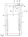
- Fig. 2 the self-locking 5 is shown schematically.
- the rope 40 has a downward rope length 42 and an essentially horizontal rope length 43, which in FIG. 3 is also inclined.
- the weight of the base plate with the gas bottle is directed onto the hand lever 7 via the cable 40.
- the fixed roller 11 is provided, which redirects the direction of action of the force.
- the force always runs parallel to the respective rope pieces, ie essentially horizontally between the roller 11 and the attachment point 75.
- the resulting weight force thus acts between the attachment point 75 and the contact point 13 of the rope 40 on the roller 11 and extends in the pulled-up, worn-out manner Position below the fulcrum 70 of the hand lever 7.
- This configuration advantageously produces a torque 77 which acts clockwise about the fulcrum 70 and which presses the hand lever 7 against the frame 1.
- a not shown stop on the frame 1 is provided.
- Fig. 3 the lowered position of the base plate 3 is shown.
- the base plate 3 can be loaded with the gas bottle.
- the frame 1 is designed so that it does not reach the floor, but maintains a certain distance from the floor. In this embodiment, the frame 1 does not affect the ground clearance of the movable welding apparatus, for example.
- the lower edge of the frame 1 includes z. B. with the lower edge of the housing of the welding apparatus.
- the upwardly pivoted hand lever 7 causes the base plate 3 to be lowered.
- the rope length 43 running between the attachment point 75 and the roller 11 is inclined upward from the horizontal by an angle of approximately 45 °.
- the rope length 43 is significantly shortened compared to the configuration in FIG. 2, as a result of which the lowering of the base plate 3 is achieved.
- a stop (not shown) is provided on the upper, horizontal spar 10, which prevents the hand lever 7 from tipping over.
- the device according to the invention can also be equipped with more than one deflection roller around which the rope for lifting the base plate is guided. It is also possible that the L-shaped base plate is dispensed with and an essentially flat base plate is used, to which the lifting means acts.
- the base plate in particular when the device is used tilted, simultaneously forms a guide or stop for the gas bottle.
- FIG. 4 shows a further embodiment of the invention.
- the device according to the invention is combined here with a bottle cart known per se.
- the special feature of this configuration is that a bottle can be easily transported in this combination and then raised to a corresponding level by the lifting device 104 in order to transfer it to a corresponding bottle receiving station.
- the frame 102 has wheels 110 which are rotatably mounted about an axis 111.
- the frame 101 or the bottle trolley 102 can also be pivoted about this axis 111, which at the same time acts here as a horizontal axis 112.
- the bottle trolley 102 has two struts 120 running essentially parallel and upwards.
- the struts 120 form the handles 121 in the upper region.
- the struts 120 are arranged in such a way that the gas bottle can be easily accommodated between them.
- the struts 120 are bent forward in the upper region of the bottle trolley 2 and then describe a U which adjoins in the direction of the handle 121.
- a funnel shape is achieved which optimally encloses and secures the gas bottles.
- loop chains (not shown) can be provided which reliably prevent the bottles from slipping out unintentionally.
- An actuating lever 122 is arranged on the handle 121. By means of this actuating lever 122, on the one hand a brake 103 and on the other hand the anti-lowering device 105 is released if necessary. The brake 103 and the anti-lowering device 105 are connected to the actuating lever 122 by a common Bowden cable 123. By actuating the actuating lever 122, both the brake 3 and the lowering safety device 5 are actuated simultaneously. In the unactuated state, the bottle trolley 102 is fixed by the brake 103. It is e.g. provided to arrange either only one brake, as shown in FIG. 5, or an acting brake 103 on each wheel. This configuration ensures that unintentional rolling away of the bottle trolley 2 is avoided.
- the Bowden cable 123 also acts on the lowering safeguard 105, which is released when the actuating lever 22 is pressed.
- the base plate 140 is lowered into the lowest position, which is advantageous for transporting the gas bottles.
- the gas bottle is placed on the bottle trolley 102 from the floor, this being achieved by simply tilting the gas bottle and simultaneously moving the base plate 40 under the gas bottle.
- the frame 101 is usually pivoted counterclockwise in the direction of the arrow 113 in order to transport the bottle.
- the base plate 140 has side cheeks in order to give the gas bottle a lateral hold in the lower region.
- the lifting device 104 includes in particular retaining lugs 141 at the front end of the base plate 140. It is provided that the base plate 140 e.g. L-shaped and has in the substantially vertical section guides 142, by means of which the base plate 140 on the frame 101 is substantially vertically displaceable.
- Fig. 4 the upper position of the base plate 140 is indicated by dashed lines. This position is achieved, for example, in that the holding lugs 141, when the bottle trolley 102 is pivoted for transport, engages in holding projections provided at the bottle receiving stations. At that moment the bottle has not yet been lifted. If the frame 1 is now pivoted clockwise around the horizontal axis 112, which corresponds here to the shaft 111 of the wheels 110, that is to say against the arrow 113, the base plate 140 moves upward in its guides 142, since the retaining lug 141 is held at a corresponding level with the holding projections of the bottle receiving station (not shown further).
- This configuration has the particular advantage that the platform 104 has no problems exactly the right level of the bottle receiving station is reached, without time-consuming adjustment or readjustment work. Reloading the gas bottle from the bottle truck 102 to the bottle receiving station (not shown) is possible without any problems. It is also possible to arrange the base plate 140 slightly above the level of the bottle receiving station in order to achieve an easy transfer due to the gradient.
- the operating lever 122 is advantageously not pressed and the parking brake 3 holds the bottle trolley 2 in one and the same position. It is also possible to lightly operate the manual operating lever 122 to enable the wheels 110 to be inevitably displaced during the raising process.
- the holding lug 141 is detached from the holding projection, which e.g. can be done by simply pivoting backwards 113. If the actuating lever 122 is now actuated, the lowering safeguard 105 is first released and the base plate 140 in the guide 142 is lowered.
- a lowering is first proposed and only then is the brake 103 released.
- the operation of the lowering safeguard 105 is indicated in FIG. 7.
- a rotatably mounted lever 150, on which the Bowden cable 123 is arranged, is arranged on the strut 114 of the frame 101 attacks.
- the Bowden cable 123 acts against the force of a spring 151, which causes the lever 150 to engage in a rack 152 at its front end.
- the rack 152 is connected to the base plate 140 and moves with it from the lowest to the highest position.
- the spring 151 causes the lever 50 to snap securely between the teeth 153 of the rack 152, as occurs, for example, when the lever device 104 is moved up.
- the lowering movement which takes place by releasing the lowering safeguard 105, can be braked, for example, by appropriate pneumatic shock absorbers or the like.
- the brake 103 is shown.
- a brake shoe 130 is pressed onto the wheel 110 by a spring 131.
- the Bowden cable 123 engages in an eyelet of the brake shoe 130 and, against the force of the spring 131, pulls the brake shoe 130 away from the wheel 110 and releases it.
Landscapes
- Engineering & Computer Science (AREA)
- General Engineering & Computer Science (AREA)
- Mechanical Engineering (AREA)
- Handcart (AREA)
- Drying Of Solid Materials (AREA)
Abstract
Description
Die Erfindung betrifft eine Vorrichtung für die Aufnahme einer Gasflasche, wobei an der Vorrichtung eine Standplatte für die Gasflasche vorgesehen ist.The invention relates to a device for holding a gas bottle, a stand plate for the gas bottle being provided on the device.
Die Verwendung von Gas im täglichen Leben ist weit verbreitet. Es ist bekannt, Gas z.B. in der Industrie, im Handel, im Handwerk, in Dienstleistungsbetrieben und im medizinischen Bereich, in Hallenbäder und vielen anderen Bereichen einzusetzen. Das Gas wird hierbei in Gasflaschen angeliefert. Das in den Gasflaschen vorhandene Gas erfüllt unterschiedlichste Aufgaben. Das Gas wird z.B. beim Schweißen verwendet. Das Gas ergibt hierbei z.B. eine abgeschlossene Atmosphäre, damit an dem Schweißpunkt eine optimale Schweißnaht entsteht. Sauerstoff, Stickstoff, Wasserstoff, Helium, Chlor, Kohlendioxid und viele weitere gasförmige Elemente bzw. Zusammensetzungen werden in Gasflaschen transportiert bzw. vorgehalten. Es ist z.B. bekannt, in Krankenhäuser spezielle Sauerstoffbehandlungen durchzuführen, bei denen der Sauerstoff in Sauerstoffgasflaschen vorgehalten wird. In Hallenbädern wird das Wasser durch Chlor aus Chlorgasflaschen desinfiziert. Die Verwendung all dieser Gasflaschen haben ein gemeinsames Problem.The use of gas in everyday life is widespread. It is known to use gas, for example in industry, in trade, in handicrafts, in service companies and in the medical field, in indoor swimming pools and many other areas. The gas is delivered in gas bottles. The gas in the gas bottles fulfills a wide variety of tasks. The gas is used, for example, for welding. The gas results in a closed atmosphere, for example, in the Weld spot creates an optimal weld. Oxygen, nitrogen, hydrogen, helium, chlorine, carbon dioxide and many other gaseous elements or compositions are transported or stored in gas bottles. For example, it is known to carry out special oxygen treatments in hospitals in which the oxygen is kept in oxygen gas bottles. In indoor pools, the water is disinfected by chlorine from chlorine gas bottles. The use of all of these gas cylinders has a common problem.
Diese Gasflaschen weisen ein hohes Gewicht, typischerweise 70 Kilogramm und mehr auf. Der Transport dieser Gasflaschen ist beschwerlich und unter Umständen auch gefährlich, weil die Gasflaschen sehr unhandlich und nicht mit Tragehilfen ausgestattet sind. Die bekannten Standplatten weisen vom Boden einen gewissen Abstand auf. Dieser Abstand ist notwendig, damit die Vorrichtung, die z.B. auf Rollen oder Räder verfahrbar ist, eine gewisse Bodenfreiheit behält, oder der Bereich unter der Gasflasche für das Reinigen des Bodens, z.B. in Reinräumen oder im klinischen Bereich, freizuhalten. Das Beladen der Vorrichtung mit den Gasflaschen ist mit einem Hochheben der Gasflasche verbunden, wobei dies zum einen gesundheitliche Risiken beinhalten kann, zum anderen, beispielsweise wenn die Gasflasche sehr schlüpfrig ist, fast unmöglich ist.These gas bottles are heavy, typically 70 kilograms or more. The transport of these gas bottles is difficult and under certain circumstances also dangerous because the gas bottles are very bulky and are not equipped with carrying aids. The known base plates have a certain distance from the floor. This distance is necessary so that the device, e.g. is movable on rollers or wheels, maintains a certain ground clearance, or the area under the gas bottle for cleaning the floor, e.g. in clean rooms or in clinical areas. Loading the device with the gas bottles involves lifting the gas bottle, which on the one hand can involve health risks and on the other hand is almost impossible, for example if the gas bottle is very slippery.
Die Erfindung hat es sich zur Aufgabe gemacht, Vorrichtungen wie eingangs beschrieben dahingehend zu verbessern, daß ein Beladen der Vorrichtung mit der Gasflasche problemlos möglich ist.The invention has set itself the task of improving devices as described in the introduction so that loading the device with the gas bottle is possible without any problems.
Zur Lösung dieser Aufgabe geht die Erfindung aus von einer Vorrichtung wie eingangs beschrieben und schlägt vor, daß die Standplatte höhenverstellbar ist und eine Hebevorrichtung für die Höhenverstellung vorgesehen ist.To achieve this object, the invention is based on a device as described in the introduction and suggests that the base plate is adjustable in height and a lifting device is provided for the height adjustment.
Durch die erfindungsgemäße Ausgestaltung ist es möglich, daß die Standplatte für das Beladen mit der Gasflasche bis auf den Boden absenkbar ist, die Gasflasche durch einfaches Verkippen unterfahren wird oder die Gasflasche auf die Standplatte aufgerollt wird. Für den Transport der Gasflasche kann nun die Standplatte der Gasflasche über die Hebevorrichtung angehoben werden, und die höhenverstellbare Standplatte wird soweit vom Boden angehoben, damit diese z.B. die gleiche Bodenfreiheit aufweist wie die mit Rollen versehene Vorrichtung. Durch die erfindungsgemäße Lösung wird auf das Hochheben der Gasflasche vollkommen verzichtet, eine Beeinträchtigung der Gesundheit der Bedienungsperson ist dadurch ausgeschaltet. Auch werden mögliche Unfallrisiken, die durch ein Entgleiten der Gasflasche entstehen können, vollkommen vermieden, da ein händisches Heben der Gasflasche nicht mehr notwendig ist.The configuration according to the invention makes it possible for the base plate to be lowered to the floor for loading with the gas bottle, for the gas bottle to be moved under by simply tilting, or for the gas bottle to be rolled up onto the base plate. For the transport of the gas bottle, the base plate of the gas bottle can now be lifted using the lifting device, and the height-adjustable base plate is raised so far from the floor that it e.g. has the same ground clearance as the wheeled device. The solution according to the invention means that there is no need to lift the gas bottle, which means that the operator's health is eliminated. Possible accident risks that can arise from the gas bottle slipping off are also completely avoided, since manual lifting of the gas bottle is no longer necessary.
In einer bevorzugten Ausgestaltung der Erfindung ist vorgesehen, daß als Hebevorrichtung ein drehbar gelagerter Handhebel vorgesehen ist, der über ein Hebeelement auf die Standplatte wirkt. Als Hebeelement ist hierbei zum Beispiel ein Seilzug, ein Gestänge, ein Getriebe oder eine Hydraulik vorgesehen. Der Handhebel wird durch eine Pumpbewegung oder eine Umlegebewegung betätigt und bewirkt durch das Hebeelement eine Höhenverstellung der Standplatte. Gleichwohl kann auch ein Kurbelantrieb mit einem Handhebel vorgesehen werden, wobei der Kurbelantrieb bzw. der Spindelantrieb über eine Haspel mit Seilzug oder über ein Schneckengetriebe als Hebevorrichtung auf die Höhenverstellung der Standplatte wirkt.In a preferred embodiment of the invention it is provided that a rotatably mounted hand lever is provided as the lifting device, which acts on the base plate via a lifting element. For example, a cable pull, a linkage, a gearbox or a hydraulic system is provided as the lifting element. The hand lever is actuated by a pumping movement or a folding movement and causes the height of the base plate to be adjusted by the lifting element. Nevertheless, a crank drive with a hand lever can also be provided, the crank drive or the spindle drive acting on the height adjustment of the base plate via a reel with a cable pull or via a worm gear as a lifting device.
In einer weiteren bevorzugten Ausgestaltung der Erfindung ist vorgesehen, daß eine elektrische Hebevorrichtung vorgesehen ist. Die Gasflaschen werden z.B. beim Schweißen verwendet. Die Schweißapparate werden in aller Regel mit dem Stromnetz verbunden. Oftmals bewirkt der Strom das eigentliche Schweißen, und das Gas bewirkt nur eine Schutzgasatmosphäre. An der Hebevorrichtung kann ein Elektromotor mit Getriebe vorgesehen werden, der an die Stromversorgung des Schweißapparates angeschlossen wird und mit einer einfachen Steuerung ein Anheben und Absenken der Standplatte und der darauf befindlichen Gasflasche bewirkt.In a further preferred embodiment of the invention it is provided that an electrical lifting device is provided. The gas bottles are used, for example, for welding. The welding equipment is usually connected to the power grid. Often the current does the actual welding, and the gas only creates a protective gas atmosphere. An electric motor with a gear can be provided on the lifting device, which is connected to the power supply of the welding apparatus and, with a simple control, causes the base plate and the gas bottle located thereon to be raised and lowered.
Die erfindungsgemäße Vorrichtung ist sowohl als Nachrüstaggregat ausgestaltet, d.h. die Vorrichtung ist dazu geeignet, an bestehende Schweißapparate angebaut zu werden, oder aber die Vorrichtung ist in neu zu fertigende Schweißapparate integriert. Die erfindungsgemäße Vorrichtung dient sowohl dazu, nur eine, wie auch mehrere Gasflaschen aufzunehmen.The device according to the invention is designed both as a retrofit unit, i.e. the device is suitable for being attached to existing welding devices, or the device is integrated in welding devices to be newly manufactured. The device according to the invention serves both to accommodate only one and also several gas bottles.
In einer weiteren bevorzugten Ausgestaltung der Erfindung ist vorgesehen, daß die Vorrichtung stationär insbesondere in einer Wand befestigbar ausgebildet ist.In a further preferred embodiment of the invention it is provided that the device is designed to be stationary, in particular fastened in a wall.
In einer weiteren Ausgestaltung der Erfindung ist vorgesehen, daß die Vorrichtung an einem fahrbaren Gestell vorgesehen ist. Die Einsetzmöglichkeiten der Vorrichtung sind keineswegs begrenzt. Überall da, wo Gasflaschen entweder transportiert oder gelagert werden, besteht das Problem, daß diese auf eine Standplatte aufgestellt werden müssen, wodurch die eingangs geschilderten Probleme entstehen. Die Vorrichtung gemäß der Ausgestaltung der Erfindung kann somit stationär, also im wesentlichen unbeweglich ausgebildet sein. Hierzu ist z.B. vorgesehen, daß die Vorrichtung an einer Wand oder im Boden verankerbar ausgebildet ist.In a further embodiment of the invention it is provided that the device is provided on a mobile frame. The possible uses of the device are by no means limited. Wherever gas cylinders are either transported or stored, there is the problem that they have to be placed on a base plate, as a result of which the problems described at the outset arise. The device according to the embodiment of the invention can thus be designed to be stationary, that is to say essentially immobile. For this, e.g. provided that the device is designed to be anchored on a wall or in the floor.
Aber auch für den Transport der Gasflaschen ist es von Vorteil, wenn die Transportvorrichtung eine erfindungsgemäße Ausgestaltung aufweist. Gerade der Transport der Gasflaschen ist unter Umständen sehr gefährlich, da das Be- und Entladen zwei Gefahrenquellen im Umgang mit den Gasflaschen birgt.But it is also advantageous for the transport of the gas bottles if the transport device has an embodiment according to the invention. Transporting the gas bottles in particular can be very dangerous, since loading and unloading harbors two sources of danger when handling the gas bottles.
Hervorzuheben ist hierbei, daß die erfindungsgemäße Vorrichtung bei der Verwendung an Schweißapparaten von Vorteil ist. Bei Schweißapparaten können eine oder mehrere Gasflaschen Verwendung finden. Der Gasverbrauch ist durchaus unterschiedlich und die Gasflaschen müssen gewechselt werden. Der Schweißapparat kann z.B. ein fahrbares Gestell oder Rollen oder dergleichen aufweisen. Der Schweißapparat kann aber auch stationär ausgebildet sein. Durch die erfindungsgemäße Ausgestaltung wird das Beladen bzw. Austauschen der Gasflaschen an dem Schweißapparat wesentlich erleichtert.It should be emphasized here that the device according to the invention is advantageous when used on welding apparatus. One or more gas cylinders can be used in welding equipment. The gas consumption is quite different and the gas bottles have to be changed. The welding apparatus can e.g. have a mobile frame or castors or the like. However, the welding apparatus can also be designed to be stationary. The configuration according to the invention makes it much easier to load or replace the gas bottles on the welding apparatus.
In der bevorzugten Ausgestaltung der Erfindung ist vorgesehen, daß als Hebevorrichtung das fahrbare Gestell dient, welches um eine horizontale Achse schwenkbar ist und die Standplatte mit einer Haltenase ausgestaltet ist, die bei Betätigung der Hebevorrichtung in einem Haltevorsprung einer Flaschenaufnahmestation eingreift und die Hebevorrichtung durch ein Zurückschwenken des Gestells die Gasflasche anhebt. Das fahrbare Gestell hat gemäß diesem Vorschlag nicht nur die Aufgabe, gleich einer Flaschenkarre, die Flaschen zu transportieren, sondern dient auch gleichzeitig als Hebevorrichtung, um ein Anheben der Gasflasche auf das entsprechende Abstellniveau der Gasflasche an einer Flaschenaufnahmestation zu bewirken. Eine Flaschenaufnahmestation ist hierbei z.B. die Standfläche der Gasflasche an einem Schweißapparat oder die Flaschenhalterung an einer Wand oder dergleichen. Dieser Flaschenkarren weist üblicherweise eine Achse mit zwei Rädern auf, wobei die Achse gleichzeitig als horizontale Achse dient, um welche das fahrbare Gestell verschwenkbar ist. Für den Transport ist es günstig, den Karren nach hinten zu schwenken und somit den Schwerpunkt des beladenen Karrens im wesentlichen über der Drehachse anzuordnen, wodurch ein leichter Transport der Gasflasche möglich ist. In dieser verschwenkten Stellung steht das vordere Ende der Standplatte mit einer oder mehreren Haltenasen vom Boden ab. Diese schräge Stellung wird dazu benützt, um die Haltenase in Eingriff mit an der Flaschenaufnahmestation vorgesehenen Haltevorsprüngen zu bringen. Durch eine entsprechende Anordnung der Standplatte bzw. dem Verschwenkwinkel können somit Höhenunterschiede von bis zu 30 cm überwunden werden. Wenn die Haltenase mit einem Haltevorsprung der Flaschenaufnahmestation verbunden ist, wird das fahrbare Gestell um die Horizontalachse zurückgeschwenkt, wodurch die Gasflasche wieder senkrecht gestellt wird. Gleichzeitig zieht sich die Standplatte an dem Haltevorsprung nach oben, wobei die Standplatte mit Längsführungen an dem fahrbaren Gestell befestigt ist.In the preferred embodiment of the invention it is provided that the mobile frame serves as the lifting device, which can be pivoted about a horizontal axis and the base plate is designed with a holding lug which engages in a holding projection of a bottle receiving station when the lifting device is actuated and the lifting device is pivoted back of the rack lifts the gas bottle. According to this proposal, the mobile frame not only has the task of transporting the bottles like a bottle cart, but also serves at the same time as a lifting device in order to raise the gas bottle to the corresponding storage level of the gas bottle at a bottle receiving station. A bottle receiving station is, for example, the base of the gas bottle on a welding machine or the bottle holder on a wall or the like. This bottle cart usually has an axle with two wheels, the axle simultaneously serving as a horizontal axis about which the mobile frame can be pivoted. For transportation, it is favorable to swivel the cart backwards and thus to arrange the center of gravity of the loaded cart essentially above the axis of rotation, whereby an easy transportation of the gas bottle is possible. In this pivoted position, the front end of the base plate protrudes from the floor with one or more retaining lugs. This inclined position is used to bring the retaining lug into engagement with retaining projections provided at the bottle receiving station. Appropriate arrangement of the base plate or the swivel angle means that height differences of up to 30 cm can be overcome. If the holding lug is connected to a holding projection of the bottle receiving station, the mobile frame is pivoted back about the horizontal axis, as a result of which the gas bottle is again placed vertically. At the same time, the base plate pulls upwards on the holding projection, the base plate being fastened to the mobile frame with longitudinal guides.
Es ist günstig, wenn die Hebevorrichtung eine Absenksicherung aufweist. Diese Absenksicherung ist lösbar ausgestaltet und verhindert ein unbeabsichtigtes Herabgleiten der Hebevorrichtung.It is advantageous if the lifting device has a lowering protection. This lowering lock is designed to be detachable and prevents the lifting device from sliding down unintentionally.
In der bevorzugten Ausgestaltung der Erfindung ist vorgesehen, daß eine Feststellbremse für die Räder des fahrbaren Gestells vorgesehen ist und vor dem Lösen der Feststellbremse die Standplatte durch das Lösen der Absenksicherung absinkt. Durch eine solche Ausgestaltung wird erreicht, daß vor einem Transport der Gasflasche, hierzu ist das Lösen der Bremsen notwendig, sichergestellt wird, daß zunächst die Standplatte abgesenkt wird, wodurch ein sicherer Transport der Flasche erfolgt.In the preferred embodiment of the invention it is provided that a parking brake is provided for the wheels of the mobile frame and the base plate sinks by releasing the lowering lock before releasing the parking brake. Such a configuration ensures that before the gas bottle is transported, for which purpose the brakes must be released, it is ensured that the base plate is first lowered, as a result of which the bottle is transported safely.
Durch eine vorteilhafte Ausgestaltung der Erfindung wird erreicht, daß die Feststellbremse und die Absenkvorrichtung durch einen gemeinsamen Bowdenzug nacheinander betätigbar sind. Der Bowdendruck ist verbunden mit einem Betätigungshebel. Im nicht betätigten Zustand drückt die Feststellbremse auf das Rad und verhindert ein Wegrollen des fahrbaren Gestells. Für ein Transportieren der Gasflasche auf dem fahrbaren Gestell ist somit ein Lösen der Feststellbremse notwendig, wobei wie beschrieben zuerst die Absenksicherung gelöst wird, wodurch die Gasflasche abgesenkt wird und dann die Feststellbremse lösbar ist. Die Verwendung eines Bowdenzuges mit variabler Länge in den Teilzügen für die Feststellbremse und die Absenksicherung stellt eine einfache aber sichere Lösung dar.An advantageous embodiment of the invention ensures that the parking brake and the lowering device can be actuated in succession by a common Bowden cable. The bowden pressure is connected to an operating lever. When not in use, the parking brake presses on the wheel and prevents the mobile frame from rolling away. For transporting the gas bottle on the mobile frame thus a release of the parking brake is necessary, the lowering lock being released first, as described, as a result of which the gas bottle is lowered and then the parking brake can be released. The use of a Bowden cable with variable length in the partial cables for the parking brake and lowering protection is a simple but safe solution.
Weitere erfindungsgemäße Ausgestaltungen sind in den Unteransprüchen beschrieben.Further configurations according to the invention are described in the subclaims.
In der Zeichnung ist die Erfindung schematisch dargestellt. Es zeigen:
- Fig.1
- eine dreidimensionale Ansicht der erfindungsgemäßen Vorrichtung in einer angehobenen Stellung,
- Fig. 2
- eine Frontansicht gemäß Fig. 1 und
- Fig. 3
- eine weitere dreidimensionale Ansicht der erfindungsgemäßen Vorrichtung in einer abgesenkten Stellung,
- Fig. 4
- in einer Seitenansicht eine weitere Ausgestaltung der erfindungsgemäßen Vorrichtung,
- Fig. 5
- in einer Rückansicht eine weitere Ausgestaltung der erfindungsgemäßen Vorrichtung,
- Fig. 6
- ein Detail gemäß Fig. 5 der erfindungsgemäßen Vorrichtung und
- Fig. 7
- ein weiteres Detail gemäß Fig. 5 der erfindungsgemäßen Vorrichtung.
- Fig. 1
- 3 shows a three-dimensional view of the device according to the invention in a raised position,
- Fig. 2
- a front view of FIG. 1 and
- Fig. 3
- another three-dimensional view of the device according to the invention in a lowered position,
- Fig. 4
- a side view of a further embodiment of the device according to the invention,
- Fig. 5
- in a rear view a further embodiment of the device according to the invention,
- Fig. 6
- a detail of FIG. 5 of the device according to the invention and
- Fig. 7
- a further detail according to FIG. 5 of the device according to the invention.
In Fig. 1 ist die erfindungsgemäße Vorrichtung gezeigt. Für eine bessere Übersichtlichkeit ist auf die Darstellung eines Schweißapparates, an dem die Vorrichtung z.B. vorgesehen ist, verzichtet worden. Genauso ist in der hier dargestellten hochgezogenen Stellung die Gasflasche nicht gezeigt.1 shows the device according to the invention. For a better clarity, the representation of a welding apparatus on which the device e.g. is provided has been waived. Likewise, the gas bottle is not shown in the raised position shown here.
Die Vorrichtung besteht im wesentlichen aus einem Rahmen 1, der zum Beispiel rechteckig ausgebildet ist und an seinen im wesentlichen senkrecht verlaufenden Holmen 14 Führungen 2 aufweist. Der Rahmen 1 ist beispielsweise aus verschweißten Holmen hergestellt, die Führungen 2 sind auf diesen Holmen aufgeschweißt.The device consists essentially of a
Die Gasflasche steht auf der Standplatte 3. Die Standplatte 3 ist hierbei L-artig 30 ausgebildet, wobei die Gasflasche auf der im wesentlichen waagrecht ausgerichteten Standfläche 31 steht. Die Standfläche 31 bildet hierbei den kürzeren Schenkel der L-artig 30 ausgebildeten Standplatte 3. Das im wesentlichen senkrecht angeordnete Element 32 der Standplatte 3 ist in der Führung 2 derart geführt, daß die L-artige 30 Standplatte 3 eine Höhenverstellung entlang des Doppelpfeiles 6 ausführen kann.The gas bottle stands on the
In einer weiteren Ausgestaltung ist vorgesehen, daß die Standplatte 3 im wesentlichen eben ist und entsprechende Hebeelemente an der Standplatte 3 angreifen.In a further embodiment it is provided that the
Für eine sichere Führung für die auf die Standfläche 31 gestellte Gasflasche weist die Standfläche 31 seitliche hochgebogene Ränder 33 auf. Für eine weitere Sicherung der Flasche sind entsprechende Mittel, z.B. Sicherungsketten usw. vorgesehen.For secure guidance of the gas bottle placed on the standing
Für das Anheben bzw. Absenken der Standplatte 3 ist eine Hebevorrichtung 4 vorgesehen. Diese Hebevorrichtung 4 ist in der in Fig. 1 gezeigten Ausführung als Seilzug 40 ausgebildet, der am oberen Ende des senkrechten Elementes 32 am Angriffspunkt 41 angreift. Um ein Verkippen oder Verkanten der Standplatte 3 in der Führung 2 zu vermeiden, ist vorgesehen, daß der Angriffspunkt 41 möglichst in der Mitte der senkrechten Platte 32 am oberen Rand angeordnet ist.A
Der Seilzug 40 greift an dem Angriffspunkt 41 an und wird über eine feststehende, sich drehende Rolle im wesentlichen rechtwinklig abgelenkt. Die Rolle 11 ist an dem oberen waagrechten Holm 10 derart vorgesehen, daß der Seilzug 40 im wesentlichen senkrecht verläuft.The
Wenn man vor dem Rahmen 1 steht, ist auf der rechten Seite der Handhebel 7 vorgesehen. Der Handhebel 7 ist ebenfalls am oberen waagrechten Holm 10 in einem Drehpunkt 70 drehbar gelagert. Der Handhebel 7 ist L-artig 71 ausgebildet, wobei der kürzere Schenkel 72 deutlich kürzer ist als der lange Schenkel 73, an dem auch der Handgriff 74 vorgesehen ist.If you stand in front of the
An dem kurzen Schenkel 72 ist das umgelenkte Seil 40 im Anschlagpunkt 75 angeschlagen. Das Absenken der Standplatte 3 erfolgt durch ein Verschwenken des Handhebels 7 entsprechend der Verschwenkbewegung 76 entgegen dem Uhrzeigersinn. Durch diese Verschwenkbewegung 76 wird die Entfernung des Anschlagpunktes 75 von dem Drehpunkt 12 der Rolle 11 verkürzt und dadurch die nach unten wirksame Seillänge 42 verlängert. Hieraus resultiert ein Absenken der Standplatte 3.The deflected
Für den Handhebel 7 ist günstigerweise eine Selbstarretierung 5 vorgesehen. Durch die Selbstarretierung 5 wird bewirkt, daß der Handhebel 7 in einer selbst fixierten Lage stabil gehalten ist. Dadurch wird ein unbeabsichtigtes Absenken der Standplatte sicher vermieden, da für ein Absenken der Standplatte 3 zunächst der Handhebel 7 über die Selbstarretierung 5 bewegt werden muß, um eine Absenkung zu erreichen.A self-locking device 5 is advantageously provided for the
In Fig. 2 ist die Selbstarretierung 5 schematisch gezeigt. Das Seil 40 weist eine nach unten gerichtete Seillänge 42 und eine im wesentlichen waagrecht, in Fig. 3 auch schräg verlaufende Seillänge 43 auf. Das Gewicht der Standplatte mit der Gasflasche wird über den Seilzug 40 auf den Handhebel 7 gelenkt.In Fig. 2 the self-locking 5 is shown schematically. The
Hierzu ist die feststehende Rolle 11 vorgesehen, die die Wirkungsrichtung der Kraft umlenkt. Die Kraft verläuft immer parallel zu den jeweiligen Seilstücken, also im wesentlichen waagrecht zwischen der Rolle 11 und dem Anschlangpunkt 75. Die resultierende Gewichtskraft wirkt also zwischen dem Anschlagpunkt 75 und dem Anlagepunkt 13 des Seiles 40 an der Rolle 11 und verläuft in der hochgezogenen, abgefahrenen Stellung unterhalb des Drehpunktes 70 des Handhebels 7. Durch diese Ausgestaltung wird günstigerweise ein um den Drehpunkt 70 im Uhrzeigersinn wirkendes Drehmoment 77 erzeugt, das den Handhebel 7 gegen den Rahmen 1 drückt. Für eine Begrenzung der Bewegung des Handhebels 7 ist z.B. ein nicht weiter dargestellter Anschlag an dem Rahmen 1 vorgesehen.For this purpose, the fixed
Hierbei ist es günstig, daß für den Handhebel 7 eine Verschwenkbewegung 76 um den Drehpunkt 70 von 180° möglich ist.It is advantageous here that a
In Fig. 3 ist die abgesenkte Stellung der Standplatte 3 gezeigt. In dieser Stellung kann die Standplatte 3 mit der Gasflasche beladen werden. Der Rahmen 1 ist hierbei so ausgebildet, daß dieser nicht bis an den Boden reicht, sondern von dem Boden einen gewissen Abstand einhält. Bei dieser Ausgestaltung beeinträchtigt der Rahmen 1 nicht die Bodenfreiheit des z.B. verfahrbaren Schweißapparates. Die Unterkante des Rahmens 1 schließt z. B. mit der Gehäuseunterkante des Schweißapparates ab. Wie oben beschrieben, bewirkt der nach oben geschwenkte Handhebel 7 ein Absenken der Standplatte 3. Die zwischen dem Anschlagpunkt 75 und der Rolle 11 verlaufende Seillänge 43 ist hierbei aus der Waagrechten nach oben um einen Winkel von ca. 45° geneigt. Die Seillänge 43 ist gegenüber der Ausgestaltung in Fig. 2 deutlich verkürzt, wodurch die Absenkung der Standplatte 3 erreicht wird. Für den Handhebel 7 ist an dem oberen, waagrechten Holm 10 ein nicht dargestellter Anschlag vorgesehen, der ein Umkippen des Handhebels 7 verhindert.In Fig. 3 the lowered position of the
Die erfindungsgemäße Vorrichtung kann auch mit mehr als einer Umlenkrolle ausgestattet sein, um die das Seil zum Anheben der Standplatte geführt ist. Es ist auch möglich, daß auf die L-artig ausgebildete Standplatte verzichtet wird und eine im wesentlichen ebene Standplatte verwendet wird, an die das Hebemittel angreift.The device according to the invention can also be equipped with more than one deflection roller around which the rope for lifting the base plate is guided. It is also possible that the L-shaped base plate is dispensed with and an essentially flat base plate is used, to which the lifting means acts.
Bei der L-artigen Ausgestaltung der Standplatte ist es von Vorteil, daß die Standplatte, insbesondere wenn die Vorrichtung gekippt verwendet wird, gleichzeitig eine Führung bzw. Anschlag für die Gasflasche bildet.In the L-like configuration of the base plate, it is advantageous that the base plate, in particular when the device is used tilted, simultaneously forms a guide or stop for the gas bottle.
In Fig. 4 ist eine weitere Ausgestaltung der Erfindung gezeigt. Die erfindungsgemäße Vorrichtung ist hier kombiniert mit einem an sich bekannten Flaschenkarren. Das besondere bei dieser Ausgestaltung liegt nun darin, daß in dieser Kombination problemlos eine Flasche transportiert werden kann und dann durch die Hebevorrichtung 104 auf ein entsprechendes Niveau angehoben wird, um diese in eine entsprechende Flaschenaufnahmestation zu übergeben.4 shows a further embodiment of the invention. The device according to the invention is combined here with a bottle cart known per se. The special feature of this configuration is that a bottle can be easily transported in this combination and then raised to a corresponding level by the
Das Gestell 102 weist Räder 110 auf, die um eine Achse 111 drehbar gelagert sind. Umgekehrt ist auch das Gestell 101 bzw. der Flaschenwagen 102 um diese Achse 111, die hier gleichzeitig als horizontale Achse 112 wirkt, verschwenkbar.The
Der Flaschenwagen 102 weist zwei im wesentlichen parallel, nach oben verlaufende Streben 120 auf. Die Streben 120 bilden im oberen Bereich die Handgriffe 121. Die Streben 120 sind hierbei so angeordnet, daß zwischen ihnen die Gasflasche problemlos Platz findet. Hierzu sind die Streben 120 im oberen Bereich des Flaschenwagens 2 nach vorne gebogen und beschreiben dann ein U, das sich in Richtung auf den Handgriff 121 anschließt. Durch eine winklige Anstellung der Streben 120 wird eine Trichterform erreicht, die die Gasflaschen optimal umfassen und sichern. Zusätzlich können nicht weiter dargestellte Schlingketten vorgesehen sein, die ein unbeabsichtigtes Herausgleiten der Flaschen sicher vermeiden.The
An dem Handgriff 121 ist ein Betätigungshebel 122 angeordnet. Durch diesen Betätigungshebel 122 wird zum einen eine Bremse 103 und zum anderen die Absenksicherung 105 bei Bedarf gelöst. Die Bremse 103 und die Absenksicherung 105 sind hierbei durch einen gemeinsamen Bowdenzug 123 mit dem Betätigungshebel 122 verbunden. Durch eine Betätigung des Betätigungshebels 122 werden also gleichzeitig sowohl die Bremse 3 wie auch die Absenksicherung 5 betätigt. Im unbetätigten Zustand wird der Flaschenwagen 102 durch die Bremse 103 fixiert. Es ist z.B. vorgesehen, entweder nur eine Bremse, wie in Figur 5 gezeigt, oder auf jedes Rad eine wirkende Bremse 103 anzuordnen. Durch diese Ausgestaltung wird erreicht, daß ein unbeabsichtigtes Wegrollen des Flaschenwagens 2 vermieden wird.An
Der Bowdenzug 123 wirkt auch auf die Absenksicherung 105, wobei diese gelöst wird, wenn der Betätigungshebel 22 gedrückt wird. Dadurch erfolgt eine Absenkung der Standplatte 140 in die niedrigste Position, wie diese zum Transportieren der Gasflaschen von Vorteil ist. Günstigerweise wird in der niedrigsten Position der Standplatte 140 die Gasflasche vom Boden auf den Flaschenwagen 102 gestellt, wobei dies durch ein einfaches Verkippen der Gasflasche und durch gleichzeitiges Unterfahren der Gasflasche mit der Standplatte 40 erreicht wird. Üblicherweise wird das Gestell 101 entgegen dem Uhrzeigersinn in Richtung des Pfeils 113 nach hinten geschwenkt, um die Flasche zu transportieren.The
Die Standplatte 140 weist seitliche Wangen auf, um der Gasflasche im unteren Bereich einen seitlichen Halt zu geben.The
Zur Hebevorrichtung 104 gehören insbesondere Haltenasen 141 am vorderen Ende der Standplatte 140. Es ist vorgesehen, daß die Standplatte 140 z.B. L-winklig ausgebildet ist und in dem im wesentlichen vertikal verlaufenden Abschnitt Führungen 142 aufweist, mit deren Hilfe die Standplatte 140 an dem Gestell 101 im wesentlichen vertikal verschiebbar ist.The
In Fig. 4 ist die obere Position der Standplatte 140 gestrichelt gekennzeichnet. Diese Position wird z.B. dadurch erreicht, daß die Haltenasen 141, wenn der Flaschenwagen 102 zum Transport entsprechend verschwenkt ist, in an Flaschenaufnahmestationen vorgesehenen Haltevorsprüngen eingreift. In diesem Moment ist die Flasche noch nicht angehoben worden. Wird nun das Gestell 1 um die horizontale Achse 112, die hier der Welle 111 der Räder 110 entspricht, im Uhrzeigersinn, also gegen den Pfeil 113 nach vorne, geschwenkt, so bewegt sich die Standplatte 140 in ihren Führungen 142 nach oben, da die Haltenase 141 mit den nicht weiter gezeigten Haltevorsprüngen der Flaschenaufnahmestation auf einem entsprechenden Niveau gehalten wird. Diese Ausgestaltung hat insbesondere den Vorteil, daß die Plattform 104 problemlos genau das richtige Niveau der Flaschenaufnahmestation erreicht, ohne aufwendige Justier- oder Nachregelarbeiten. Ein Umladen der Gasflasche von dem Flaschenwagen 102 auf die nicht weiter dargestellte Flaschenaufnahmestation ist problemlos möglich. Es ist auch möglich, die Standplatte 140 etwas überhalb dem Niveau der Flaschenaufnahmestation anzuordnen, um dadurch ein leichtes Umsetzen aufgrund des Gefälles zu erreichen.In Fig. 4 the upper position of the
Während des Umsetzens der Flasche von dem Gestell auf die Aufnahmestation oder umgekehrt ist günstigerweise der Bedienungshebel 122 nicht gedrückt und die Feststellbremse 3 hält den Flaschenwagen 2 in ein und derselben Position. Es ist auch möglich, den Handbetätigungshebel 122 leicht zu betätigen, um ein unvermeidliches Versetzen der Räder 110 während des Aufrichtvorganges zu ermöglichen.During the transfer of the bottle from the rack to the receiving station or vice versa, the operating
Nachdem die Gasflasche umgesetzt ist, sei es, daß die Gasflasche auf die Aufnahmestation aufgesetzt oder von dieser eine leere Gasflasche auf den Flaschenwagen 102 gesetzt wird, wird die Haltenase 141 von dem Haltevorsprung abgelöst, das z.B. durch ein einfaches Nach-hinten-Schwenken 113 erfolgen kann. Wird nun der Betätigungshebel 122 betätigt, wird zunächst die Absenksicherung 105 gelöst und es erfolgt ein Absenken der Standplatte 140 in der Führung 142.After the gas bottle has been transferred, be it that the gas bottle is placed on the receiving station or an empty gas bottle is placed on the
Erfindungsgemäß wird zunächst eine Absenkung vorgeschlagen und erst dann eine Freigabe der Bremse 103. Dies kann z.B. durch entsprechende unterschiedlich lange Teilstücke des Bowdenseilzuges erreicht werden, wobei die Bremse 103 erst bei einem größeren Betätigungsweg des Betätigungshebels 122 gelöst wird.According to the invention, a lowering is first proposed and only then is the
In Fig. 7 ist die Funktionsweise der Absenksicherung 105 angedeutet. An der Strebe 114 des Gestells 101 ist ein drehbar gelagerter Hebel 150 angeordnet, an dem der Bowdenzug 123 angreift. Der Bowdenzug 123 wirkt hierbei gegen die Kraft einer Feder 151, die bewirkt, daß der Hebel 150 an seinem vorderen Ende in einer Zahnstange 152 eingreift. Die Zahnstange 152 ist mit der Standplatte 140 verbunden und bewegt sich mit dieser von der niedrigsten in die höchste Position. Die Feder 151 bewirkt ein sicheres Einschnappen des Hebels 50 zwischen den Zähnen 153 der Zahnstange 152, wie dies z.B. bei einer Hochfahrbewegung der Hebelvorrichtung 104 erfolgt. Die Absenkbewegung, die durch ein Lösen der Absenksicherung 105 erfolgt, kann z.B. durch entsprechende pneumatische Stoßdämpfer oder dergleichen gebremst werden.The operation of the lowering
In Fig. 6 ist die Bremse 103 dargestellt. Ein Bremsbacken 130 wird durch eine Feder 131 auf das Rad 110 gedrückt. Der Bowdenzug 123 greift in einer Öse des Bremsbackens 130 an und zieht gegen die Kraft der Feder 131 den Bremsbacken 130 von dem Rad 110 weg und gibt dieses frei.6, the
Neben der Verwendung der hier vorgestellten zweiten Ausgestaltung an der Hebevorrichtung 104 in Verbindung mit einem Flaschenwagen 102 ist es auch möglich, die eingangs beschriebene Hebevorrichtung mit dem Handhebel an einem Flaschenwagen 102 anzuordnen.In addition to using the second embodiment presented here on the
Die jetzt mit der Anmeldung und später eingereichten Ansprüche sind Versuche zur Formulierung ohne Präjudiz für die Erzielung weitergehenden Schutzes.The claims now filed with the application and later are attempts to formulate without prejudice to achieve further protection.
Die in den abhängigen Ansprüchen angeführten Rückbeziehungen weisen auf die weitere Ausbildung des Gegenstandes des Hauptanspruches durch die Merkmale des jeweiligen Unteranspruches hin. Jedoch sind diese nicht als ein Verzicht auf die Erzielung eines selbständigen, gegenständlichen Schutzes für die Merkmale der rückbezogenen Unteransprüche zu verstehen.The back-references given in the dependent claims indicate the further development of the subject matter of the main claim through the features of the respective sub-claim. However, these are not to be understood as a waiver of the achievement of an independent, objective protection for the features of the related subclaims.
Merkmale, die bislang nur in der Beschreibung offenbart wurden, können im Laufe des Verfahrens als von erfindungswesentlicher Bedeutung, zum Beispiel zur Abgrenzung vom Stand der Technik beansprucht werden.Features that were previously only disclosed in the description can be claimed in the course of the method as being of importance for the invention, for example to distinguish them from the prior art.
Claims (16)
Applications Claiming Priority (6)
| Application Number | Priority Date | Filing Date | Title |
|---|---|---|---|
| DE29607409U | 1996-04-24 | ||
| DE29607409 | 1996-04-24 | ||
| DE29609228U DE29609228U1 (en) | 1996-04-24 | 1996-05-24 | Device for holding a gas bottle |
| DE29609228U | 1996-05-24 | ||
| DE29618981U DE29618981U1 (en) | 1996-04-24 | 1996-11-04 | Device for holding a gas bottle |
| DE29618981U | 1996-11-04 |
Publications (2)
| Publication Number | Publication Date |
|---|---|
| EP0803678A2 true EP0803678A2 (en) | 1997-10-29 |
| EP0803678A3 EP0803678A3 (en) | 1999-04-07 |
Family
ID=27219791
Family Applications (1)
| Application Number | Title | Priority Date | Filing Date |
|---|---|---|---|
| EP97106724A Withdrawn EP0803678A3 (en) | 1996-04-24 | 1997-04-23 | Device for supporting a gas bottle |
Country Status (1)
| Country | Link |
|---|---|
| EP (1) | EP0803678A3 (en) |
Cited By (3)
| Publication number | Priority date | Publication date | Assignee | Title |
|---|---|---|---|---|
| DE19933801C2 (en) * | 1999-07-19 | 2001-01-25 | Gerhard Stoermer | Transport cart for steel bottles |
| CN108523477A (en) * | 2018-06-19 | 2018-09-14 | 中绿能汉郁(天津)科技有限公司 | A kind of gas cabinet of quick fixed gas cylinder |
| CN114954590A (en) * | 2022-07-12 | 2022-08-30 | 淄博安泽特种气体有限公司 | A gas cylinder can be up and down telescopic transfer vehicle |
Family Cites Families (7)
| Publication number | Priority date | Publication date | Assignee | Title |
|---|---|---|---|---|
| DE1133100B (en) * | 1959-09-03 | 1962-07-12 | Maurice Darimont | Mobile lifting device for loads |
| US3870177A (en) * | 1973-06-25 | 1975-03-11 | Willard J Cobb | Mobile hand truck having a detachable load craddle |
| US4536123A (en) * | 1983-08-04 | 1985-08-20 | Snyder Wayne E | Hand truck apparatus for elevating and transporting an object |
| CH664120A5 (en) * | 1984-10-22 | 1988-02-15 | Sauerstoffwerk Lenzburg Ag | Device to create and move a steel bottle. |
| GB2202508B (en) * | 1987-03-24 | 1990-02-21 | Keith Nunnerley Aitchison | Multi-mode lifting/hauling/transporting apparatus |
| US5440098A (en) * | 1993-12-23 | 1995-08-08 | Miller Electric Manufacturing Co. | Gas cylinder lifting system |
| DE9405184U1 (en) * | 1994-03-26 | 1994-05-19 | Abel, Dietmar, 74542 Braunsbach | Bottle trolley for the transport of steel bottles |
-
1997
- 1997-04-23 EP EP97106724A patent/EP0803678A3/en not_active Withdrawn
Non-Patent Citations (1)
| Title |
|---|
| None |
Cited By (3)
| Publication number | Priority date | Publication date | Assignee | Title |
|---|---|---|---|---|
| DE19933801C2 (en) * | 1999-07-19 | 2001-01-25 | Gerhard Stoermer | Transport cart for steel bottles |
| CN108523477A (en) * | 2018-06-19 | 2018-09-14 | 中绿能汉郁(天津)科技有限公司 | A kind of gas cabinet of quick fixed gas cylinder |
| CN114954590A (en) * | 2022-07-12 | 2022-08-30 | 淄博安泽特种气体有限公司 | A gas cylinder can be up and down telescopic transfer vehicle |
Also Published As
| Publication number | Publication date |
|---|---|
| EP0803678A3 (en) | 1999-04-07 |
Similar Documents
| Publication | Publication Date | Title |
|---|---|---|
| DE2423954C3 (en) | Two-wheeled handcart | |
| DE69006119T2 (en) | Trolley for the transport of a cylindrical object. | |
| CH430106A (en) | Mobile lifting platform | |
| EP0152764B1 (en) | Loading process for an industrial truck and supporting carriage there for | |
| EP0570397A1 (en) | Workpiece-transport trolley | |
| EP3998170A1 (en) | Route train trailer | |
| DE3642700C2 (en) | ||
| DE19911872A1 (en) | Timber transporter consists of lorry with a bed (11) with timber -retaining frame whose vertical components can slide towards or away from each other, rear component also being mounted so its height above ground can be adjusted | |
| DE3602105A1 (en) | Lifting and transporting device for patients | |
| DE29618981U1 (en) | Device for holding a gas bottle | |
| EP0803678A2 (en) | Device for supporting a gas bottle | |
| DE3111750A1 (en) | Patient lifting device | |
| DE9412429U1 (en) | Suitable trolleys for moving on moving walks and escalators | |
| DE102019118305A1 (en) | Handcart for freight lifts | |
| DE102006014338B4 (en) | Tractor for transporting mobile transport containers | |
| DE4307918A1 (en) | Barrow | |
| DE4238187A1 (en) | Lifting and movement trolley partic. for pallets - has height adjustable roller between frame rollers on to which trolley frame may rest depending on height of adjustable roller | |
| AT396585B (en) | Equipment for operating storage racks | |
| DE3835500A1 (en) | Stacker truck | |
| DE60215797T2 (en) | TRANSPORT FOR TRANSPORTING A PRODUCT VIA A STAIRCASE | |
| EP0593954B1 (en) | Working tool to transport, rise and lower a dangerous load and hand truck designe for this use | |
| DE4424118C1 (en) | Bed, esp. hospital or treatment bed | |
| DE202012104333U1 (en) | transport equipment | |
| DE29609228U1 (en) | Device for holding a gas bottle | |
| DE4134948C2 (en) | Transport trolleys, in particular for empty warp beams |
Legal Events
| Date | Code | Title | Description |
|---|---|---|---|
| PUAI | Public reference made under article 153(3) epc to a published international application that has entered the european phase |
Free format text: ORIGINAL CODE: 0009012 |
|
| AK | Designated contracting states |
Kind code of ref document: A2 Designated state(s): AT BE CH DE DK FR GB IT LI NL SE |
|
| PUAL | Search report despatched |
Free format text: ORIGINAL CODE: 0009013 |
|
| AK | Designated contracting states |
Kind code of ref document: A3 Designated state(s): AT BE CH DE DK FR GB IT LI NL SE |
|
| STAA | Information on the status of an ep patent application or granted ep patent |
Free format text: STATUS: THE APPLICATION IS DEEMED TO BE WITHDRAWN |
|
| 18D | Application deemed to be withdrawn |
Effective date: 19991103 |