EP0803654B1 - Mehrfachventil und Filter/Abdichtung dafür - Google Patents
Mehrfachventil und Filter/Abdichtung dafür Download PDFInfo
- Publication number
- EP0803654B1 EP0803654B1 EP97106137A EP97106137A EP0803654B1 EP 0803654 B1 EP0803654 B1 EP 0803654B1 EP 97106137 A EP97106137 A EP 97106137A EP 97106137 A EP97106137 A EP 97106137A EP 0803654 B1 EP0803654 B1 EP 0803654B1
- Authority
- EP
- European Patent Office
- Prior art keywords
- bead
- manifold
- grid
- assembly defined
- filter
- Prior art date
- Legal status (The legal status is an assumption and is not a legal conclusion. Google has not performed a legal analysis and makes no representation as to the accuracy of the status listed.)
- Expired - Lifetime
Links
- 239000011324 bead Substances 0.000 claims description 22
- 239000000463 material Substances 0.000 claims description 8
- 239000013536 elastomeric material Substances 0.000 claims description 7
- 229920001971 elastomer Polymers 0.000 claims description 2
- 239000000806 elastomer Substances 0.000 claims description 2
- NBVXSUQYWXRMNV-UHFFFAOYSA-N fluoromethane Chemical compound FC NBVXSUQYWXRMNV-UHFFFAOYSA-N 0.000 claims description 2
- 229920000728 polyester Polymers 0.000 claims description 2
- 229910001220 stainless steel Inorganic materials 0.000 claims description 2
- 239000010935 stainless steel Substances 0.000 claims description 2
- 229920002379 silicone rubber Polymers 0.000 claims 1
- 230000005540 biological transmission Effects 0.000 description 13
- 239000012530 fluid Substances 0.000 description 10
- 238000007789 sealing Methods 0.000 description 7
- 238000001914 filtration Methods 0.000 description 6
- 230000005465 channeling Effects 0.000 description 1
- 238000000748 compression moulding Methods 0.000 description 1
- 238000011109 contamination Methods 0.000 description 1
- 238000001746 injection moulding Methods 0.000 description 1
- 230000004048 modification Effects 0.000 description 1
- 238000012986 modification Methods 0.000 description 1
- 239000002245 particle Substances 0.000 description 1
- 238000007493 shaping process Methods 0.000 description 1
- 229910052710 silicon Inorganic materials 0.000 description 1
- 239000010703 silicon Substances 0.000 description 1
- 125000006850 spacer group Chemical group 0.000 description 1
Images


Classifications
-
- F—MECHANICAL ENGINEERING; LIGHTING; HEATING; WEAPONS; BLASTING
- F15—FLUID-PRESSURE ACTUATORS; HYDRAULICS OR PNEUMATICS IN GENERAL
- F15B—SYSTEMS ACTING BY MEANS OF FLUIDS IN GENERAL; FLUID-PRESSURE ACTUATORS, e.g. SERVOMOTORS; DETAILS OF FLUID-PRESSURE SYSTEMS, NOT OTHERWISE PROVIDED FOR
- F15B13/00—Details of servomotor systems ; Valves for servomotor systems
- F15B13/02—Fluid distribution or supply devices characterised by their adaptation to the control of servomotors
- F15B13/06—Fluid distribution or supply devices characterised by their adaptation to the control of servomotors for use with two or more servomotors
- F15B13/08—Assemblies of units, each for the control of a single servomotor only
- F15B13/0803—Modular units
- F15B13/0807—Manifolds
- F15B13/081—Laminated constructions
-
- B—PERFORMING OPERATIONS; TRANSPORTING
- B01—PHYSICAL OR CHEMICAL PROCESSES OR APPARATUS IN GENERAL
- B01D—SEPARATION
- B01D29/00—Filters with filtering elements stationary during filtration, e.g. pressure or suction filters, not covered by groups B01D24/00 - B01D27/00; Filtering elements therefor
- B01D29/01—Filters with filtering elements stationary during filtration, e.g. pressure or suction filters, not covered by groups B01D24/00 - B01D27/00; Filtering elements therefor with flat filtering elements
- B01D29/05—Filters with filtering elements stationary during filtration, e.g. pressure or suction filters, not covered by groups B01D24/00 - B01D27/00; Filtering elements therefor with flat filtering elements supported
-
- F—MECHANICAL ENGINEERING; LIGHTING; HEATING; WEAPONS; BLASTING
- F15—FLUID-PRESSURE ACTUATORS; HYDRAULICS OR PNEUMATICS IN GENERAL
- F15B—SYSTEMS ACTING BY MEANS OF FLUIDS IN GENERAL; FLUID-PRESSURE ACTUATORS, e.g. SERVOMOTORS; DETAILS OF FLUID-PRESSURE SYSTEMS, NOT OTHERWISE PROVIDED FOR
- F15B13/00—Details of servomotor systems ; Valves for servomotor systems
- F15B13/02—Fluid distribution or supply devices characterised by their adaptation to the control of servomotors
- F15B13/06—Fluid distribution or supply devices characterised by their adaptation to the control of servomotors for use with two or more servomotors
- F15B13/08—Assemblies of units, each for the control of a single servomotor only
- F15B13/0803—Modular units
- F15B13/0832—Modular valves
- F15B13/0842—Monoblock type valves, e.g. with multiple valve spools in a common housing
-
- F—MECHANICAL ENGINEERING; LIGHTING; HEATING; WEAPONS; BLASTING
- F15—FLUID-PRESSURE ACTUATORS; HYDRAULICS OR PNEUMATICS IN GENERAL
- F15B—SYSTEMS ACTING BY MEANS OF FLUIDS IN GENERAL; FLUID-PRESSURE ACTUATORS, e.g. SERVOMOTORS; DETAILS OF FLUID-PRESSURE SYSTEMS, NOT OTHERWISE PROVIDED FOR
- F15B13/00—Details of servomotor systems ; Valves for servomotor systems
- F15B13/02—Fluid distribution or supply devices characterised by their adaptation to the control of servomotors
- F15B13/06—Fluid distribution or supply devices characterised by their adaptation to the control of servomotors for use with two or more servomotors
- F15B13/08—Assemblies of units, each for the control of a single servomotor only
- F15B13/0803—Modular units
- F15B13/0878—Assembly of modular units
- F15B13/0885—Assembly of modular units using valves combined with other components
- F15B13/0892—Valves combined with fluid components
-
- F—MECHANICAL ENGINEERING; LIGHTING; HEATING; WEAPONS; BLASTING
- F15—FLUID-PRESSURE ACTUATORS; HYDRAULICS OR PNEUMATICS IN GENERAL
- F15B—SYSTEMS ACTING BY MEANS OF FLUIDS IN GENERAL; FLUID-PRESSURE ACTUATORS, e.g. SERVOMOTORS; DETAILS OF FLUID-PRESSURE SYSTEMS, NOT OTHERWISE PROVIDED FOR
- F15B13/00—Details of servomotor systems ; Valves for servomotor systems
- F15B13/02—Fluid distribution or supply devices characterised by their adaptation to the control of servomotors
- F15B13/06—Fluid distribution or supply devices characterised by their adaptation to the control of servomotors for use with two or more servomotors
- F15B13/08—Assemblies of units, each for the control of a single servomotor only
- F15B13/0803—Modular units
- F15B13/0878—Assembly of modular units
- F15B13/0896—Assembly of modular units using different types or sizes of valves
-
- B—PERFORMING OPERATIONS; TRANSPORTING
- B01—PHYSICAL OR CHEMICAL PROCESSES OR APPARATUS IN GENERAL
- B01D—SEPARATION
- B01D2201/00—Details relating to filtering apparatus
- B01D2201/34—Seals or gaskets for filtering elements
-
- Y—GENERAL TAGGING OF NEW TECHNOLOGICAL DEVELOPMENTS; GENERAL TAGGING OF CROSS-SECTIONAL TECHNOLOGIES SPANNING OVER SEVERAL SECTIONS OF THE IPC; TECHNICAL SUBJECTS COVERED BY FORMER USPC CROSS-REFERENCE ART COLLECTIONS [XRACs] AND DIGESTS
- Y10—TECHNICAL SUBJECTS COVERED BY FORMER USPC
- Y10T—TECHNICAL SUBJECTS COVERED BY FORMER US CLASSIFICATION
- Y10T137/00—Fluid handling
- Y10T137/794—With means for separating solid material from the fluid
- Y10T137/8122—Planar strainer normal to flow path
-
- Y—GENERAL TAGGING OF NEW TECHNOLOGICAL DEVELOPMENTS; GENERAL TAGGING OF CROSS-SECTIONAL TECHNOLOGIES SPANNING OVER SEVERAL SECTIONS OF THE IPC; TECHNICAL SUBJECTS COVERED BY FORMER USPC CROSS-REFERENCE ART COLLECTIONS [XRACs] AND DIGESTS
- Y10—TECHNICAL SUBJECTS COVERED BY FORMER USPC
- Y10T—TECHNICAL SUBJECTS COVERED BY FORMER US CLASSIFICATION
- Y10T137/00—Fluid handling
- Y10T137/8593—Systems
- Y10T137/877—With flow control means for branched passages
- Y10T137/87885—Sectional block structure
Definitions
- the present invention relates to a manifold and valve assembly according to the preamble of claim 1.
- US 3,788,484 shows a filtering apparatus for filtering fluid circulating in a conduit system.
- the arrangement includes a housing having a lateral slot which extends into the interior of the housing. At both sides of the slot with respect to the flow direction, two sealing rings are accommodated within the housing.
- the filter element takes the form of a tennis racket constituting a frame which carries the filter grid. The filter element can be inserted into the slot and its handled extends outwardly from the housing.
- DE 42 40 467 A 1 shows some type of a O-ring which is provided to fluid-tight seal the connection between to conduits.
- the sealing ring is provided with a skirt which extends into one of both conduits.
- DE 38 81 255 discloses a sealing arrangement including a plurality of gaskets having different cutouts. The gaskets are adhered to on part of a two part housing prior to the assembly of the housing.
- the present invention provides a one piece filter/gasket for filtering hydraulic fluid flow between a motorized valve manifold block and a cover or spacer plate attached thereto for sealing and filtering hydraulic fluid upon selected actuation of the valves on the manifold.
- the present invention is particularly applicable to manifolded motor actuated valves employed in controlling hydraulic fluid flow in automatic power transmissions for automotive applications.
- the filter/gasket used in the manifold and valve assembly of the present invention is indicated generally at 10 and has a grid 12 formed of screen material having a relatively fine mesh.
- screen material having mesh openings in the range of 125-160 microns has been found satisfactory.
- the woven screen material may comprise stainless steel or polyester plastic or other suitable material.
- a bead is formed integrally on the grid 12 by flowing uncured elastomeric material through the grid and shaping the elastomeric material in a mold followed by curing and removal from the mold.
- the bead is formed of silicon or fluorocarbon elastomer having a hardness in the range 72-78 as measured on the Shore "A" in the cured state.
- the elastomeric material may be introduced into the mold by injection molding or by the use of preforms and compression molding.
- the filter grid 12 may either by . cut to the desired shape and inserted in the mold or, alternatively a blank of the grid material placed in the mold and the excess trimmed after removal of the mold.
- the bead 14 is formed preferably with a first portion 16 on one side of the grid having a generally circular transverse shape with a second portion 18 of lesser transverse area formed by flowing of the elastomeric material through the grid into a generally rectangular configuration.
- an alternate embodiment of the bead indicated generally at 140 has the upper portion 160 thereof formed with a plurality of transversely spaced longitudinal grooves 162, 164 formed therein; and, the lower portion 180 has a plurality of longitudinally extending transversely spaced ribs 182, 184 formed thereon.
- FIG. 8 another embodiment of the bead is illustrated generally at 240 and includes an upper bead portion 260 having a plurality of longitudinally extending transversely spaced grooves 262, 264 provided in the first portion 260.
- Bead 260 has a second portion 280 having a pair of longitudinally extending ribs 282, 284 disposed at the transverse margins of the bead 240.
- the upper or first portion 260 has a generally trapezoidal cross section.
- another embodiment of the bead indicating generally at 340 has an upper bead portion 360 with a single longitudinal groove 362 formed therein; and, the lower bead portion 380 of bead 340 has a single central longitudinally extending groove 382 provided therein.
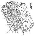
- a manifolded assembly of motorized valves is indicated generally at 20 and includes a manifold block 22 having a plurality of motorized valves in the form of solenoid valves 24, 26, 28, 30, 32, 34, 36 mounted on the block 22 and having ports such as those denoted by reference numerals 33, 35 in FIG. 5 for valving flow through selected passages in the block.
- the manifold block has a plurality of valving passages provided on the under side of the block 22 in a somewhat labyrinth arrangement as denoted typically by reference numeral 38.
- the passages 38 are arranged so as to communicate individually with selected ones of the ports of the individual solenoid valves 24, 26, 28, 30, 32, 34, 36 to provide the desired flow to the selected passage upon energization of any of the solenoid valves.
- Such an arrangement is known in the art of automatic transmission design.
- the filter/gasket 10 is disposed over the passages 38 in the manifold blocks 22; and, a separator plate having the desired arrangement and location of flow passages thereon, as denoted by reference numerals 40, is received over the filter/gasket 10.
- Separator plate 42 is secured there over by any suitable expedient as for example clamping with another plate or by threaded fasteners through appropriate holes provided in the manifold block 22 and plate 42, which fasteners have not been illustrated for the sake of simplicity.
- the undersurface of block 22 has formed therein a plurality of grooves 44 into which is received the upper bead portion 16 of filter/gasket 10.
- the upper portion 160 of the embodiment of FIG. 6; the upper portion 260 of the embodiment of FIG. 7 and the upper portion 360 of the embodiment of FIG. 9 would also be received in the groove 44.
- various forms of the bead in the embodiment 10, 140, 240 and 340 have been illustrated, it will be understood that the bead transverse section may be varied as required for any particular sealing requirements. It will also be understood that elastomeric material other than that described herein may be employed as dictated by the sealing requirements for the particular hydraulic fluid.
- the present invention thus provides a unique and novel combination filter/gasket for use in a manifolded arrangement of solenoid valve employed for controlling hydraulic fluid flow in automatic car transmissions used in automotive applications.
Landscapes
- Engineering & Computer Science (AREA)
- Physics & Mathematics (AREA)
- Fluid Mechanics (AREA)
- Mechanical Engineering (AREA)
- General Engineering & Computer Science (AREA)
- Chemical & Material Sciences (AREA)
- Chemical Kinetics & Catalysis (AREA)
- Valve Housings (AREA)
- General Details Of Gearings (AREA)
- Gasket Seals (AREA)
- Lift Valve (AREA)
Claims (7)
- Verzweigungs- und Ventilvorrichtung (20) zu der gehören:(a) ein Verzweigungsblock (22) mit mehreren Einlasskanälen (33,35) und mehreren Auslasskanälen (33,35);(b) antriebsgesteuerte Ventilmittel (24...36), die an dem Verzweigungsblock (22) angeordnet sind und dazu dienen, auf Betätigung hin die Strömung zwischen den Ein- und Auslasskanälen (33,35) selektiv zu steuern;(c) eine Trennplatte (42) mit mehreren darin ausgebildeten Öffnungen (40), die über den Einlasskanälen und Auslasskanälen (33,35) zu liegen kommen, wobei die Öffnungen (40) der Trennplatte (42) mit ausgewählten der Einlassanschlüsse und Auslassanschlüsse (33,35) strömungsmäßig verbunden sind; gekennzeichnet durch(d) ein Filter-/Dichtungsmittel (10), das zwischen der Trennplatte (42) und dem Verzweigungsblock (22) eingefügt ist und zu dem gehören:(i) ein aus gewebtem Siebmaterial gefertigtes Gitter (12);(ii) ein Wulst (14,140,240,340), der geeignet angelegt ist, um ausgewählte der Öffnungen (40) zu isolieren, wobei der Wulst (14,140,240,340) aus einem elastomeren Werkstoff gefertigt ist, der sich durch das Gitter (12) hindurch erstreckt und erste und zweite Abschnitte (16,18,160,180,260, 280,360,380) des Wulstes (14,140,240,340) auf entgegengesetzten Seiten des Gitters (12) an einer gemeinsamen Position darauf bildet.
- Anordnung nach Anspruch 1, bei der der Wulst (14,140,240,340) aus einem Werkstoff gefertigt ist, der aus der Gruppe ausgewählt ist, die auf (a) Silikonelastomer oder (b) Fluorkohlenstoffelastomer basiert.
- Anordnung nach Anspruch 1, bei der das Gitter (12) aus einem Werkstoff gefertigt ist, der aus der Gruppe ausgewählt ist, die auf (a) rostfreien Stahl oder (b) Polyesterkunststoff basiert.
- Anordnung nach Anspruch 1, bei der der Wulst (14,140,240,340) aus einem elastomeren Werkstoff mit einer Härte im Bereich 72-78, gemessen nach der Shore-Härteskala "A", gefertigt ist.
- Anordnung nach Anspruch 1, bei der die ersten Abschnitte (16,18,160,180,260,280,360,380) des Wulstes (14,140,240,340) einen im Wesentlichen halbkreisförmigen Querschnitt aufweisen.
- Anordnung nach Anspruch 1, bei der die zweiten Abschnitte (16,18,160,180,260,280,360,380) des Wulstes (14,140,240,340) im Querschnitt eine im Wesentlichen rechteckige Gestalt aufweisen.
- Anordnung nach Anspruch 1, bei der zu den antriebsgesteuerten Ventilmitteln (24...36) wenigstens ein elektromagnetisch betätigtes Ventil gehört.
Applications Claiming Priority (2)
| Application Number | Priority Date | Filing Date | Title |
|---|---|---|---|
| US639916 | 1996-04-24 | ||
| US08/639,916 US5680883A (en) | 1996-04-24 | 1996-04-24 | Manifold and valve assembly and filter/gasket therefor |
Publications (3)
| Publication Number | Publication Date |
|---|---|
| EP0803654A2 EP0803654A2 (de) | 1997-10-29 |
| EP0803654A3 EP0803654A3 (de) | 1999-07-07 |
| EP0803654B1 true EP0803654B1 (de) | 2003-04-02 |
Family
ID=24566101
Family Applications (1)
| Application Number | Title | Priority Date | Filing Date |
|---|---|---|---|
| EP97106137A Expired - Lifetime EP0803654B1 (de) | 1996-04-24 | 1997-04-15 | Mehrfachventil und Filter/Abdichtung dafür |
Country Status (5)
| Country | Link |
|---|---|
| US (1) | US5680883A (de) |
| EP (1) | EP0803654B1 (de) |
| CA (1) | CA2201952A1 (de) |
| DE (1) | DE69720312T2 (de) |
| ES (1) | ES2193292T3 (de) |
Families Citing this family (29)
| Publication number | Priority date | Publication date | Assignee | Title |
|---|---|---|---|---|
| FR2757599B1 (fr) * | 1996-12-23 | 1999-01-29 | Ksb Sa | Actionneur de robinet dans lequel la base du boitier est conformee de maniere a assurer les liaisons de distribution du fluide |
| DE19757865C1 (de) * | 1997-12-24 | 1999-06-17 | Porsche Ag | Anschlußeinrichtung für hydraulisches Steuergerät aus Leichtmetall |
| US6502601B2 (en) * | 1998-03-05 | 2003-01-07 | Swagelok Company | Modular surface mount manifold assemblies |
| US6644353B1 (en) | 1998-03-05 | 2003-11-11 | Swagelok Company | Modular surface mount manifold |
| US7036528B2 (en) | 1998-05-18 | 2006-05-02 | Swagelok Company | Modular surface mount manifold assemblies |
| CA2365467A1 (en) | 1999-04-19 | 2000-10-26 | International Engine Intellectual Property Company, Llc | Hydraulic system with a combination filter screen and gasket |
| DE10012067C1 (de) * | 2000-03-06 | 2001-09-27 | Rexroth Mecman Stockholm Ab | Mehrwegeventil (hygienische Dichtungsplatte) |
| US20060070674A1 (en) * | 2004-10-01 | 2006-04-06 | Eidsmore Paul G | Substrate with offset flow passage |
| US7960165B2 (en) * | 2005-12-01 | 2011-06-14 | James Wright | Method and apparatus for drying organic material |
| US20080089044A1 (en) * | 2006-10-16 | 2008-04-17 | Raybestos Powertrain, Llc | Spacer block for rebuilt electrically operated automatic transmission controller assembly |
| US20080128993A1 (en) * | 2006-11-30 | 2008-06-05 | Freudenberg-Nok General Partnership | Bonded Filter Gasket With Raised Sealing Beads |
| DE102007019946A1 (de) | 2007-04-27 | 2008-10-30 | Elringklinger Ag | Flachdichtung und Verfahren zur Herstellung einer Flachdichtung |
| EP2039963B1 (de) * | 2007-09-19 | 2010-12-08 | Carl Freudenberg KG | Separatorplatte |
| WO2010033827A1 (en) | 2008-09-18 | 2010-03-25 | Advanced Powertrain Engineering, Llc | Printed circuit assembly for a solenoid module for an automatic transmission |
| WO2010053705A1 (en) * | 2008-11-10 | 2010-05-14 | Delphi Technologies, Inc. | Single piece gasket |
| DE102008062829B4 (de) | 2008-12-23 | 2013-06-13 | Reinz-Dichtungs-Gmbh | Hydrauliksystemsteuerplatte |
| CA2717752C (en) * | 2009-10-15 | 2018-01-23 | Advanced Powertrain Engineering, Llc | Method of rebuilding solenoids for automatic transmissions |
| JP5365552B2 (ja) * | 2010-03-09 | 2013-12-11 | マツダ株式会社 | 自動変速機の制御装置 |
| DE202010006768U1 (de) | 2010-05-12 | 2010-08-05 | Reinz-Dichtungs-Gmbh | Metallische Flachdichtung |
| DE102010030072A1 (de) * | 2010-06-15 | 2011-12-15 | Federal-Mogul Sealing Systems Gmbh | Statistische Dichtung mit integriertem Sieb- oder Filterelement |
| DE202011004993U1 (de) | 2011-04-07 | 2012-04-10 | Reinz-Dichtungs-Gmbh | Flachdichtung mit kalandrierter Siebgewebelage |
| DE202013007241U1 (de) * | 2013-08-12 | 2014-10-06 | Reinz-Dichtungs-Gmbh | Flachdichtung |
| DE202013010604U1 (de) * | 2013-11-23 | 2014-11-24 | Reinz-Dichtungs-Gmbh | Steuerungssystem |
| US9970533B2 (en) | 2013-11-27 | 2018-05-15 | Advanced Powertrain Engineering, Llc | Solenoid rebuilding method for automatic transmissions |
| DE202016101613U1 (de) | 2016-03-23 | 2017-06-28 | Reinz-Dichtungs-Gmbh | Getriebesystemsteuerplatte und Getriebesteuersystem |
| DE202016102266U1 (de) * | 2016-04-28 | 2017-07-31 | Reinz-Dichtungs-Gmbh | Hydrauliksystemsteuerplatte |
| DE102016215154B4 (de) | 2016-08-15 | 2025-02-20 | Festo Se & Co. Kg | Abdichtungssystem |
| DE102019125893A1 (de) * | 2019-09-26 | 2021-04-01 | Wabco Europe Bvba | Getriebesteuereinheit |
| KR20210132921A (ko) * | 2020-04-28 | 2021-11-05 | 주식회사 아모그린텍 | 중력식 정수장치용 필터모듈 및 이를 포함하는 중력식 정수장치 |
Family Cites Families (9)
| Publication number | Priority date | Publication date | Assignee | Title |
|---|---|---|---|---|
| US3701360A (en) * | 1971-06-03 | 1972-10-31 | Culligan Int Co | Water softener valve |
| US3788484A (en) * | 1971-08-23 | 1974-01-29 | Coulter Electronics | Inline fluid filter |
| FR2398245A1 (fr) * | 1977-07-22 | 1979-02-16 | Outillage Air Comprime | Perfectionnement a un distributeur pneumatique sur embase |
| US4210034A (en) * | 1977-08-15 | 1980-07-01 | Younger Gilbert W | Channel plate for automatic transmissions |
| FR2615270B1 (fr) * | 1987-05-15 | 1989-07-13 | Air Liquide | Detendeur pour gaz purs |
| JP2714381B2 (ja) * | 1987-09-14 | 1998-02-16 | アイシン・エィ・ダブリュ株式会社 | セパレートプレート及びその製造方法 |
| US5456475A (en) * | 1988-04-28 | 1995-10-10 | Skf Usa Inc. | Protected seal assembly and protective filter unit therefor |
| DE4240467A1 (en) * | 1991-12-13 | 1993-06-17 | Volkswagen Ag | Seal for fluid channel between two structural parts - has recess housing relaxed ring seal with radial play allowing deformation for sealing action |
| US5314616A (en) * | 1992-10-29 | 1994-05-24 | Ford Motor Company | Partial flow filter system for an automatic power transmission mechanism |
-
1996
- 1996-04-24 US US08/639,916 patent/US5680883A/en not_active Expired - Fee Related
-
1997
- 1997-04-04 CA CA002201952A patent/CA2201952A1/en not_active Abandoned
- 1997-04-15 DE DE69720312T patent/DE69720312T2/de not_active Expired - Fee Related
- 1997-04-15 EP EP97106137A patent/EP0803654B1/de not_active Expired - Lifetime
- 1997-04-15 ES ES97106137T patent/ES2193292T3/es not_active Expired - Lifetime
Also Published As
| Publication number | Publication date |
|---|---|
| ES2193292T3 (es) | 2003-11-01 |
| US5680883A (en) | 1997-10-28 |
| EP0803654A3 (de) | 1999-07-07 |
| CA2201952A1 (en) | 1997-10-24 |
| EP0803654A2 (de) | 1997-10-29 |
| DE69720312D1 (de) | 2003-05-08 |
| DE69720312T2 (de) | 2004-02-12 |
Similar Documents
| Publication | Publication Date | Title |
|---|---|---|
| EP0803654B1 (de) | Mehrfachventil und Filter/Abdichtung dafür | |
| US6715510B2 (en) | Electro-hydraulic controller for automatic transmissions | |
| JP3663463B2 (ja) | 弁座内のハードなチューブの流体チャンネルとフレシブルな密封ダイアフラムとを有するソレノイドバルブ | |
| EP0485815B1 (de) | Dichtung für Ölwanne und ähnliches | |
| EP0797008B1 (de) | Magnetventilverteileranordnung | |
| EP1508731B1 (de) | Elektromagnetventil und Herstellungsverfahren | |
| US4319607A (en) | Valve assembly and valve sealing element | |
| EP1366790B1 (de) | Einteilige Filterkartusche mit röhrenförmigem Filtermaterial und angegossenen Ring- und Axialrippen | |
| US4499916A (en) | Vacuum check valve | |
| US20260054707A1 (en) | A solenoid valve of a normal closed type with an integrated check valve | |
| EP0293646B1 (de) | Baugruppe aus mehreren unabhängig voneinander elektromagnetisch schaltbaren Wegeventilen | |
| US20040238422A1 (en) | Filter apparatus and associated method | |
| KR20200076638A (ko) | 자동차 변속기에서 작동 요소들의 동작을 위한 유압 동작 장치 | |
| US4756233A (en) | Air filter system for a vacuum actuator | |
| JPS59155647A (ja) | 自動変速機のオイルフイルタ− | |
| US3901964A (en) | Method of making a plastic butterfly valve vane with peripheral seal | |
| JP2004052820A (ja) | バルブボディ一体型フィルタ及びその製造方法 | |
| EP0435545A1 (de) | Verbesserungen bezüglich auswechselbarer Filtereinheiten | |
| US20240167578A1 (en) | Modular manifold for use with a microfluidics chip and having two-way and three-way plate manifolds and method of making the same | |
| US20230167901A1 (en) | Functional element with filter portion | |
| EP1134429B1 (de) | Eine Stütz- und Verteilungsvorrichtung eines pneumatischen Ventils | |
| US20260085763A1 (en) | Vent valve and vehicle battery pack having the same | |
| JPS61157317A (ja) | オイルフイルタ | |
| SU1170212A1 (ru) | Регулирующее устройство | |
| CN118475785A (zh) | 流体密封系统、流体回路和方法 |
Legal Events
| Date | Code | Title | Description |
|---|---|---|---|
| PUAI | Public reference made under article 153(3) epc to a published international application that has entered the european phase |
Free format text: ORIGINAL CODE: 0009012 |
|
| AK | Designated contracting states |
Kind code of ref document: A2 Designated state(s): DE ES FR GB IT |
|
| PUAL | Search report despatched |
Free format text: ORIGINAL CODE: 0009013 |
|
| AK | Designated contracting states |
Kind code of ref document: A3 Designated state(s): DE ES FR GB IT |
|
| 17P | Request for examination filed |
Effective date: 19990727 |
|
| 17Q | First examination report despatched |
Effective date: 20010315 |
|
| GRAH | Despatch of communication of intention to grant a patent |
Free format text: ORIGINAL CODE: EPIDOS IGRA |
|
| GRAH | Despatch of communication of intention to grant a patent |
Free format text: ORIGINAL CODE: EPIDOS IGRA |
|
| GRAA | (expected) grant |
Free format text: ORIGINAL CODE: 0009210 |
|
| AK | Designated contracting states |
Designated state(s): DE ES FR GB IT |
|
| REG | Reference to a national code |
Ref country code: GB Ref legal event code: FG4D |
|
| REF | Corresponds to: |
Ref document number: 69720312 Country of ref document: DE Date of ref document: 20030508 Kind code of ref document: P |
|
| ET | Fr: translation filed | ||
| REG | Reference to a national code |
Ref country code: ES Ref legal event code: FG2A Ref document number: 2193292 Country of ref document: ES Kind code of ref document: T3 |
|
| PLBE | No opposition filed within time limit |
Free format text: ORIGINAL CODE: 0009261 |
|
| STAA | Information on the status of an ep patent application or granted ep patent |
Free format text: STATUS: NO OPPOSITION FILED WITHIN TIME LIMIT |
|
| PGFP | Annual fee paid to national office [announced via postgrant information from national office to epo] |
Ref country code: GB Payment date: 20040312 Year of fee payment: 8 |
|
| 26N | No opposition filed |
Effective date: 20040105 |
|
| PGFP | Annual fee paid to national office [announced via postgrant information from national office to epo] |
Ref country code: FR Payment date: 20040402 Year of fee payment: 8 |
|
| PGFP | Annual fee paid to national office [announced via postgrant information from national office to epo] |
Ref country code: ES Payment date: 20040423 Year of fee payment: 8 |
|
| PGFP | Annual fee paid to national office [announced via postgrant information from national office to epo] |
Ref country code: DE Payment date: 20040430 Year of fee payment: 8 |
|
| PG25 | Lapsed in a contracting state [announced via postgrant information from national office to epo] |
Ref country code: IT Free format text: LAPSE BECAUSE OF NON-PAYMENT OF DUE FEES;WARNING: LAPSES OF ITALIAN PATENTS WITH EFFECTIVE DATE BEFORE 2007 MAY HAVE OCCURRED AT ANY TIME BEFORE 2007. THE CORRECT EFFECTIVE DATE MAY BE DIFFERENT FROM THE ONE RECORDED. Effective date: 20050415 Ref country code: GB Free format text: LAPSE BECAUSE OF NON-PAYMENT OF DUE FEES Effective date: 20050415 |
|
| PG25 | Lapsed in a contracting state [announced via postgrant information from national office to epo] |
Ref country code: ES Free format text: LAPSE BECAUSE OF NON-PAYMENT OF DUE FEES Effective date: 20050416 |
|
| PG25 | Lapsed in a contracting state [announced via postgrant information from national office to epo] |
Ref country code: DE Free format text: LAPSE BECAUSE OF NON-PAYMENT OF DUE FEES Effective date: 20051101 |
|
| GBPC | Gb: european patent ceased through non-payment of renewal fee |
Effective date: 20050415 |
|
| PG25 | Lapsed in a contracting state [announced via postgrant information from national office to epo] |
Ref country code: FR Free format text: LAPSE BECAUSE OF NON-PAYMENT OF DUE FEES Effective date: 20051230 |
|
| REG | Reference to a national code |
Ref country code: FR Ref legal event code: ST Effective date: 20051230 |
|
| REG | Reference to a national code |
Ref country code: ES Ref legal event code: FD2A Effective date: 20050416 |