EP0803639B1 - Système à compresseur et détendeur à vis - Google Patents
Système à compresseur et détendeur à vis Download PDFInfo
- Publication number
- EP0803639B1 EP0803639B1 EP19960201149 EP96201149A EP0803639B1 EP 0803639 B1 EP0803639 B1 EP 0803639B1 EP 19960201149 EP19960201149 EP 19960201149 EP 96201149 A EP96201149 A EP 96201149A EP 0803639 B1 EP0803639 B1 EP 0803639B1
- Authority
- EP
- European Patent Office
- Prior art keywords
- motor
- compressor
- outlet
- expander
- rotors
- Prior art date
- Legal status (The legal status is an assumption and is not a legal conclusion. Google has not performed a legal analysis and makes no representation as to the accuracy of the status listed.)
- Expired - Lifetime
Links
- 230000006835 compression Effects 0.000 claims description 5
- 238000007906 compression Methods 0.000 claims description 5
- 238000010438 heat treatment Methods 0.000 claims description 5
- 238000001816 cooling Methods 0.000 claims description 3
- 238000004519 manufacturing process Methods 0.000 claims description 3
- 239000003570 air Substances 0.000 claims 1
- 239000012080 ambient air Substances 0.000 claims 1
- 238000010276 construction Methods 0.000 description 4
- 239000000446 fuel Substances 0.000 description 4
- 230000002349 favourable effect Effects 0.000 description 3
- 230000007423 decrease Effects 0.000 description 2
- 238000006073 displacement reaction Methods 0.000 description 1
- 230000005611 electricity Effects 0.000 description 1
- 230000002459 sustained effect Effects 0.000 description 1
Images


Classifications
-
- F—MECHANICAL ENGINEERING; LIGHTING; HEATING; WEAPONS; BLASTING
- F01—MACHINES OR ENGINES IN GENERAL; ENGINE PLANTS IN GENERAL; STEAM ENGINES
- F01C—ROTARY-PISTON OR OSCILLATING-PISTON MACHINES OR ENGINES
- F01C11/00—Combinations of two or more machines or engines, each being of rotary-piston or oscillating-piston type
- F01C11/002—Combinations of two or more machines or engines, each being of rotary-piston or oscillating-piston type of similar working principle
- F01C11/004—Combinations of two or more machines or engines, each being of rotary-piston or oscillating-piston type of similar working principle and of complementary function, e.g. internal combustion engine with supercharger
-
- F—MECHANICAL ENGINEERING; LIGHTING; HEATING; WEAPONS; BLASTING
- F04—POSITIVE - DISPLACEMENT MACHINES FOR LIQUIDS; PUMPS FOR LIQUIDS OR ELASTIC FLUIDS
- F04C—ROTARY-PISTON, OR OSCILLATING-PISTON, POSITIVE-DISPLACEMENT MACHINES FOR LIQUIDS; ROTARY-PISTON, OR OSCILLATING-PISTON, POSITIVE-DISPLACEMENT PUMPS
- F04C18/00—Rotary-piston pumps specially adapted for elastic fluids
- F04C18/08—Rotary-piston pumps specially adapted for elastic fluids of intermeshing-engagement type, i.e. with engagement of co-operating members similar to that of toothed gearing
- F04C18/12—Rotary-piston pumps specially adapted for elastic fluids of intermeshing-engagement type, i.e. with engagement of co-operating members similar to that of toothed gearing of other than internal-axis type
- F04C18/14—Rotary-piston pumps specially adapted for elastic fluids of intermeshing-engagement type, i.e. with engagement of co-operating members similar to that of toothed gearing of other than internal-axis type with toothed rotary pistons
- F04C18/16—Rotary-piston pumps specially adapted for elastic fluids of intermeshing-engagement type, i.e. with engagement of co-operating members similar to that of toothed gearing of other than internal-axis type with toothed rotary pistons with helical teeth, e.g. chevron-shaped, screw type
- F04C18/165—Rotary-piston pumps specially adapted for elastic fluids of intermeshing-engagement type, i.e. with engagement of co-operating members similar to that of toothed gearing of other than internal-axis type with toothed rotary pistons with helical teeth, e.g. chevron-shaped, screw type having more than two rotary pistons with parallel axes
-
- F—MECHANICAL ENGINEERING; LIGHTING; HEATING; WEAPONS; BLASTING
- F02—COMBUSTION ENGINES; HOT-GAS OR COMBUSTION-PRODUCT ENGINE PLANTS
- F02B—INTERNAL-COMBUSTION PISTON ENGINES; COMBUSTION ENGINES IN GENERAL
- F02B55/00—Internal-combustion aspects of rotary pistons; Outer members for co-operation with rotary pistons
- F02B55/14—Shapes or constructions of combustion chambers
Definitions
- a motor is known from e.g. WO 90/04107 which comprises a compressor and an expander. Gas compressed in the compressor is heated and fed to the expander. The compressor is coupled to the expander, whereby the compressor is driven with the expansion energy.
- the invention has for its object to provide such a motor which can take a compact form and has a simple basic construction.
- the production costs of the motor according to the invention can remain comparatively low by applying the step of claim 2.
- a very favourable further development is characterized in claim 3.
- a hot gas motor/compressor unit is hereby obtained which can function independently.
- the air partially expanded in the expander is stored as compressed air in the pressure reservoir. If the compressed air can be used immediately, i.e. without first cooling, a comparatively high efficiency can be achieved.
- the step of claim 4 is preferably applied.
- the gas herein circulates in a closed circuit so that a gas can be chosen that is suitable for the intended application, in particular a freon type.
- the gas cooling device results in a low pressure of the gas in the connecting channel between the expander outlet, which favours a high efficiency of the device.
- the step of claim 5 is applied.
- the compressor hereby acquires a very low dead volume, whereby a high pressure can be reached in one stage. This is particularly favourable in the application as motor compressor unit.
- step of claim 6 is applied.
- a high pressure can be created in the connecting channel.
- the non-return valve prevents gas under high pressure flowing back to the compressor. Up to the point where the gas is sufficiently compressed in the compressor it is pressed into the connecting channel.
- step of claim 8 results in a suitable form of the profiles of the rotors, which particularly enables a high compression with a low dead volume.
- a suitable step is characterized in claim 9.
- the motor can be used at any random location where one fuel or another is available. It can thus be provided with a reservoir with its own fuel supply or be coupled to the gas main.
- the burner can of course be adapted to the type of fuel.
- step of claim 10 is applied. As the load increases the rotation speed of the motor will tend to fall. In that case the heat production is increased by the control device whereby more power is supplied and the rotation speed remains substantially unchanged.
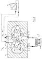
- the hot gas motor 1 shown in fig. 1 comprises a housing 2 in which three mutually overlapping cylindrical bores are formed. In the central, smaller bore a female rotor 4 is rotatably mounted and in the two other bores male rotors 3 and 5 respectively are likewise rotatably mounted.
- Rotors 3-5 are coupled such that they rotate at equal rotation speed in the direction indicated with the arrows.
- the female rotor 4 therefore rotates in a direction opposed to that of the male rotors.
- the rotors have a profile such that except for a very small gap they are in mutual contact in any rotational position.
- a displacement system is hereby formed. This is generally known per se, as for instance from the European patent specification 0 211 826.
- the compressor stage has an inlet 6 through which gas can flow to the chamber 7. Due to the rotation of rotor 3 this gas is carried along counter-clockwise into the chamber position designated with 8. Due to the co-action of the rotors 3 and 4 the gas present in chamber 8 is subsequently compressed and discharged via the outlet conduit 9. A non-return valve 10 is arranged in this conduit. With an embodiment of the rotors as will be further elucidated below with reference to fig. 4, a high compression factor can be obtained.
- the highly compressed gas is heated in a schematically designated heat exchanger 11 whereby the volume of the compressed quantity of gas increases.
- the thus heated gas is guided via inlet conduit 12 to the high pressure side 13 of the expander stage.
- the rotor 5 is urged by this high pressure in the direction indicated with the arrow, wherein the gas is transported to the outlet chamber 14 of the expander.
- a lower pressure prevails in the expander chamber 14 since this is connected to the inlet 6 of the compressor.
- the outlet 15 of the expander is connected via a conduit 16 to a cooler 17 which further cools the gas already cooled by the expansion.
- the outlet of cooler 17 is connected via conduit 18 to the inlet 6 of the compressor.
- a non-return valve can likewise be accommodated in the outlet of the expander.
- a controlled valve can be accommodated in the inlet conduit 12 of the expander in order to obtain a dosage of the quantity of gas fed to the expander.
- a suitable gas for use in a hot gas motor as in fig. 1 is for instance freon.
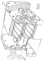
- Fig. 2 shows a partly schematic perspective view with broken away parts of the device 1.
- Housing 2 has a block shape and is closed at both ends with covers 20, 21 in which the rotors 3-5 are mounted.
- covers 20, 21 in which the rotors 3-5 are mounted.
- Tooth wheels 22 mounted on the ends of the rotors 3-5 protruding outside cover 21 are tooth wheels 22 which are in mutual engagement. Tooth wheels 22 all have the same number of teeth, whereby the described desired rotation ratio is achieved.
- a generator 23 can for instance be coupled to motor 1 to generate electricity.
- the heating device is not shown in detail in fig. 2 but may comprise a random burner, so that an easily available fuel can be used to drive the generator.
- control can take place in suitable manner on the basis of the rotation speed.
- the control device will be embodied such that when the rotation speed decreases the heat supply is increased and vice versa.
- a substantially constant rotation speed can hereby be sustained.
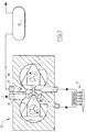
- Fig. 4 shows profiles which are generally very suitable for the invention.
- the male rotors 30 and 31 co-act with an oppositely rotating female rotor 32.
- each of the male rotors 30, 31 and the female rotor 32 are profiled such that, in the positions in which a protruding part of a male rotor co-acts with a recessed part of a female rotor, these rotors are in mutual contact along two lines.
- formed between the male rotor and the female rotor is a chamber 36 which decreases to a very small volume.
- the transported gas can hereby be compressed to a high pressure and discharged with this high pressure via the delivery port 30 shown with dashed lines.
- the width of the groove 34 in the female rotor 32 is smaller than the width 35 of the bridge, i.e. the remaining part of the cylindrical bore for the female rotor 32. This prevents a short circuit occurring between the compressor inlet and the expander outlet.
- a quantity of heated gas under high pressure will be carried via the "lower" recess of the female rotor in the direction toward the compressor stage.
- This air under high pressure is preferably discharged via a conduit 37, the entrance to which is only left clear when the lower groove in the female rotor 32 is wholly in contact with the lower bridge 38, so that no undesired leakage from the first expander chamber to the discharge 37 can occur.
- Conduit 37 is connected to the low pressure side of the system via a conduit in which is accommodated a controlled valve.
- a heat exchanger Preferably also accommodated in this conduit 37 is a heat exchanger through the other side of which flows the gas compressed under high pressure from the outlet of the compressor.
- the invention is not limited to an embodiment with two male rotors and a female rotor.
- three male rotors 41, 42, 43 can also co-act with a female rotor 44.
- Equal rotation speeds are applied forcibly in the directions indicated with arrows by a suitable toothed gearing 45.
- the additional third stage can be embodied as additional compression or additional expansion stage.
- the extra stage can thus be arranged in a position corresponding with the "underside" of the female rotor 32 in fig. 4 in order to cause the gas under high pressure transported via the groove in this female rotor to expand in this extra stage so that the efficiency of the device is increased.
- the profile of the rotors can be straight, as shown in fig. 2, or helical as shown in fig. 5. As noted above, these embodiments are per se known.
- the female rotor has the same rotation speed as the male rotors, this is not essential for the invention.
- the female rotor can have a larger number of recesses than the male rotors have protrusions in order to obtain a construction which is optimal for the intended application and the available space.
- the diameter of the female rotor have to be smaller than that of the male rotors.
- the female rotor it will be appropriate for the female rotor to have a larger diameter.
Landscapes
- Engineering & Computer Science (AREA)
- Mechanical Engineering (AREA)
- General Engineering & Computer Science (AREA)
- Chemical & Material Sciences (AREA)
- Combustion & Propulsion (AREA)
- Applications Or Details Of Rotary Compressors (AREA)
Claims (10)
- Moteur à gaz chaud comportant un compresseur ayant une entrée et une sortie, un mécanisme d'expansion ayant une entrée et une sortie, dans lequel la sortie du compresseur et l'entrée du mécanisme d'expansion sont reliées mutuellement par un canal de liaison comportant un dispositif de chauffage de gaz, dans lequel le compresseur est du type rotatif ayant au moins un rotor mâle monté dans une première chambre cylindrique d'un boítier et ayant un profil ayant des parties en saillie, qui coopère avec un rotor femelle qui a un profil ayant des cavités coagissant avec celles-ci et qui est monté dans une seconde chambre cylindrique recoupant la première chambre cylindrique et dans laquelle le mécanisme d'expansion est formé par le rotor femelle et au moins un second rotor mâle monté dans une troisième chambre cylindrique et ayant un profil muni de parties en saillie coagissant avec celui-ci, et dans lequel les rotors sont mutuellement reliés pour tourner.
- Moteur selon la revendication 1, dans lequel tous les rotors mâles sont identiques.
- Moteur selon la revendication 1 ou 2, dans lequel l'entrée de compresseur est reliée à l'environnement afin de prendre de l'air ambiant et la sortie du mécanisme d'expansion est reliée à un réservoir sous pression d'air comprimé.
- Moteur selon la revendication 1 ou 2, dans lequel la sortie du mécanisme d'expansion et l'entrée du compresseur sont mutuellement reliées par un canal de liaison comportant un dispositif de refroidissement de gaz.
- Moteur selon l'une quelconque des revendications précédentes, dans lequel les rotors de compresseur sont profilés de telle sorte qu'ils sont en contact mutuel le long de deux lignes au moins proches de la position correspondant à l'extrémité d'une course de compression et en ce que la sortie de compresseur comporte un orifice de sortie situé dans une paroi du boítier contre laquelle se trouve une surface d'extrémités de tête du rotor femelle, lequel orifice de sortie s'étend dans une zone qui est traversée par les deux rotors de compresseur femelle et mâle.
- Moteur selon l'une quelconque des revendications précédentes, dans lequel un clapet antiretour permettant un écoulement à partir de la sortie de compresseur vers l'entrée du mécanisme d'expansion est reçu dans le canal de liaison contenant le dispositif de chauffage de gaz.
- Moteur selon l'une quelconque des revendications précédentes, dans lequel les parties en saillie des rotors mâles ont une surface d'extrémité cylindrique coagissant avec la paroi de la chambre cylindrique.
- Moteur selon l'une quelconque des revendications précédentes, dans lequel le nombre de parties en saillie du rotor ou des rotors mâles est égal au nombre de cavités du rotor femelle de sorte que pendant un fonctionnement, ceux-ci tournent avec la même vitesse de rotation.
- Moteur selon l'une quelconque des revendications précédentes, dans lequel le dispositif de chauffage est constitué d'un brûleur.
- Moteur selon l'une quelconque des revendications précédentes, comportant un dispositif de commande qui ajuste la production de chaleur du dispositif de chauffage conformément à la vitesse de rotation de moteur prévue.
Priority Applications (2)
| Application Number | Priority Date | Filing Date | Title |
|---|---|---|---|
| EP19960201149 EP0803639B1 (fr) | 1996-04-26 | 1996-04-26 | Système à compresseur et détendeur à vis |
| DE1996622841 DE69622841T2 (de) | 1996-04-26 | 1996-04-26 | Schraubenrotor-Verdichter-Entspanner-Einheit |
Applications Claiming Priority (1)
| Application Number | Priority Date | Filing Date | Title |
|---|---|---|---|
| EP19960201149 EP0803639B1 (fr) | 1996-04-26 | 1996-04-26 | Système à compresseur et détendeur à vis |
Publications (2)
| Publication Number | Publication Date |
|---|---|
| EP0803639A1 EP0803639A1 (fr) | 1997-10-29 |
| EP0803639B1 true EP0803639B1 (fr) | 2002-08-07 |
Family
ID=8223936
Family Applications (1)
| Application Number | Title | Priority Date | Filing Date |
|---|---|---|---|
| EP19960201149 Expired - Lifetime EP0803639B1 (fr) | 1996-04-26 | 1996-04-26 | Système à compresseur et détendeur à vis |
Country Status (2)
| Country | Link |
|---|---|
| EP (1) | EP0803639B1 (fr) |
| DE (1) | DE69622841T2 (fr) |
Families Citing this family (4)
| Publication number | Priority date | Publication date | Assignee | Title |
|---|---|---|---|---|
| DE10123078C1 (de) * | 2001-05-11 | 2002-05-23 | Ulrich Zuberbuehler | Heißgasmotor mit Schraubenrotor |
| IL164057A0 (en) | 2002-03-14 | 2005-12-18 | Newton Propulsion Technologies | Gas turbine engine system |
| IL157666A0 (en) * | 2003-08-31 | 2009-02-11 | Newton Propulsion Technologies Ltd | Novel gas turbine engine system |
| CN115596521A (zh) * | 2022-09-26 | 2023-01-13 | 阜新金昊空压机有限公司(Cn) | 一种回转式气动机 |
Family Cites Families (3)
| Publication number | Priority date | Publication date | Assignee | Title |
|---|---|---|---|---|
| US2481527A (en) * | 1944-06-29 | 1949-09-13 | Jarvis C Marble | Rotary multiple helical rotor machine |
| GB8613414D0 (en) * | 1986-06-03 | 1986-07-09 | Driver R W | Heat transfer systems |
| SE8803595L (sv) * | 1988-10-11 | 1990-04-12 | Svenska Rotor Maskiner Ab | Maskin foer ett gasformigt medium |
-
1996
- 1996-04-26 EP EP19960201149 patent/EP0803639B1/fr not_active Expired - Lifetime
- 1996-04-26 DE DE1996622841 patent/DE69622841T2/de not_active Expired - Lifetime
Also Published As
| Publication number | Publication date |
|---|---|
| DE69622841T2 (de) | 2003-04-10 |
| EP0803639A1 (fr) | 1997-10-29 |
| DE69622841D1 (de) | 2002-09-12 |
Similar Documents
| Publication | Publication Date | Title |
|---|---|---|
| US7249459B2 (en) | Fluid machine for converting heat energy into mechanical rotational force | |
| US6164263A (en) | Quasiturbine zero vibration-continuous combustion rotary engine compressor or pump | |
| JP4014583B2 (ja) | 流体機械 | |
| US4012910A (en) | Thermally driven piston apparatus having an angled cylinder bypass directing fluid into a thermal lag heating chamber beyond the bypass | |
| AU2017200157B2 (en) | Rotary expansible chamber devices having adjustable working-fluid ports, and systems incorporating the same | |
| US5642620A (en) | Hot gas motor and compressor unit | |
| US6877340B2 (en) | Expander | |
| US20050129561A1 (en) | Gapless screw rotor device | |
| KR20120103743A (ko) | 로터리 엔진 | |
| EP0803639B1 (fr) | Système à compresseur et détendeur à vis | |
| US4006595A (en) | Refrigerant-powered engine | |
| US7104061B2 (en) | Fluid machine | |
| JP4079114B2 (ja) | 流体機械 | |
| JPS62502351A (ja) | 流体膨張装置 | |
| US11708832B2 (en) | Cooled dry vacuum screw pump | |
| CA2192714C (fr) | Quasiturbine (qurbine) vibration zero - moteur rotatif a combustion continue, compresseur et pompe | |
| JP4344453B2 (ja) | 回転式流体機械 | |
| JPS6358241B2 (fr) | ||
| KR20020061929A (ko) | 정온배기 로터리 엔진 | |
| CN117988931A (zh) | 一种偏心转子膨胀机 | |
| STOŠIĆ et al. | Combined screw compressor–expander in fuel cell application | |
| HU209428B (en) | Rotary piston engine and internal combustion engine | |
| HK1234119B (zh) | 具有可调节式工作流体端口的旋转可膨胀室装置和结合其的系统 | |
| HUP0402185A2 (en) | Rotary-piston steam engine |
Legal Events
| Date | Code | Title | Description |
|---|---|---|---|
| PUAI | Public reference made under article 153(3) epc to a published international application that has entered the european phase |
Free format text: ORIGINAL CODE: 0009012 |
|
| AK | Designated contracting states |
Kind code of ref document: A1 Designated state(s): DE FR GB NL |
|
| AX | Request for extension of the european patent |
Free format text: LT |
|
| 17P | Request for examination filed |
Effective date: 19980423 |
|
| 17Q | First examination report despatched |
Effective date: 20001128 |
|
| GRAG | Despatch of communication of intention to grant |
Free format text: ORIGINAL CODE: EPIDOS AGRA |
|
| GRAG | Despatch of communication of intention to grant |
Free format text: ORIGINAL CODE: EPIDOS AGRA |
|
| GRAH | Despatch of communication of intention to grant a patent |
Free format text: ORIGINAL CODE: EPIDOS IGRA |
|
| GRAH | Despatch of communication of intention to grant a patent |
Free format text: ORIGINAL CODE: EPIDOS IGRA |
|
| GRAA | (expected) grant |
Free format text: ORIGINAL CODE: 0009210 |
|
| AK | Designated contracting states |
Kind code of ref document: B1 Designated state(s): DE FR GB NL |
|
| REG | Reference to a national code |
Ref country code: GB Ref legal event code: FG4D |
|
| REF | Corresponds to: |
Ref document number: 69622841 Country of ref document: DE Date of ref document: 20020912 |
|
| ET | Fr: translation filed | ||
| PLBE | No opposition filed within time limit |
Free format text: ORIGINAL CODE: 0009261 |
|
| STAA | Information on the status of an ep patent application or granted ep patent |
Free format text: STATUS: NO OPPOSITION FILED WITHIN TIME LIMIT |
|
| 26N | No opposition filed |
Effective date: 20030508 |
|
| PGFP | Annual fee paid to national office [announced via postgrant information from national office to epo] |
Ref country code: DE Payment date: 20120426 Year of fee payment: 17 Ref country code: NL Payment date: 20120503 Year of fee payment: 17 |
|
| PGFP | Annual fee paid to national office [announced via postgrant information from national office to epo] |
Ref country code: FR Payment date: 20120608 Year of fee payment: 17 Ref country code: GB Payment date: 20120427 Year of fee payment: 17 |
|
| REG | Reference to a national code |
Ref country code: NL Ref legal event code: V1 Effective date: 20131101 |
|
| GBPC | Gb: european patent ceased through non-payment of renewal fee |
Effective date: 20130426 |
|
| PG25 | Lapsed in a contracting state [announced via postgrant information from national office to epo] |
Ref country code: DE Free format text: LAPSE BECAUSE OF NON-PAYMENT OF DUE FEES Effective date: 20131101 Ref country code: GB Free format text: LAPSE BECAUSE OF NON-PAYMENT OF DUE FEES Effective date: 20130426 |
|
| REG | Reference to a national code |
Ref country code: FR Ref legal event code: ST Effective date: 20131231 |
|
| REG | Reference to a national code |
Ref country code: DE Ref legal event code: R119 Ref document number: 69622841 Country of ref document: DE Effective date: 20131101 |
|
| PG25 | Lapsed in a contracting state [announced via postgrant information from national office to epo] |
Ref country code: NL Free format text: LAPSE BECAUSE OF NON-PAYMENT OF DUE FEES Effective date: 20131101 Ref country code: FR Free format text: LAPSE BECAUSE OF NON-PAYMENT OF DUE FEES Effective date: 20130430 |