EP0803582B1 - Method of stress inducing transformation of austenite stainless steel and method of producing composite magnetic members - Google Patents
Method of stress inducing transformation of austenite stainless steel and method of producing composite magnetic members Download PDFInfo
- Publication number
- EP0803582B1 EP0803582B1 EP97106468A EP97106468A EP0803582B1 EP 0803582 B1 EP0803582 B1 EP 0803582B1 EP 97106468 A EP97106468 A EP 97106468A EP 97106468 A EP97106468 A EP 97106468A EP 0803582 B1 EP0803582 B1 EP 0803582B1
- Authority
- EP
- European Patent Office
- Prior art keywords
- magnetic
- ferromagnetic
- stress
- intermediately formed
- ironing
- Prior art date
- Legal status (The legal status is an assumption and is not a legal conclusion. Google has not performed a legal analysis and makes no representation as to the accuracy of the status listed.)
- Expired - Lifetime
Links
Images


Classifications
-
- C—CHEMISTRY; METALLURGY
- C21—METALLURGY OF IRON
- C21D—MODIFYING THE PHYSICAL STRUCTURE OF FERROUS METALS; GENERAL DEVICES FOR HEAT TREATMENT OF FERROUS OR NON-FERROUS METALS OR ALLOYS; MAKING METAL MALLEABLE, e.g. BY DECARBURISATION OR TEMPERING
- C21D8/00—Modifying the physical properties of ferrous metals or ferrous alloys by deformation combined with, or followed by, heat treatment
- C21D8/12—Modifying the physical properties of ferrous metals or ferrous alloys by deformation combined with, or followed by, heat treatment during manufacturing of articles with special electromagnetic properties
- C21D8/1294—Modifying the physical properties of ferrous metals or ferrous alloys by deformation combined with, or followed by, heat treatment during manufacturing of articles with special electromagnetic properties involving a localised treatment
-
- C—CHEMISTRY; METALLURGY
- C21—METALLURGY OF IRON
- C21D—MODIFYING THE PHYSICAL STRUCTURE OF FERROUS METALS; GENERAL DEVICES FOR HEAT TREATMENT OF FERROUS OR NON-FERROUS METALS OR ALLOYS; MAKING METAL MALLEABLE, e.g. BY DECARBURISATION OR TEMPERING
- C21D7/00—Modifying the physical properties of iron or steel by deformation
- C21D7/02—Modifying the physical properties of iron or steel by deformation by cold working
-
- C—CHEMISTRY; METALLURGY
- C21—METALLURGY OF IRON
- C21D—MODIFYING THE PHYSICAL STRUCTURE OF FERROUS METALS; GENERAL DEVICES FOR HEAT TREATMENT OF FERROUS OR NON-FERROUS METALS OR ALLOYS; MAKING METAL MALLEABLE, e.g. BY DECARBURISATION OR TEMPERING
- C21D8/00—Modifying the physical properties of ferrous metals or ferrous alloys by deformation combined with, or followed by, heat treatment
-
- H—ELECTRICITY
- H01—ELECTRIC ELEMENTS
- H01F—MAGNETS; INDUCTANCES; TRANSFORMERS; SELECTION OF MATERIALS FOR THEIR MAGNETIC PROPERTIES
- H01F1/00—Magnets or magnetic bodies characterised by the magnetic materials therefor; Selection of materials for their magnetic properties
- H01F1/01—Magnets or magnetic bodies characterised by the magnetic materials therefor; Selection of materials for their magnetic properties of inorganic materials
- H01F1/03—Magnets or magnetic bodies characterised by the magnetic materials therefor; Selection of materials for their magnetic properties of inorganic materials characterised by their coercivity
- H01F1/0302—Magnets or magnetic bodies characterised by the magnetic materials therefor; Selection of materials for their magnetic properties of inorganic materials characterised by their coercivity characterised by unspecified or heterogeneous hardness or specially adapted for magnetic hardness transitions
- H01F1/0306—Metals or alloys, e.g. LAVES phase alloys of the MgCu2-type
-
- C—CHEMISTRY; METALLURGY
- C21—METALLURGY OF IRON
- C21D—MODIFYING THE PHYSICAL STRUCTURE OF FERROUS METALS; GENERAL DEVICES FOR HEAT TREATMENT OF FERROUS OR NON-FERROUS METALS OR ALLOYS; MAKING METAL MALLEABLE, e.g. BY DECARBURISATION OR TEMPERING
- C21D2211/00—Microstructure comprising significant phases
- C21D2211/001—Austenite
-
- C—CHEMISTRY; METALLURGY
- C21—METALLURGY OF IRON
- C21D—MODIFYING THE PHYSICAL STRUCTURE OF FERROUS METALS; GENERAL DEVICES FOR HEAT TREATMENT OF FERROUS OR NON-FERROUS METALS OR ALLOYS; MAKING METAL MALLEABLE, e.g. BY DECARBURISATION OR TEMPERING
- C21D2211/00—Microstructure comprising significant phases
- C21D2211/008—Martensite
-
- C—CHEMISTRY; METALLURGY
- C21—METALLURGY OF IRON
- C21D—MODIFYING THE PHYSICAL STRUCTURE OF FERROUS METALS; GENERAL DEVICES FOR HEAT TREATMENT OF FERROUS OR NON-FERROUS METALS OR ALLOYS; MAKING METAL MALLEABLE, e.g. BY DECARBURISATION OR TEMPERING
- C21D2221/00—Treating localised areas of an article
-
- C—CHEMISTRY; METALLURGY
- C21—METALLURGY OF IRON
- C21D—MODIFYING THE PHYSICAL STRUCTURE OF FERROUS METALS; GENERAL DEVICES FOR HEAT TREATMENT OF FERROUS OR NON-FERROUS METALS OR ALLOYS; MAKING METAL MALLEABLE, e.g. BY DECARBURISATION OR TEMPERING
- C21D7/00—Modifying the physical properties of iron or steel by deformation
- C21D7/02—Modifying the physical properties of iron or steel by deformation by cold working
- C21D7/04—Modifying the physical properties of iron or steel by deformation by cold working of the surface
- C21D7/06—Modifying the physical properties of iron or steel by deformation by cold working of the surface by shot-peening or the like
-
- C—CHEMISTRY; METALLURGY
- C21—METALLURGY OF IRON
- C21D—MODIFYING THE PHYSICAL STRUCTURE OF FERROUS METALS; GENERAL DEVICES FOR HEAT TREATMENT OF FERROUS OR NON-FERROUS METALS OR ALLOYS; MAKING METAL MALLEABLE, e.g. BY DECARBURISATION OR TEMPERING
- C21D8/00—Modifying the physical properties of ferrous metals or ferrous alloys by deformation combined with, or followed by, heat treatment
- C21D8/12—Modifying the physical properties of ferrous metals or ferrous alloys by deformation combined with, or followed by, heat treatment during manufacturing of articles with special electromagnetic properties
- C21D8/1216—Modifying the physical properties of ferrous metals or ferrous alloys by deformation combined with, or followed by, heat treatment during manufacturing of articles with special electromagnetic properties characterised by the working steps
- C21D8/1227—Warm rolling
Definitions
- the present invention relates to a method of producing a composite magnetic member made of a steel material.
- EP 629 711 A1 discloses a method for producing a composite magnetic member by forming an intermediately formed hollow body having a ferromagnetic portion and a non-magnetic portion.
- strain caused by plastic working can be relieved by annealing at or below 500 ° C.
- annealing is not effective in reducing residual tensile stress.
- 10 % or more ironing after forming a ferromagnetic portion by drawing can change the stress such that cracking does not occur.
- the stress can be changed into residual compression strain by 20 % or more ironing.
- the ironing is carried out prior to the non-magnetization of a portion of the magnetic member, because these measurements are for preventing cracks caused by peripheral stress due to the drawing.
- austenite stainless steel is widely used in various fields of railway vehicles to kitchen utensils for domestic use. Therefore, great importance is attached to the mechanical property of austenite stainless steel.
- Concerning austenite stainless steel the following are well known.
- austenite stainless steel is subjected to cold working in a temperature range from the point Ms to the point Md, the martensite phase is generated from the austenite phase which is a mother phase, so that the stress induced-martensite transformation is caused.
- the point Ms is an upper limit temperature at which martensite is generated by the isothermal transformation
- the point Md is an upper limit temperature at which martensite is generated by the stress inducing transformation.
- the above austenite phase is an fcc phase (face centered cubic phase).
- almost all of the above stress induced-martensite phase is composed of an ⁇ ' martensite phase of the bcc phase (body-centered cubic phase), and a very small amount of the ⁇ ' martensite phase of the hcp phase (hexagonal close-packed phase) is contained.
- the stress induced-martensite phase is defined as the aforementioned ⁇ ' martensite phase in this specification, hereinafter.
- the austenite phase stainless steel is a non-magnetic member
- the stress induced-martensite phase stainless steel is a ferromagnetic member, that is, their magnetic properties are greatly different from each other.
- austenite stainless steel when used for a magnetic member or a composite magnetic member described later, it is very effective to increase a ratio of stress induced-ferromagnetic martensite phase.
- the reason why it is impossible to increase the magnetic flax density B 4000 to a high magnetic level not less than 0.8 T (tesla) is considered as follows.
- An amount of strain which can be given to the magnetic member or the composite magnetic member is restricted by the limit at break and the shape of the member. According to the conventional cold working method, even if the maximum strain is given to the magnetic member or the composite magnetic member, a ratio of the generated stress induced-martensite is still low.
- ferromagnetic and non-magnetic portions are integrated with each other.
- ferromagnetic and non-magnetic parts are separately produced, and then they are integrally connected with each other.
- the durability of the connecting portion of the ferromagnetic part with the non-magnetic part is not so high, and further the production cost increases.
- Japanese Unexamined Patent Publication No. 8-3643 discloses a composite magnetic member and a production method thereof in which ferromagnetic and non-magnetic portions are contiguously formed without having a connecting portion.
- the above composite magnetic member can be provided as follows. Austenite alloy steel of a specific composition is used. This austenite alloy steel is subjected to cold working in a predetermined condition so as to generate stress induced-martensite. In this way, the austenite alloy steel is made to be ferromagnetic. After that, desired portions are subjected to solution heat treatment, so that these portions can be made to be non-magnetic.
- a composite magnetic member 6 in which the main body is composed of a ferromagnetic portion 2 and the opening side portion is composed of a non-magnetic portion 3.
- a plate 101 of austenite alloy steel is subjected to pressing by a plurality of times.
- the austenite alloy steel plate 101 is formed into a U-shaped member 106 by cold working. Due to the above cold working, stress induced-martensite is generated in the entire U-shaped member 106. Therefore, the entire U-shaped member 106 becomes ferromagnetic.
- the opening side portion of the U-shaped member 106 is subjected to solution annealing by a high frequency induction heating unit 98. Due to the above high frequency induction heating, the opening side portion of the U-shaped member 106 is made to be austenite, that is, a non-magnetic portion 3.
- the thus obtained composite magnetic member 6 is excellent in the magnetic property.
- stress corrosion cracks 99 tend to occur in the non-magnetic portion 3 close to the boundary between the non-magnetic portion 3 and the ferromagnetic portion 2.
- the conventional composite magnetic member 6 is composed of the ferromagnetic portion 2 made of martensite and the non-magnetic portion 3 made of austenite.
- the crystal structure of austenite and that of martensite are different from each other. Therefore, the density of austenite and that of martensite are different from each other.
- the volume of martensite is larger than that of austenite by 3% when the weight of martensite is the same as that of austenite.
- material of austenite is used in the conventional composite magnetic member 6. This material of austenite is transformed into martensite so as to form the ferromagnetic portion 2. Then, a portion of the ferromagnetic portion 2 made of martensite is returned to austenite, so that the non-magnetic portion 3 can be formed. Therefore, as shown in Figs. 22C and 22D, only the non-magnetic portion 3 is reduced in its volume by 3% compared with the volume of the ferromagnetic portion 2. As a result, residual tensile stress is generated in a portion of the non-magnetic portion 3 close to the boundary between the non-magnetic portion 3 and the ferromagnetic portion 2. It is considered that the generation of this residual tensile stress greatly deteriorates the stress corrosion cracking resistance property.
- a punch 96 is forced in the inside of the composite magnetic member 6 so as to expand the non-magnetic portion 3.
- the non-magnetic portion 3 is plastically deformed, so that the above residual tensile stress can be removed.
- the following problems may be encountered. As shown in Figs. 25A to 25C, the size of expanding the non-magnetic portion 3 becomes too large (shown in Fig. 25A) or too small (shown in Fig.
- Another conventional method of removing the residual stress is a method of annealing a portion at which the residual tensile stress has been generated.
- the entire composite magnetic member is annealed, the ferromagnetic portion is changed into a non-magnetic portion. Since the performance of the ferromagnetic portion must be maintained in the composite magnetic member, it is impossible to apply the above method.
- the second object of the present invention is to provide a composite magnetic member and a production method thereof by which the performance of the ferromagnetic portion and the non-magnetic portion can be maintained and it is possible to ensure a high stress corrosion cracking resistance property, as well as to provide an electromagnetic valve made of the above composite magnetic member.
- the material is an austenite stainless steel, the composition of which is defined as follows.
- C is not more than 0.6 weight %
- Cr is 12 to 19 weight %
- Ni is 6 to 12 weight %
- Mn is not more than 2 weight %
- Mo is not more than 2 weight %
- Nb is not more than 1 weight %
- C is not more than 0.6% in the above composition of the material.
- carbon content exceeds 0.6%
- an amount of carbide is increased, and the working property is lowered.
- an amount of Cr is 12 to 19% and an amount of Ni is 6 to 12% is described as follows.
- the amounts of these elements are decreased to values lower than the above lower limits, it is impossible to provide a sufficient non-magnetic property, the specific magnetic permeability ⁇ of which is not higher than 1.2.
- the amounts of these elements are increased to values higher than the above upper limits, it is impossible to provide a sufficient magnetic flux density B 4000 higher than 0.3T.
- an amount of Mn exceeds 2%, the working performance is deteriorated.
- Mo and Nb are not necessarily added, however, Mo is effective to lower the point Ms, and Nb is effective to enhance the mechanical strength of the material. Therefore, according to an object, Mo or Nb may be added alone or together. In this case, when Mo exceeds 2% and Nb exceeds 1%, the working property is deteriorated. Therefore, it is preferable that the upper limit of Mo is 2% and the upper limit of Nb is 1%.
- the nickel equivalent Nieq is determined in a range from 9 to 12%, and the chromium equivalent Creq is determined in a range from 16 to 19%.
- the material usually contains Si by an amount not more than 2% and Al by an amount not more than 0.5%, wherein Si and Al are contained as deoxidation elements, and also the material usually contains other impurity elements.
- Si and Al are contained as deoxidation elements
- the material usually contains other impurity elements.
- the shape may be formed into a cup shape, a cylindrical shape and a plate shape, etc., that is, it should be noted that the shape of the composite magnetic member is not particularly limited.
- the present invention provides a method of producing a composite magnetic member comprising the steps of: forming an intermediately formed hollow body having a ferromagnetic portion and a non-magnetic portion, the non-magnetic portion contracting inward; and removing a residual tensile stress from the intermediately formed hollow body.
- the embodiment includes a stress removing process in which a residual tensile stress is removed from the intermediately formed body.
- the intermediately formed body is used as a composite magnetic member as it is.
- the stress removing process is added to the producing process of the composite magnetic member.
- the aforementioned intemediately formed body is subjected to the above stress removing process.
- the residual tensile stress is sufficiently relieved or removed from the intermediately formed body. Therefore, the occurrence of stress corrosion cracks caused by a residual tensile stress can be surely prevented.
- the intermediately formed body has a hollow portion inside.
- examples of the shape of the intermediately formed body are a cylindrical shape having no bottom; and other shapes having bottom portions.
- the cross-section of the intermediately formed hollow body is a U-shape. This shape is advantageous in that the intermediately formed hollow body can be easily subjected to clod drawing.
- the following embodiment is a specific means for removing stress.
- a composite magnetic member as follows.
- a punch is forced or press-fitted into the above intermediately formed body so that the non-magnetic portion is expanded.
- the intermediately formed body is subjected to drawing with ironing so that the residual tensile stress can be changed into a residual compressive stress in the non-magnetic portion.
- the most remarkable point of this embodiment is that the punch is forced into the intermediately formed body and then the intermediately formed body subjected to drawing with ironing as described above.
- the intermediately formed body is provided in such a manner that after austenite alloy steel has been subjected to cold drawing so that it can be formed into a hollow shape, a portion of the hollow shape is subjected to high frequency induction heating.
- the non-magnetic portion can be formed as follows. Stress-induced martensite is generated by conducting cold working on the intermediately formed body, so that the intermediately formed body is made to be ferromagnetic. After that, a portion of the intermediately formed body is subjected to solution annealing, so that the portion can be returned from martensite to austenite. In this way, the non-magnetic portion can be formed.
- the non-magnetic portion is contracted inward as described above, and a residual tensile stress is generated in a portion close to the boundary between the non-magnetic portion and the ferromagnetic portion.
- the punch used for expanding the non-magnetic portion and also used for conducting ironing is composed as follows.
- the outside diameter of the punch is the same as or slightly larger than the inside diameter of the main body of the intermediately formed body. Accordingly, when the punch is inserted into the intermediately formed body, it is closely contacted with the inner wall of the intermediately formed body.
- an ironing ratio is determined so that a residual tensile stress can be changed into a residual compressive stress in the intermediately formed body.
- an ironing ratio is increased, that is, when a ratio of working is increased, the specific magnetic permeability ⁇ of the non-magnetic portion increases, and its property is deteriorated. For the above reasons, it is necessary to give consideration so that the ratio of working is not increased too high.
- the punch is forced or press-fitted into it. Due to the foregoing, the non-magnetic portion is expanded and closely contacted with the outer circumference of the punch. At the same time, the ferromagnetic portion is also closely contacted with the outer circumference of the punch. Therefore, even if the inner diameters of the ferromagnetic portion and the non-magnetic portion fluctuate a little, the inner diameter of the thus obtained composite magnetic member can be made to be the same.
- the punch is inserted into the intermediately formed body, it is subjected to ironing. Due to the above ironing, the thickness of the ferromagnetic portion can be made to be the same as the thickness of the non-magnetic portion. Therefore, the outer diameter of the ferromagnetic portion can be made to be the same as the outer diameter of the non-magnetic portion.
- a ratio of drawing with ironing is determined so that a residual tensile stress can be changed into a residual compressive stress in the intermediately formed body and the property of the non-magnetic portion can not be deteriorated.
- a residual tensile stress can be changed into a residual compressive stress in the composite magnetic member while the magnetic properties of the non-magnetic portion and the ferromagnetic portion are maintained in the intermediately formed body.
- the stress corrosion-resistance property of the composite magnetic member can be sufficiently enhanced.
- an ironing ratio is maintained at 2 to 9% in the process of ironing. Due to the foregoing, while the properties of the non-magnetic portion and the ferromagnetic portion are positively maintained in the intermediately formed body, a residual tensile stress can be changed into a residual compressive stress in the non-magnetic portion.
- the ratio of ironing is expressed by (t 0 - t)/t 0 ⁇ 100, wherein the thickness of material before conducting the ironing is t 0 , and the thickness of material after the completion of working is t.
- the following embodiment is another specific means for removing residual stress.
- shot peening may be conducted on the inside or the outside of the above intermediately formed body where residual tensile stress has been generated.
- shot particles are made to collide with the inside or the outside of the above intermediately formed body.
- the residual tensile stress can be greatly reduced or removed by the very simple process of shot peening. Therefore, it is possible to greatly enhance the anti-stress corrosion property while the production cost is maintained low.
- shot particles are made to collide with a portion where tensile stress is given. Therefore, it is possible to reduce an intensity of residual tensile stress irrespective of the shape of the intermediately formed body.
- Another embodiment is a composite magnetic hollow member having a ferromagnetic portion and a non-magnetic portion wherein the composite magnetic hollow member is produced by the method described in claim 1.
- the cross-section of the hollow shape of the above composite magnetic member may be made to be a U-shape.
- this composite magnetic member it is preferable to compose this composite magnetic member in such a manner that the bottom side is formed into a ferromagnetic portion and the opening end side is formed into a non-magnetic portion. Due to the foregoing, the bottom side can be easily made to be ferromagnetic and the opening end side can be easily made to be non-magnetic.
- Fig. 1 is a schematic illustration showing a relation between the equivalent strain and the amount of generation of stress induced-martensite of SUS301 with respect to various working methods in Example 1.
- Fig. 2 is a schematic illustration showing a relation between the equivalent strain and the amount of generation of stress induced-martensite of SUS304 with respect to various working methods in Example 1.
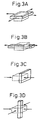
- Fig. 3A is a schematic illustration showing a model of the biaxial tension in Example 1.
- Fig. 3B is a schematic illustration showing a model of the uniaxial tension in Example 1.
- Fig. 3C is a schematic illustration showing a model of the uniaxial compression in Example 1.
- Fig. 3D is a schematic illustration showing a model of the biaxial compression in Example 1.
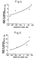
- Fig. 4 is a schematic illustration showing a relation between the hydrostatic pressure stress of SUS301 and the amount of generation of stress induced-martensite.
- Fig. 5 is a schematic illustration showing a relation between the hydrostatic pressure stress of SUS304 and the amount of generation of stress induced-martensite.
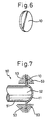
- Fig. 6 is a perspective view of the material in Example 3.
- Fig. 7 is a schematic illustration showing a process of bulging in Example 3.
- Fig. 8 is a schematic illustration showing an initial condition of spinning in Example 3.
- Fig. 9 is a schematic illustration showing a final condition of spinning in Example 3.
- Fig. 10 is a schematic illustration showing a state of solution heat treatment in Example 3.
- Fig. 11 is a schematic illustration showing a composite magnetic member in Example 3.
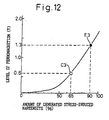
- Fig. 12 is a schematic illustration showing a relation between the amount of generation of stress induced-martensite and the level of ferromagnetism .
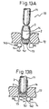
- Fig. 13A is a schematic illustration showing a state in which an intermediately formed body is set in a device in Example 1.
- Fig. 13B is a schematic illustration showing a state in which a non-magnetic portion of the intermediately formed body is expanded.
- Fig. 14A is a schematic illustration showing a state in which an intermediately formed body is subjected to ironing in Example 1.
- Fig. 14B is a schematic illustration showing a state in which ironing has been completed in Example 1.
- Fig. 14C is a schematic illustration showing a composite magnetic member obtained by ironing in Example 1.
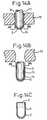
- Figs. 15A to 15F are schematic illustrations showing a procedure of producing an intermediately formed body in Example 1.
- Fig. 16 is a schematic illustration showing a state in which a non-magnetic portion is formed in an intermediately formed body in Example 1.
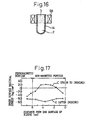
- Fig. 17 is a schematic illustration showing a state of residual stress before and after ironing in Example 1.
- Fig. 18 is a cross-sectional view of an electromagnetic valve in Example 3.
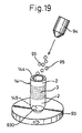
- Fig. 19 is a schematic illustration showing a process of shot peening in Example 4.
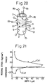
- Fig. 20 is a schematic illustration showing a state in which shot particles are colliding with an intermediately formed body in Example 4.
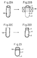
- Fig. 21 is a schematic illustration showing a change in the residual stress in an intermediately formed body in Example 4.
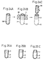
- Figs. 22A and 22B are schematic illustrations showing a method of forming a non-magnetic portion of a composite magnetic member in the conventional example.
- Figs. 22C and 22D are schematic illustrations showing a change in the shape of a non-magnetic portion when it is formed.
- Fig. 23 is a schematic illustration showing a state of generation of stress corrosion in the conventional example.
- Figs. 24A to 24C are schematic illustrations showing a method of correcting a shape in the conventional example.
- Fig. 25A is a schematic illustration showing a state in which a non-magnetic portion has been excessively expanded as a result of correction of the shape in the conventional example.
- Fig. 25B is a schematic illustration showing a state in which a non-magnetic portion has been appropriately expanded as a result of correction of the shape in the conventional example.
- Fig. 25C is a schematic illustration showing a state in which a non-magnetic portion has not been expanded sufficiently as a result of correction of the shape in the conventional example.
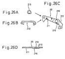
- Figs. 26A to 26D are views showing a shape of the conventional yoke and also showing a process of producing the yoke.
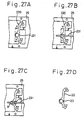
- Figs. 27A to 27D are views showing a shape of the conventional yoke and also showing another process of producing the yoke.
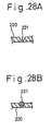
- Fig. 28A is a cross-sectional view taken on line X - X in Fig. 27A.
- Fig. 28B is a cross-sectional view taken on line Y - Y in Fig. 27B.
- Figs. 29A to 29C are views showing a flow of the method of production in Example 8.
- Fig. 30 is a plan view of a steel member (yoke) in Example 8.
- Fig. 31 is a plan view of another steel member (rotor) in Example 8.
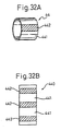
- Fig. 32A is a plan view of a steel member (rotor) in Example 9.
- Fig. 32B is a development view of the steel member (rotor) shown in Fig. 32A.
- Example 1 Conventional method
- material made of austenite stainless steel is subjected to cold working in a temperature range not lower than the point Ms and not higher than the point Md, so that the austenite phase can be transformed into the stress induced-martensite phase.
- cold working is a biaxial tensing.
- Figs. 3A to 3D four types of methods were investigated including a biaxial tensing (shown in Fig. 3A), uniaxial tensing (shown in Fig. 3B), uniaxial compression (shown in Fig. 3C), and biaxial compression (shown in Fig. 3D).
- Test pieces of SUS301 were made of a sheet, the thickness of which was 1 mm, and test pieces of SUS304 were made of an ingot.
- the test pieces of SUS301 were made as follows. Two sheets of SUS301 were put upon each other and joined by the thermal diffusion method. Then the joined sheets were machined into a block member and subjected to finishing heat treatment. In this way, test pieces for uniaxial compression and those for biaxial compression were made.
- test piece the shape of which was machined into a predetermined shape, was subjected to solution heat treatment while it was kept for the time of 7.2ks under the condition that the degree of vacuum was 10 -3 Pa and the temperature was 1373K.
- solution heat treatment was conducted when the test pieces were held for the total time of 5.8ks in total.
- the thirteenth test piece stipulated by JIS Z2201 was used.
- the size of the test piece is described as follows. Width W is 10 mm, measuring points distance L is 40 mm, length of the parallel portion P is 60 mm, radius R of curvature of the shoulder portion is 10 mm, and thickness T is 1 mm.
- a disk-shaped bulging test piece (?) was used, wherein the diameter of the test piece was 90 mm and the thickness of the test piece was 1 mm.
- the test piece was subjected to a bulging test (?) .
- the determination of the martensite phase was measured by the Fisher Ferritescope. Further, polycrystal X-ray diffraction was conducted in order to make investigation into the crystal structure of austenite and martensite and check the value of determination of the martensite phase. In this case, Co-K ⁇ rays were used as the source of X-rays.
- Figs. 1 and 2 the horizontal axis expresses an equivalent strain
- the vertical axis expresses an amount (%) of the generation of stress induced-martensite.
- the biaxial tensing is represented by E11 and E21
- the uniaxial tensing is represented by C12 and C22
- the uniaxial compression was represented by C13 and C23
- the biaxial compression was represented by C14 and C24.
- Fig. 1 shows the result of the test conducted on SUS301
- Fig. 2 shows the result of the test conducted on SUS304.
- stress induced-martensite was generated at a ratio higher than that of the case of other working. It can be understood that stress induced-martensite tends to be generated in the order of biaxial tensing, uniaxial tensing, uniaxial compression, and biaxial compression in this example.
- Example 1 In order to confirm the result of evaluation of Example 1, an influence of hydrostatic stress with respect to the generation of stress induced-martensite was investigated.
- Example 1 a relation between the hydrostatic stress and the ratio of the generation of stress induced-martensite was found when the equivalent strain was approximately 0.1 in the four types of tests of uniaxial tension, biaxial tension, uniaxial compression, and biaxial compression.
- Fig. 4 shows a result of the test conducted on SUS301
- Fig. 5 shows a result of the test conducted on SUS304.
- Figs. 4 and 5 marks showing the results of the test are arranged in the order of biaxial tension, uniaxial tension, uniaxial compression and biaxial compression from the side on which the hydrostatic stress is high. As can be seen in Figs. 4 and 5, a ratio of the generation of stress induced-martensite is increased in the order of biaxial tension, uniaxial tension, uniaxial compression and biaxial compression.
- the composite magnetic member 1 to be produced in this example is cylindrical.
- a non-magnetic portion 3 In an upper half portion of the composite magnetic member 1, there is provided a non-magnetic portion 3, and in a lower half portion, there is provided a ferromagnetic portion 2.
- a disk-shaped material 10 illustrated in Fig. 6 is used. This disk-shaped material 10 is made of austenite stainless steel.
- the material 10 is subjected to cold working in the temperature range not lower than the point Ms and not higher than the point Md. Due to the above cold working, the non-magnetic austenite phase is transformed into the ferromagnetic martensite phase by the stress induced-transformation, so that the ferromagnetic portion 2 can be formed.
- a portion of the ferromagnetic portion 2 is subjected to solution heat treatment, and the non-magnetic portion 3 of the austenite phase can be formed.
- the material 10 is prepared. As illustrated in Fig. 6, the material 10 is a disk-shaped blank material, which is made of austenite stainless steel, the chemical composition of which is shown on Table 2. The entire material 10 is made of the non-magnetic austenite phase. C Si Mn P S Cr Ni Fe Chemical Composition 0.026 0.20 0.38 0.007 0.004 17.76 8.28 Bal.
- cold working is conducted on the non-magnetic material 10 to cause the stress induced-transformation.
- This cold working is a combination of bulging, which is the biaxial tension working illustrated in Fig. 7, with spinning which is the uniaxial compression working illustrated in Figs. 8 and 9.
- a bulging device 50 composed of a punch 51 having a spherical portion 52, the radius of which is 25 mm, and also composed of a cramp 53 to hold the material 10.
- the material 10 is bulged by a distance of 16 mm, so that the material 10 can be formed into an intermediately formed body 11.
- the equivalent strain is 0.25.
- the intermediately formed body 11 is subjected to spinning of uniaxial compression by which the degree of working can be enhanced.
- spinning is conducted by a spinning device 60 composed of a forming die 61 rotated together with the intermediately formed body 11 and a moving roller 62.
- a spinning device 60 composed of a forming die 61 rotated together with the intermediately formed body 11 and a moving roller 62.
- the moving roller 62 is gradually moved from the fore end portion 111 of the intermediately formed body, spinning is conducted on the intermediately formed body.
- An amount of the equivalent strain in the processes of bulging and spinning is 0.5.
- the material 10 is subjected to bulging which is a biaxial tension working and also subjected to spinning which is a uniaxial compression working. Due to the foregoing, the material 10 is formed into a second intermediately formed body 12 having a ferromagnetic portion 3 in which martensite induced by working is entirely generated.
- the fore end portion 121 of the second intermediately formed body 12 is cut off, and the upper half is subjected to solution heat treatment conducted by induction heating of a high frequency induction coil 7 for a period of time not more than 10 seconds.
- An amount of the generation of stress induced-martensite reached 90% in the ferromagnetic portion 2, and the magnetic flux density B 4000 reached 1.3T.
- the biaxial tension working was not conducted, but only spinning of the uniaxial compression working was conducted to give an equivalent strain 0.5 which was the same as that of this example.
- the member to be compared was made. Portions of the member except for the portion subjected to cold working were made in the same manner as that of the member made by the method of producing the composite magnetic member of this example.
- the same measurement as that described above was conducted on the ferromagnetic portion of the thus obtained member to be compared. As a result of the measurement, the ratio of the generation of stress induced-martensite was approximately 65%, and the magnetic flux density B 4000 was 0.6T.
- Fig. 12 The above relation is shown in Fig. 12.
- the horizontal axis represents an amount (%) of the generation of martensite induced by working, and the vertical axis represents a ferromagnetism level (magnetic flux density B 4000 ).
- the ferromagnetism level of the ferromagnetic portion in this example is expressed by E3, and the ferromagnetism level of the member to be compared is expressed by C3.
- the method of this example is very effective to enhance the magnetic characteristic of the ferromagnetic portion.
- the specific magnetic permeability ⁇ in the nonmagnetic portion 3 was 1.00 to 1.05, that is, the magnetic characteristic of the non-magnetic portion 3 was very excellent.
- an intermediately formed body 14 the section of which is formed into a U-shape, is made.
- This intermediately formed body 14 includes a ferromagnetic portion 2 and a non-magnetic portion 3 which is contracted inward.
- a punch 71 is inserted into the intermediately fonmed body 14, so that the non-magnetic portion 3 is expanded.
- the intermediately formed body 14 is subjected to ironing so that the residual tensile stress can be changed into a residual compressive stress in the non-magnetic portion 3. Due to the foregoing, the composite magnetic member 1 can be obtained as illustrated in Fig. 14C.
- the intermediately formed body 14 is made of an austenite alloy steel sheet 101 shown in Fig. 15A, the composition of which is specifically described as follows.
- C is not more than 0.6 weight %
- Cr is 12 to 19 weight %
- Ni is 6 to 12 weight %
- Mn is not more than 2 weight %
- Figs. 15A to 15D the above steel sheet 101 is subjected to deep drawing and formed into a body 104, the section of which is U-shaped as illustrated in Fig. 15D.
- this body is subjected to drawing with ironing by a plurality of times using a die 195.
- an entirely ferromagnetic U-shaped member 106 is obtained as illustrated in Fig. 15F.
- the inner diameter of the U-shaped member 106 is 7.05 mm, and the thickness is 0.86 mm.
- a portion of the U-shaped member 106 on the opening side is subjected to solution annealing with a high frequency induction heating device 98. Due to the foregoing, it is possible to obtain an intermediately formed body 14 in which the ferromagnetic portion 2 and the non-magnetic portion 3 are continuously arranged.
- the non-magnetic portion 3 of this intermediately formed body 14 is contracted inward by the influence of transformation of the phase.
- the minimum inner diameter of the non-magnetic portion 3 is 7.02 mm.
- the size of the ferromagnetic portion 2 is the same as that of the above U-shaped member 106.
- the device 5 to conduct expansion and ironing includes a punch 71 used for press-fitting and ironing, and a die 72 used for drawing with ironing.
- the outer diameter of the punch 71 is 7.08 mm, which is larger than the inner diameter of the main body by 0.03 mm.
- the inner diameter of the die 72 is 8.68 mm. Therefore, when the intermediately formed body 14 is subjected to ironing, an amount of ironing is set at 0.06 mm, that is, a ratio of ironing is set at about 7%.
- a cushion plate 73 to support the intermediately formed body 14 when the punch 71 is press-fitted into the intermediately formed body 14.
- This cushion plate 73 is supported by the back pressure of 500 kgf/cm 2 , so that the intermediately formed body 14 can be positively supported by this cushion plate 73 when the punch 71 is press-fitted.
- the cushion plate 73 is arranged in such a manner that it is located inside the die 72 only in the case of press-fitting, and withdrawn to a position where the cushion plate 73 can not interfere with the movement of the punch 71 in the case of ironing.
- knockout portions 74 On the delivery side of the die 72, there are provided a pair of knockout portions 74 to remove an intermediately formed body, which has already been subjected to ironing, from the punch 71. These knockout portions 74 are supported by springs 745 arranged outside of them in such a manner that the knockout portions 74 can be withdrawn.
- a tapered portion 741 on the side of the die 72.
- a right-angled engaging angle portion 742 which engages with the opening end portion of the intermediately formed body after the completion of drawing with ironing.
- the non-magnetic portion 3 of the intermediately formed body 14 is expanded and drawn with ironing by the above device 70 as follows. First, as illustrated in Fig. 13A, the intermediately formed body 14 is set at the center of the die 72 and made to come into contact with the cushion plate 73. Then, the punch 71 is made to advance. Since the intermediately formed body 14 is supported by the cushion plate 73 in this case, the punch 71 is press-fitted into the intermediately formed body 14.
- inside diameters of both the ferromagnetic portion 2 and the non-magnetic portion 3 of the intermediately formed body 14 are expanded to be the same value as that of the outer diameter of the punch 71.
- the cushion plate 73 is withdrawn and the punch 71 is further advanced.
- the intermediately formed body 14 is drawn with ironing by a ratio of about 7% while the knockout portions 74 are being drawn outside. Then, as illustrated in Fig. 14B, at the completion of ironing, the knockout portions 74 are advanced inward by the pushing forces of the springs 745.
- the horizontal axis represents a distance from the end portion of the opening of the composite magnetic member, and the vertical axis represents a residual stress on the inside of the composite magnetic member.
- a state before ironing is represented by reference mark C, and a state after ironing is represented by reference mark E.
- the magnetic characteristic of the obtained composite magnetic member was evaluated. As a result of evaluation, the magnetic characteristic was very excellent as follows.
- the ferromagnetic level in the ferromagnetic portion 2 was not lower than 0.3T, and the non-magnetic level in the non-magnetic portion 3 was that the specific magnetic permeability ⁇ was not higher than 1.2.
- the thus obtained composite magnetic member 1 was subjected to the stress corrosion cracking test.
- the testing method is described below. After test pieces had been dipped in the boiling liquid of MgCl 2 for 120 minutes, they were observed to check the occurrence of cracks. As a result of the test, no cracks were found, that is, the anti-stress corrosion cracking property was very high.
- the intermediately formed body was made in the same manner as that of Example 4, and then a ratio of ironing was variously changed in the process of ironing, so that an influence of the ratio of ironing was investigated.
- Concerning the intermediately formed body the following two types of intermediately formed bodies were prepared. One was an intermediately formed body, the composition of material (material E1) of which was the same as that of Example 4. The other was an intermediately formed body, in the composition of material (material E2) of which, the Hirayama's Equivalent was changed from 20% to 21%. Other points are the same as those of Example 4.
- the specific magnetic permeability ⁇ in the non-magnetic portion 3 was measured, and the magnetic characteristic was evaluated by this specific magnetic permeability.
- the above evaluation was made at the two atmospheric temperatures of 22°C and 40°C.
- the characteristic of the ferromagnetic portion from the theoretical viewpoint, there was no possibility that the characteristic of the ferromagnetic portion was deteriorated by the above working, which was confirmed in an experiment made by the inventors.
- the residual stress was measured in the boundary between the non-magnetic portion 3 and the ferromagnetic portion 2 of each composite magnetic member. This measurement was made on the inner surface of each composite magnetic member. The result of measurement is shown on Table 5. As can be seen on the table, the residual tensile stress was changed into the residual compressive stress in any material and condition, that is, it was possible to provide a very good state.
- each composite magnetic member was subjected to the stress corrosion cracking test.
- the test conditions were the same as those of Example 4.
- the test was made at the two atmospheric temperatures of 22°C and 40°C.
- the section of the intermediately formed hollow body was formed into a U-shape, and also the section of the thus obtained composite magnetic hollow body was formed into a U-shape.
- the shape is not limited to the specific example, for example, when the shape is hollow and there is provided no bottom, it is possible to obtain the same effect.
- the composite magnetic member made by the method of Example 4 was applied to a sleeve 9 which was one of the parts of the electromagnetic valve 8.
- This specific example will be explained as follows.
- This electromagnetic valve 8 is commonly used in an automobile for the purpose of controlling the communication of a hydraulic passage.
- the electromagnetic valve 6 is controlled in such a manner that a communicating condition of the hydraulic passage composed of an inlet 852 and an outlet 850 formed in the ferromagnetic stator 83 is opened and closed by a valve seat 856 having a communicating hole 854 and also by a ball 86 coming into contact with the valve seat 856.
- the ball 86 is attached to a fore end portion of the shaft 85 slidably arranged in the stator 83.
- This shaft 85 is connected to a plunger 84.
- a sleeve 9 On the other hand, on the fore end side of the stator 83, there is provided a sleeve 9, the section of which is formed into a U-shape.
- This sleeve 9 is a composite magnetic member.
- a plunger 84 is slidably arranged.
- This plunger 84 can be moved by a distance D, which is a moving space D formed between the stator 83 and the plunger 84 illustrated in Fig. 18.
- This moving space D can be maintained by a pushing force of the spring 89 arranged at the lower end of the shaft 85.
- a coil 81 which is arranged coaxially to the sleeve 9. Further outside the coil 81, there is provided a ferromagnetic yoke 80 which covers the coil 81. This yoke 80 is connected to both the sleeve 8 and the stator 83.
- the sleeve 8 is composed of a composite magnetic member.
- the main body located on the bottom side is a ferromagnetic portion 92, and the opening end side is a non-magnetic portion 93.
- the non-magnetic portion 93 is located in such a manner that the non-magnetic portion 93 covers the moving space D.
- the above coil 81 in the case of closing the hydraulic circuit, the above coil 81 is energized with electric current, so that it can be excited. Due to the foregoing, as illustrated in Fig. 18, there is formed a magnetic circuit L composed of the yoke 80 which is a ferromagnetic body, the ferromagnetic portion 92 of the sleeve 9, the plunger 84, the stator 83 and the yoke 80.
- an attraction force is generated between the plunger 84 and the stator 83 which are ferromagnetic bodies, so that the plunger 84 and the shaft 85 are moved while resisting a pushing force generated by the spring 89. Due to the foregoing, the ball 86 attached to the fore end of the shaft 85 comes into contact with the valve seat 856, and the hydraulic circuit is shut off.
- the magnetic characteristics of both the ferromagnetic portion 92 and the non-magnetic portion 93 are very important factors to determine the performance of the electromagnetic valve 8.
- the electromagnetic valve 8 is highly durable.
- One of the characteristics to determine the durability is the stress corrosion cracking resistance property.
- the sleeve 9 of the electromagnetic valve 8 of this example was produced by the method described in Example 4. Therefore, while the performance of the ferromagnetic portion and the non-magnetic portion is maintained high, the stress corrosion cracking resistance property can be greatly enhanced. Therefore; the performance of the electromagnetic valve 8 into which the above sleeve 9 is incorporated is high, and it is highly durable.
- both the opening end portion 144 and the bottom portion 145 are formed into ferromagnetic portions 2, and a non-magnetic portion 3 is provided between these ferromagnetic portions.
- shot particles 95 are shot out from a nozzle 94 and made to collide with the inside and the outside of the intermediately formed body 14.
- particles of #300 made of SUS304 were used as the shot particles 95.
- air pressure used for shooting the shot particles 95 was set at 0.2 to 0.5MPa.
- the processing time of peening was set at 5 to 30 seconds.
- Fig. 20 is a view showing a state of collision of the shot particles 95 against the intermediately formed body 14.
- the shot particles 95 are made to substantially uniformly collide with the inside and the outside of the intermediately formed body 14. Therefore, the shot particles 95 are made to collide with a portion where the residual tensile stress is generated.
- the shot particles 95 may be made to collide with only a portion where the residual tensile stress is generated, however, in this example, the shot particles 95 were made to uniformly collide with the above portion where the residual tensile stress is generated and also its peripheral portion.
- the intermediately formed body 14 is substantially uniformly given a compressive force. Therefore, in the portion where the residual tensile stress is given, the residual tensile stress is gradually reduced. Due to the foregoing, after the completion of shot peening, the residual tensile stress in the intermediately formed body 14 is greatly reduced, so that the stress corrosion cracking resistance property can be greatly enhanced.
- the residual stress in the intermediately formed body 14 was measured before and after the processing of shot peening.
- the measuring point is located on the inner circumferential surface side of the portion indicated by mark S in Fig. 20.
- the measurement was conducted in the direction of thickness of the intermediately formed body 14. That is, the measurement was conducted from the inner circumferential surface to a position, the depth of which was approximately 120 ⁇ m from the inner circumferential surface in the direction of thickness.
- Fig. 21 The result of measurement is shown in Fig. 21.
- the horizontal axis represents a depth in the thickness direction
- the vertical axis represents an intensity of the residual stress.
- the positive side represents a tensile stress
- the negative side represents a compressive stress.
- a state before shot peening is expressed by mark E41 (mark %)
- a state after shot peening is expressed by mark E42 (mark ).
- the processing of shot peening which is a process to remove a residual stress, is an effective means for enhancing the stress corrosion cracking resistance property of a composite magnetic member.
- a yoke incorporated into a motor of an electronic clock is formed into a shape shown in Figs. 26A to 26D.
- the yoke 20 is composed of a right ferromagnetic portion 212, a left ferromagnetic portion 211 and a non-magnetic portion 215 to magnetically separate (insulate) both the ferromagnetic portions 211, 212.
- FIG. 26A to 26C there are provided a ferromagnetic member 210 and a non-magnetic member 215, which are joined to each other by means of laser beam welding. After that, a slit 219 is formed in the ferromagnetic member 210, so that the ferromagnetic member 210 is divided into the right ferromagnetic portion 212 and the left ferromagnetic portion 211. In this way, the ferromagnetic portions 211, 212 are separated from each other by the slit 219 and the non-magnetic member 215. Therefore, it is possible to form different magnetic circuits by the ferromagnetic portions 211, 212.
- a non-magnetic wire 231 is placed in a groove 221 of a ferromagnetic member 220 formed by press forming, and both members 220, 231 are welded to each other and punched. That is, as illustrated in Fig. 27A, first, the ferromagnetic member 220 is formed by a progressive press die, and a groove 221 is formed at a position where a non-magnetic portion 23 is formed as illustrated in Fig. 27D. Then, as illustrated in Fig.
- the wire 231 and the ferromagnetic member 220 are welded with each other by means of laser beam welding at the position indicated by mark ... R.
- the member 22 is punched from the frame 25 and the wire 231.
- Japanese Unexamined Patent Publication No. 62-25863 discloses a method of forming a ferromagnetic portion and a non-magnetic portion in such a manner that magnetic particles are mixed in non-magnetic powder or liquid, and an intensity of distribution of magnetic field to be impressed is controlled so that the distribution of magnetic particles can be made to deviate.
- Japanese Unexamined Patent Publication No. 7-11397 discloses a method of producing a composite magnetic steel member composed of a ferromagnetic portion and a non-magnetic portion, the magnetic properties of which can be maintained even at an extremely low temperature of 40 degrees centigrade below freezing point.
- a portion to be made non-magnetic is locally heated so that the portion can be transformed into a non-magnetic portion.
- minute parts such as yokes and others to compose an electronic clock
- the reason is that the structure of the locally heated non-magnetic portion is transformed from martensite to austenite so that the volume is reduced. Accordingly, in the cases of producing minute parts, there is a possibility that the parts are deformed.
- the present invention is to provide a method of producing a steel member composed of a non-magnetic portion and a ferromagnetic portion, by which even a small steel member can be effectively mass-produced.
- this example shows a method of producing a steel member (yoke incorporated into a motor of an electronic clock) composed of a non-magnetic portion 41 and ferromagnetic portions 421, 422.
- This production method includes: a first process in which a non-magnetic long body 31 of the austenite structure is subjected to cold rolling by rollers 36, so that a ferromagnetic long body 32 of the martensite structure can be continuously formed as illustrated in Fig. 29A; a second process in which a portion 331 of the long body 32 corresponding to the non-magnetic portion 41 (shown in Fig. 29) is selectively annealed, so that a new long body 33 can be formed as illustrated in Fig. 29B; and a third process in which holes 341, 342 are formed in the partially annealed long body 33, and a steel member 40 of a predetermined shape is successively punched from the thus provided long body 34 as illustrated in Fig. 29C.
- annealing is conducted by irradiating laser beams 37. Due to the foregoing, a portion irradiated by the laser beams 37 can be made to be a non-magnetic body 332.
- a yoke 40 is separated by warm-punching conducted in the temperature range from 40°C to 600°C.
- the steel member (yoke) 40 to be produced in this example includes a band-shaped non-magnetic portion 41, and ferromagnetic portions 421, 422.
- a rotor hole 341 In the boundaries of the band-shaped non-magnetic portion 41 and the ferromagnetic portions 421, 422, there is formed a rotor hole 341, and in the ferromagnetic portions 421, 422, there are formed holes 342.
- the size of the yoke 40 is 9.9 ⁇ 3.7 mm, and the band width d of the non-magnetic portion 41 is 0.5 mm.
- the non-magnetic long body 31 made of austenite stainless steel SUS304 is cold-rolled as illustrated in Fig. 29A.
- the structure of the long body 31 is changed to martensite by the stress induced-martensite transformation, so that a ferromagnetic elongated body 32 can be obtained.
- the ferromagnetic stainless steel is subjected to solution heat treatment (ST treatment), so that the martensite structure is returned to the initial austenite structure, that is, the elongated body is made to be non-magnetic. and then it is subjected to processing.
- ST treatment solution heat treatment
- the solution heat treatment (ST treatment) is not conducted, but a portion of the ferromagnetic elongated body 32 is made to be non-magnetic. That is, a non-magnetic portion 332, the width of which is the same as "d" (shown in Fig. 30) of the width of the non-magnetic portion 41, is formed at a position corresponding to the non-magnetic portion 41 of the yoke 40 by the following process.
- this processing is performed as follows. While the long body 32 is continuously moved, a region of the width "d" of the elongated body 32 is irradiated with laser beams 37 emitted from the CO 2 laser beam source 38. The structure of this region irradiated with the laser beams 37 is transformed from martensite to austenite, that is, only this region is made to be non-magnetic. In this way, a band-shaped non-magnetic portion 332 is continuously formed.
- the holes 341 and 342 are successively formed in the long body 33. Then, punching is conducted in accordance with the shape of the yoke 40.
- the method of high frequency induction heating may be applied to the annealing process to form the non-magnetic portion 332.
- a rotor 45 of the stepping motor the shape of which is shown in Fig. 31.
- reference numeral 451 represents a ferromagnetic portion
- reference numeral 452 represents a non-magnetic portion.
- a sheet member 440 illustrated in Fig. 32B is made.
- reference numeral 441 is a ferromagnetic portion
- reference numeral 442 is a non-magnetic portion.
- the sheet member 440 is bent, so that the rotor 44 illustrated in Fig. 31 can be formed.
Landscapes
- Chemical & Material Sciences (AREA)
- Engineering & Computer Science (AREA)
- Materials Engineering (AREA)
- Crystallography & Structural Chemistry (AREA)
- Mechanical Engineering (AREA)
- Physics & Mathematics (AREA)
- Metallurgy (AREA)
- Organic Chemistry (AREA)
- Thermal Sciences (AREA)
- Electromagnetism (AREA)
- Manufacturing & Machinery (AREA)
- Power Engineering (AREA)
- Heat Treatment Of Articles (AREA)
- Heat Treatment Of Steel (AREA)
- Hard Magnetic Materials (AREA)
Description
- The present invention relates to a method of producing a composite magnetic member made of a steel material.
- EP 629 711 A1 discloses a method for producing a composite magnetic member by forming an intermediately formed hollow body having a ferromagnetic portion and a non-magnetic portion. In EP 629 711 A1 it is disclosed that strain caused by plastic working can be relieved by annealing at or below 500 ° C. However, such an annealing is not effective in reducing residual tensile stress. Concerning residual stress, it is disclosed in EP 629 711 A1 that 10 % or more ironing after forming a ferromagnetic portion by drawing can change the stress such that cracking does not occur. As it is further disclosed, the stress can be changed into residual compression strain by 20 % or more ironing. According to EP 629 711 A1, the ironing is carried out prior to the non-magnetization of a portion of the magnetic member, because these measurements are for preventing cracks caused by peripheral stress due to the drawing.
- At present, austenite stainless steel is widely used in various fields of railway vehicles to kitchen utensils for domestic use. Therefore, great importance is attached to the mechanical property of austenite stainless steel. Concerning austenite stainless steel, the following are well known. When austenite stainless steel is subjected to cold working in a temperature range from the point Ms to the point Md, the martensite phase is generated from the austenite phase which is a mother phase, so that the stress induced-martensite transformation is caused. In this case, the point Ms is an upper limit temperature at which martensite is generated by the isothermal transformation, and the point Md is an upper limit temperature at which martensite is generated by the stress inducing transformation. In this case, the above austenite phase is an fcc phase (face centered cubic phase). On the other hand, almost all of the above stress induced-martensite phase is composed of an α' martensite phase of the bcc phase (body-centered cubic phase), and a very small amount of the ε' martensite phase of the hcp phase (hexagonal close-packed phase) is contained. The stress induced-martensite phase is defined as the aforementioned α' martensite phase in this specification, hereinafter.
- In the case of a stress inducing martensite transformation, in accordance with increase in an amount of stress induced-martensite, there is a possibility that hardness and brittleness are increased and the mechanical property is changed.
- However, as described above, the crystal structure of the austenite phase is different from that of the stress induced-martensite phase. Therefore, the austenite phase stainless steel is a non-magnetic member, and the stress induced-martensite phase stainless steel is a ferromagnetic member, that is, their magnetic properties are greatly different from each other.
- Accordingly, when austenite stainless steel is used for a magnetic member or a composite magnetic member described later, it is very effective to increase a ratio of stress induced-ferromagnetic martensite phase.
- On the other hand, according to the conventional producing method disclosed in Japanese Unexamined Patent Publication Nos. 7-11397 and 8-3643, it is impossible to increase the magnetic flux density B4000 to a high magnetic level not less than 0.8T (tesla), wherein the magnetic flux density B4000 is defined as a magnetic flux density in the case of applying a magnetic field with an intensity of 4000 A/m.
- The reason why it is impossible to increase the magnetic flax density B4000 to a high magnetic level not less than 0.8 T (tesla) is considered as follows. An amount of strain which can be given to the magnetic member or the composite magnetic member is restricted by the limit at break and the shape of the member. According to the conventional cold working method, even if the maximum strain is given to the magnetic member or the composite magnetic member, a ratio of the generated stress induced-martensite is still low.
- For the above reasons, there is a demand for developing a method of positively generating a large amount of stress induced-martensite, that is, there is a demand for developing a method of increasing an amount of the generation of stress induced-martensite with respect to an amount of the strain given to the magnetic member or the composite magnetic member.
- Concerning the basic investigation with respect to the method of stress inducing transformation, for example, "Transformation Induced by Working of SUS304 in Various Stress Conditions" was reported in the Spring Lecture Meeting of Plastic Working held in 1995. However, even according to the above investigations, it was impossible to develop the method of generating stress induced-martensite at a high ratio.
- In order to solve the above problems, it is a first object of the present invention to provide a method of stress inducing transformation by which stress induced-martensite can be generated in austenite stainless steel at a high ratio of generation, and to provide a method of producing a magnetic member or composite magnetic member, the ferromagnetic property of which is high.
- Further, for example, in a device such as an electromagnetic valve having a magnetic circuit, it is necessary to provide parts in which ferromagnetic and non-magnetic portions are integrated with each other. In order to produce such parts having both ferromagnetic and non-magnetic portions, for example, ferromagnetic and non-magnetic parts are separately produced, and then they are integrally connected with each other. However, according to the above production method, the durability of the connecting portion of the ferromagnetic part with the non-magnetic part is not so high, and further the production cost increases.
- On the other hand, Japanese Unexamined Patent Publication No. 8-3643 discloses a composite magnetic member and a production method thereof in which ferromagnetic and non-magnetic portions are contiguously formed without having a connecting portion.
- As shown in an embodiment described later, the above composite magnetic member can be provided as follows. Austenite alloy steel of a specific composition is used. This austenite alloy steel is subjected to cold working in a predetermined condition so as to generate stress induced-martensite. In this way, the austenite alloy steel is made to be ferromagnetic. After that, desired portions are subjected to solution heat treatment, so that these portions can be made to be non-magnetic.
- For example, as shown in Figs. 22A to 22D, there is provided a composite
magnetic member 6 in which the main body is composed of aferromagnetic portion 2 and the opening side portion is composed of anon-magnetic portion 3. In order to produce the above compositemagnetic member 6, first, as shown in Figs. 15A to 15F explained later, aplate 101 of austenite alloy steel is subjected to pressing by a plurality of times. In this way, the austenitealloy steel plate 101 is formed into a U-shapedmember 106 by cold working. Due to the above cold working, stress induced-martensite is generated in the entire U-shapedmember 106. Therefore, the entire U-shapedmember 106 becomes ferromagnetic. Next, as shown in Figs. 22A and 22B, the opening side portion of the U-shapedmember 106 is subjected to solution annealing by a high frequencyinduction heating unit 98. Due to the above high frequency induction heating, the opening side portion of the U-shapedmember 106 is made to be austenite, that is, anon-magnetic portion 3. - The thus obtained composite
magnetic member 6 is excellent in the magnetic property. For example, the magnetic flux density B4000 (the magnetic flux density at H = 4000 A/m) of the ferromagnetic portion is not less than 0.3T, and the specific permeability of the non-magnetic portion µ is lower than 1.2. - However, the following problems may be encountered in the above conventional composite
magnetic member 6. - As shown in Fig. 23,
stress corrosion cracks 99 tend to occur in thenon-magnetic portion 3 close to the boundary between thenon-magnetic portion 3 and theferromagnetic portion 2. - The reason why
stress corrosion cracks 99 tend to occur is considered as follows. - As described above, the conventional composite
magnetic member 6 is composed of theferromagnetic portion 2 made of martensite and thenon-magnetic portion 3 made of austenite. The crystal structure of austenite and that of martensite are different from each other. Therefore, the density of austenite and that of martensite are different from each other. For the above reasons, the volume of martensite is larger than that of austenite by 3% when the weight of martensite is the same as that of austenite. - In the conventional composite
magnetic member 6, material of austenite is used. This material of austenite is transformed into martensite so as to form theferromagnetic portion 2. Then, a portion of theferromagnetic portion 2 made of martensite is returned to austenite, so that thenon-magnetic portion 3 can be formed. Therefore, as shown in Figs. 22C and 22D, only thenon-magnetic portion 3 is reduced in its volume by 3% compared with the volume of theferromagnetic portion 2. As a result, residual tensile stress is generated in a portion of thenon-magnetic portion 3 close to the boundary between thenon-magnetic portion 3 and theferromagnetic portion 2. It is considered that the generation of this residual tensile stress greatly deteriorates the stress corrosion cracking resistance property. - On the other hand, there is provided another method. As shown in Figs. 24A to 24C, after the completion of high frequency induction heating for making a portion of the composite
magnetic member 6 to be non-magnetic, apunch 96 is forced in the inside of the compositemagnetic member 6 so as to expand thenon-magnetic portion 3. In this way, thenon-magnetic portion 3 is plastically deformed, so that the above residual tensile stress can be removed. However, according to the above method, the following problems may be encountered. As shown in Figs. 25A to 25C, the size of expanding thenon-magnetic portion 3 becomes too large (shown in Fig. 25A) or too small (shown in Fig. 25C), that is, it is difficult to completely control the intensity of residual stress. In order to form thenon-magnetic portion 3 into the most appropriate shape as shown in Fig. 25B, it is necessary to control the outer diameter of thepunch 96 at a high level of accuracy of 0.01 mm, which is very difficult. - Another conventional method of removing the residual stress is a method of annealing a portion at which the residual tensile stress has been generated. However, in order to completely remove the residual tensile stress generated in the portion close to the boundary between the
non-magnetic portion 3 and theferromagnetic portion 2, it is necessary to anneal the entire composite magnetic member. When the entire composite magnetic member is annealed, the ferromagnetic portion is changed into a non-magnetic portion. Since the performance of the ferromagnetic portion must be maintained in the composite magnetic member, it is impossible to apply the above method. - In view of the above conventional problems, the second object of the present invention is to provide a composite magnetic member and a production method thereof by which the performance of the ferromagnetic portion and the non-magnetic portion can be maintained and it is possible to ensure a high stress corrosion cracking resistance property, as well as to provide an electromagnetic valve made of the above composite magnetic member.
- These objects are solved by the features of
claim 1. - It is preferable that the material is an austenite stainless steel, the composition of which is defined as follows. C is not more than 0.6 weight %, Cr is 12 to 19 weight %, Ni is 6 to 12 weight %, Mn is not more than 2 weight %, Mo is not more than 2 weight %, Nb is not more than 1 weight %, and the residual portion is composed of Fe and inevitable impurities, wherein Hirayama's Equivalent Heq = [Ni%] +1.05 [Mn%] + 0.65 [Cr%] + 0.35 [Si%] + 12.6 [C%] is 20 to 23%, and the nickel equivalent Nieq = [Ni%] + 30 [C%] + 0.5 [Mn%] is 9 to 12%, and the chromium equivalent Creq = [Cr%] + [Mo%] + 1.5 [Si%] + 0.5 [Nb%] is 16 to 19%.
- The reason why C is not more than 0.6% in the above composition of the material is described as follows. When the carbon content exceeds 0.6%, an amount of carbide is increased, and the working property is lowered. The reason why an amount of Cr is 12 to 19% and an amount of Ni is 6 to 12% is described as follows. When the amounts of these elements are decreased to values lower than the above lower limits, it is impossible to provide a sufficient non-magnetic property, the specific magnetic permeability µ of which is not higher than 1.2. On the other hand, when the amounts of these elements are increased to values higher than the above upper limits, it is impossible to provide a sufficient magnetic flux density B4000 higher than 0.3T. Further, when an amount of Mn exceeds 2%, the working performance is deteriorated.
- Mo and Nb are not necessarily added, however, Mo is effective to lower the point Ms, and Nb is effective to enhance the mechanical strength of the material. Therefore, according to an object, Mo or Nb may be added alone or together. In this case, when Mo exceeds 2% and Nb exceeds 1%, the working property is deteriorated. Therefore, it is preferable that the upper limit of Mo is 2% and the upper limit of Nb is 1%.
- As described above, when not only the composition of each element is restricted but also the elements are appropriately combined with each other, it is possible to surely provide a high magnetic property.
- When Hirayama's Equivalent Heq is smaller than 20%, the specific magnetic permeability µ exceeds 1.2, and a sufficient non-magnetic property is not obtained. On the other hand, when Hirayama's Equivalent Heq exceeds 23%, it is difficult for the magnetic flux density B4000 to exceeds 0.3T.
- For the same reason as that of Hirayama's Equivalent, the nickel equivalent Nieq is determined in a range from 9 to 12%, and the chromium equivalent Creq is determined in a range from 16 to 19%.
- In this case, the material usually contains Si by an amount not more than 2% and Al by an amount not more than 0.5%, wherein Si and Al are contained as deoxidation elements, and also the material usually contains other impurity elements. However, there is no possibility that these elements deteriorate the property of the composite magnetic member.
- Concerning the stainless steel produced in accordance with
claim 1 particularly the composite magnetic member, the shape may be formed into a cup shape, a cylindrical shape and a plate shape, etc., that is, it should be noted that the shape of the composite magnetic member is not particularly limited. - In order to accomplish the objects of the present invention, the present invention provides a method of producing a composite magnetic member comprising the steps of: forming an intermediately formed hollow body having a ferromagnetic portion and a non-magnetic portion, the non-magnetic portion contracting inward; and removing a residual tensile stress from the intermediately formed hollow body.
- The most remarkable point of this embodiment is that the embodiment includes a stress removing process in which a residual tensile stress is removed from the intermediately formed body. Conventionally, the intermediately formed body is used as a composite magnetic member as it is. However, according to the present invention, the stress removing process is added to the producing process of the composite magnetic member.
- It is possible to use various stress removing processes, however, it is necessary that at least the residual tensile stress is relieved or removed. A compressive stress may be remained as a result of conducting the stress removing process. As a specific stress removing process, it is preferable to adopt a process in which a mechanical stress is given from the outside, the detail of which will be described later. Due to the foregoing, it is possible to remove a residual tensile stress without deteriorating the magnetic property of the above composite magnetic member.
- Next, the mode of operation of this embodiment will be explained as follows.
- According to the method of producing the composite magnetic member of the embodiment of the present invention, the aforementioned intemediately formed body is subjected to the above stress removing process. In this stress removing process, the residual tensile stress is sufficiently relieved or removed from the intermediately formed body. Therefore, the occurrence of stress corrosion cracks caused by a residual tensile stress can be surely prevented.
- Consequently, according to this embodiment, it is possible to provide a method of producing a composite magnetic member having a high anti-stress corrosion property while the magnetic performance of the ferromagnetic portion and that of the non-magnetic portion are maintained.
- Concerning the hollow shape of the intermediately formed body, it is sufficient that the intermediately formed body has a hollow portion inside. Examples of the shape of the intermediately formed body are a cylindrical shape having no bottom; and other shapes having bottom portions.
- It is preferable that the cross-section of the intermediately formed hollow body is a U-shape. This shape is advantageous in that the intermediately formed hollow body can be easily subjected to clod drawing.
- The following embodiment is a specific means for removing stress.
- It is preferable to produce a composite magnetic member as follows. In the stress removing process, a punch is forced or press-fitted into the above intermediately formed body so that the non-magnetic portion is expanded. After that, under the condition that the punch is inserted, the intermediately formed body is subjected to drawing with ironing so that the residual tensile stress can be changed into a residual compressive stress in the non-magnetic portion.
- The most remarkable point of this embodiment is that the punch is forced into the intermediately formed body and then the intermediately formed body subjected to drawing with ironing as described above.
- As described later, the intermediately formed body is provided in such a manner that after austenite alloy steel has been subjected to cold drawing so that it can be formed into a hollow shape, a portion of the hollow shape is subjected to high frequency induction heating. In other words, the non-magnetic portion can be formed as follows. Stress-induced martensite is generated by conducting cold working on the intermediately formed body, so that the intermediately formed body is made to be ferromagnetic. After that, a portion of the intermediately formed body is subjected to solution annealing, so that the portion can be returned from martensite to austenite. In this way, the non-magnetic portion can be formed.
- In the intermediately formed body that has been made in the above manner, the non-magnetic portion is contracted inward as described above, and a residual tensile stress is generated in a portion close to the boundary between the non-magnetic portion and the ferromagnetic portion.
- When the outer diameter of the intermediately formed body is determined, it is necessary to give consideration to an amount of reduction of the thickness caused in the process of ironing.
- The punch used for expanding the non-magnetic portion and also used for conducting ironing is composed as follows. The outside diameter of the punch is the same as or slightly larger than the inside diameter of the main body of the intermediately formed body. Accordingly, when the punch is inserted into the intermediately formed body, it is closely contacted with the inner wall of the intermediately formed body.
- When the above ironing is conducted, an ironing ratio is determined so that a residual tensile stress can be changed into a residual compressive stress in the intermediately formed body. However, when an ironing ratio is increased, that is, when a ratio of working is increased, the specific magnetic permeability µ of the non-magnetic portion increases, and its property is deteriorated. For the above reasons, it is necessary to give consideration so that the ratio of working is not increased too high.
- Next, the mode of operation of this embodiment will be explained as follows.
- According to the method of producing the composite magnetic member of this embodiment, after the intermediately formed body has been made, the punch is forced or press-fitted into it. Due to the foregoing, the non-magnetic portion is expanded and closely contacted with the outer circumference of the punch. At the same time, the ferromagnetic portion is also closely contacted with the outer circumference of the punch. Therefore, even if the inner diameters of the ferromagnetic portion and the non-magnetic portion fluctuate a little, the inner diameter of the thus obtained composite magnetic member can be made to be the same.
- Next, while the punch is inserted into the intermediately formed body, it is subjected to ironing. Due to the above ironing, the thickness of the ferromagnetic portion can be made to be the same as the thickness of the non-magnetic portion. Therefore, the outer diameter of the ferromagnetic portion can be made to be the same as the outer diameter of the non-magnetic portion. When the above drawing with ironing is conducted, a ratio of drawing with ironing is determined so that a residual tensile stress can be changed into a residual compressive stress in the intermediately formed body and the property of the non-magnetic portion can not be deteriorated.
- Therefore, a residual tensile stress can be changed into a residual compressive stress in the composite magnetic member while the magnetic properties of the non-magnetic portion and the ferromagnetic portion are maintained in the intermediately formed body.
- For the above reasons, the stress corrosion-resistance property of the composite magnetic member can be sufficiently enhanced.
- Next, as described in the embodiment according to
claim 11, it is preferable that an ironing ratio is maintained at 2 to 9% in the process of ironing. Due to the foregoing, while the properties of the non-magnetic portion and the ferromagnetic portion are positively maintained in the intermediately formed body, a residual tensile stress can be changed into a residual compressive stress in the non-magnetic portion. - When the ratio of ironing is lower than 2%, there is a possibility that the residual tensile stress is not changed into the residual compressive stress. When the ratio of ironing exceeds 9%, there is a possibility that the specific magnetic permeability µ of the non-magnetic portion increases and its property is deteriorated. In this connection, the ratio of ironing is expressed by (t0 - t)/t0 × 100, wherein the thickness of material before conducting the ironing is t0, and the thickness of material after the completion of working is t.
- The following embodiment is another specific means for removing residual stress.
- In this process for removing residual stress, shot peening may be conducted on the inside or the outside of the above intermediately formed body where residual tensile stress has been generated. In this shot peening process, shot particles are made to collide with the inside or the outside of the above intermediately formed body.
- In this case, the residual tensile stress can be greatly reduced or removed by the very simple process of shot peening. Therefore, it is possible to greatly enhance the anti-stress corrosion property while the production cost is maintained low.
- According to the above method, shot particles are made to collide with a portion where tensile stress is given. Therefore, it is possible to reduce an intensity of residual tensile stress irrespective of the shape of the intermediately formed body.
- As described in the embodiment according to claim 13, when the above intermediately formed body having the ferromagnetic portion and the non-magnetic portion is produced, it is preferable that only a desired portion is heated so that the portion can be made to be non-magnetic after the material of the intermediately formed body has been subjected to cold drawing and made to be ferromagnetic. By the above method, it is possible to easily produce the above intermediately formed body, the magnetic property of which is high.
- Another embodiment of the composite magnetic member produced by the above method is described as follows.
- Another embodiment is a composite magnetic hollow member having a ferromagnetic portion and a non-magnetic portion wherein the composite magnetic hollow member is produced by the method described in
claim 1. - Since this composite magnetic member is produced by the production process in which residual stress is removed, its stress corrosion cracking resistance property is very high as described above.
- As described in the embodiment according to
claim 5, the cross-section of the hollow shape of the above composite magnetic member may be made to be a U-shape. In this case, it is preferable to compose this composite magnetic member in such a manner that the bottom side is formed into a ferromagnetic portion and the opening end side is formed into a non-magnetic portion. Due to the foregoing, the bottom side can be easily made to be ferromagnetic and the opening end side can be easily made to be non-magnetic. - It is preferable to adopt a separation method in which warm punching is conducted at a temperature in the range from 40°C to 600°C.
- When members are separated by means of punching, a minute amount of martensite (ferromagnetic portion) is generated in a small region of separation in which stress is acting. The thus generated ferromagnetic portion seldom affects the performance of a product, however, in the case of a small product, its performance is deteriorated. However, when warm punching is conducted at a temperature not lower than 40°C, the generation of martensite can be suppressed, and it is possible to produce a highly accurate product. However, when the temperature exceeds 600°C, the entire member becomes non-magnetic, and it is impossible to produce a member of steel composed of a non-magnetic portion and a ferromagnetic portion. For this reason, it is preferable to maintain the punching temperature in the range from 40°C to 600°C.
- Fig. 1 is a schematic illustration showing a relation between the equivalent strain and the amount of generation of stress induced-martensite of SUS301 with respect to various working methods in Example 1.
- Fig. 2 is a schematic illustration showing a relation between the equivalent strain and the amount of generation of stress induced-martensite of SUS304 with respect to various working methods in Example 1.
- Fig. 3A is a schematic illustration showing a model of the biaxial tension in Example 1.
- Fig. 3B is a schematic illustration showing a model of the uniaxial tension in Example 1.
- Fig. 3C is a schematic illustration showing a model of the uniaxial compression in Example 1.
- Fig. 3D is a schematic illustration showing a model of the biaxial compression in Example 1.
- Fig. 4 is a schematic illustration showing a relation between the hydrostatic pressure stress of SUS301 and the amount of generation of stress induced-martensite.
- Fig. 5 is a schematic illustration showing a relation between the hydrostatic pressure stress of SUS304 and the amount of generation of stress induced-martensite.
- Fig. 6 is a perspective view of the material in Example 3.
- Fig. 7 is a schematic illustration showing a process of bulging in Example 3.
- Fig. 8 is a schematic illustration showing an initial condition of spinning in Example 3.
- Fig. 9 is a schematic illustration showing a final condition of spinning in Example 3.
- Fig. 10 is a schematic illustration showing a state of solution heat treatment in Example 3.
- Fig. 11 is a schematic illustration showing a composite magnetic member in Example 3.
- Fig. 12 is a schematic illustration showing a relation between the amount of generation of stress induced-martensite and the level of ferromagnetism .
- Fig. 13A is a schematic illustration showing a state in which an intermediately formed body is set in a device in Example 1.
- Fig. 13B is a schematic illustration showing a state in which a non-magnetic portion of the intermediately formed body is expanded.
- Fig. 14A is a schematic illustration showing a state in which an intermediately formed body is subjected to ironing in Example 1.
- Fig. 14B is a schematic illustration showing a state in which ironing has been completed in Example 1.
- Fig. 14C is a schematic illustration showing a composite magnetic member obtained by ironing in Example 1.
- Figs. 15A to 15F are schematic illustrations showing a procedure of producing an intermediately formed body in Example 1.
- Fig. 16 is a schematic illustration showing a state in which a non-magnetic portion is formed in an intermediately formed body in Example 1.
- Fig. 17 is a schematic illustration showing a state of residual stress before and after ironing in Example 1.
- Fig. 18 is a cross-sectional view of an electromagnetic valve in Example 3.
- Fig. 19 is a schematic illustration showing a process of shot peening in Example 4.
- Fig. 20 is a schematic illustration showing a state in which shot particles are colliding with an intermediately formed body in Example 4.
- Fig. 21 is a schematic illustration showing a change in the residual stress in an intermediately formed body in Example 4.
- Figs. 22A and 22B are schematic illustrations showing a method of forming a non-magnetic portion of a composite magnetic member in the conventional example.
- Figs. 22C and 22D are schematic illustrations showing a change in the shape of a non-magnetic portion when it is formed.
- Fig. 23 is a schematic illustration showing a state of generation of stress corrosion in the conventional example.
- Figs. 24A to 24C are schematic illustrations showing a method of correcting a shape in the conventional example.
- Fig. 25A is a schematic illustration showing a state in which a non-magnetic portion has been excessively expanded as a result of correction of the shape in the conventional example.
- Fig. 25B is a schematic illustration showing a state in which a non-magnetic portion has been appropriately expanded as a result of correction of the shape in the conventional example.
- Fig. 25C is a schematic illustration showing a state in which a non-magnetic portion has not been expanded sufficiently as a result of correction of the shape in the conventional example.
- Figs. 26A to 26D are views showing a shape of the conventional yoke and also showing a process of producing the yoke.
- Figs. 27A to 27D are views showing a shape of the conventional yoke and also showing another process of producing the yoke.
- Fig. 28A is a cross-sectional view taken on line X - X in Fig. 27A.
- Fig. 28B is a cross-sectional view taken on line Y - Y in Fig. 27B.
- Figs. 29A to 29C are views showing a flow of the method of production in Example 8.
- Fig. 30 is a plan view of a steel member (yoke) in Example 8.
- Fig. 31 is a plan view of another steel member (rotor) in Example 8.
- Fig. 32A is a plan view of a steel member (rotor) in Example 9.
- Fig. 32B is a development view of the steel member (rotor) shown in Fig. 32A.
- Referring to Figs. 1, 2 and 3A to 3D, there is explained a method of stress inducing transformation of austenite stainless steel.
- According to the method of stress inducing transformation of austenite stainless steel of this example, material made of austenite stainless steel is subjected to cold working in a temperature range not lower than the point Ms and not higher than the point Md, so that the austenite phase can be transformed into the stress induced-martensite phase. In this example, cold working is a biaxial tensing.
- Two types of materials were prepared. Thus prepared materials were subjected to cold working in various ways, and amounts of the generated stress induced-martensite were measured so as to make investigation into the effect of cold working.
- Concerning the method of cold working, as the models are shown in Figs. 3A to 3D, four types of methods were investigated including a biaxial tensing (shown in Fig. 3A), uniaxial tensing (shown in Fig. 3B), uniaxial compression (shown in Fig. 3C), and biaxial compression (shown in Fig. 3D).
- In this connection, two types of materials of SUS301 and SUS304 were prepared. The respective chemical compositions are shown on Table 1.
- Test pieces of SUS301 were made of a sheet, the thickness of which was 1 mm, and test pieces of SUS304 were made of an ingot. In this connection, the test pieces of SUS301 were made as follows. Two sheets of SUS301 were put upon each other and joined by the thermal diffusion method. Then the joined sheets were machined into a block member and subjected to finishing heat treatment. In this way, test pieces for uniaxial compression and those for biaxial compression were made.
- Each test piece, the shape of which was machined into a predetermined shape, was subjected to solution heat treatment while it was kept for the time of 7.2ks under the condition that the degree of vacuum was 10-3 Pa and the temperature was 1373K. However, concerning the test pieces for uniaxial and biaxial compressions, for the reasons of joining and finishing, the solution heat treatment was conducted when the test pieces were held for the total time of 5.8ks in total.
- As a result, with respect to all test pieces, the crystal structure was adjusted to the crystal
grain size number 6. It was possible to provide test pieces in which it was unnecessary to give consideration to the difference of grain sizes.
- Next, a method of test for conducting each cold working will be explained below.
- In the uniaxial tensile test, the thirteenth test piece stipulated by JIS Z2201 was used. The size of the test piece is described as follows. Width W is 10 mm, measuring points distance L is 40 mm, length of the parallel portion P is 60 mm, radius R of curvature of the shoulder portion is 10 mm, and thickness T is 1 mm. The test was made by the Instron Universal Tester. In the test, an equivalent strain ε = 0.445 was given to the test piece of SUS301, and an equivalent strain ε = 0.281 was given to the test piece of SUS304.
- In the uniaxial compression test, a cubic test piece, the length of one side of which was 15 mm, was used as a compression test piece. Using a hydraulic type compression tester, the compression test piece of SUS301 was given an equivalent strain ε = 1.000 at the maximum, and the compression test piece of SUS304 was given an equivalent strain ε = 0.910 at the maximum while lubrication was repeatedly conducted.
- In the biaxial tensing test, a disk-shaped bulging test piece (?) was used, wherein the diameter of the test piece was 90 mm and the thickness of the test piece was 1 mm. Using a deep drawing tester, the test piece was subjected to a bulging test (?). The test piece of SUS301 was given an equivalent strain ε = 0.204 at the maximum, and the test piece of SUS304 was given an equivalent strain ε = 0.163 at the maximum. In this way, the equal biaxial tensing test was made.
- In the biaxial compression test, the same cubic test piece as that of the uniaxial compression test, the length of one side of which was 15 mm, was used. This equal biaxial compression test was made by a biaxial compression tester in which a hydraulic compression tester and a device to give a horizontal load by a stepping motor were combined with each other. In this equal biaxial compression test, the test piece of SUS301 was given an equivalent strain ε = 0.157, and the test piece of SUS304 was given an equivalent strain ε = 0.176.
- All the tests described above were carried out at an atmospheric temperature of 300K at a strain speed of 10-3/s so that the temperature of the test piece could not be raised by the heat generated in the process of deformation. Due to the foregoing, the temperature of the test piece could be maintained in a temperature range not lower than the point Ms and not higher than the point Md while the test was being performed.
- The determination of the martensite phase was measured by the Fisher Ferritescope. Further, polycrystal X-ray diffraction was conducted in order to make investigation into the crystal structure of austenite and martensite and check the value of determination of the martensite phase. In this case, Co-Kα rays were used as the source of X-rays.
- The results of the tests are shown in Figs. 1 and 2.
- In both Figs. 1 and 2, the horizontal axis expresses an equivalent strain, and the vertical axis expresses an amount (%) of the generation of stress induced-martensite. In these drawings, the biaxial tensing is represented by E11 and E21, the uniaxial tensing is represented by C12 and C22, the uniaxial compression was represented by C13 and C23, and the biaxial compression was represented by C14 and C24. Fig. 1 shows the result of the test conducted on SUS301, and Fig. 2 shows the result of the test conducted on SUS304.
- As can be seen in Figs. 1 and 2, in the case of biaxial tensing working, stress induced-martensite was generated at a ratio higher than that of the case of other working. It can be understood that stress induced-martensite tends to be generated in the order of biaxial tensing, uniaxial tensing, uniaxial compression, and biaxial compression in this example.
- Due to the foregoing, the following can be understood. In any working method, a ratio of the generation of stress induced-martensite increases when an amount of strain increases. However, when a method is adopted, by which stress is strongly given to the material in a direction so that the volume of the material can increase, the ratio of the generation of stress induced-martensite can more increase.
- In this example, evaluation was made by Hirayama's Ni equivalent or Nobara's Md30(K) which are commonly used as a standard to indicate the stress induced-transformation According to the above evaluation, the transformation induced by working tends to occur in SUS301 more than SUS304. However, according to this example, the amount of generation of stress induced-martensite in the case of SUS304 is larger than that of stress induced-martensite in the case of SUS301. It is considered that the reason is a difference of the carbon (C) content between SUS301 and SUS304 (shown on Table 1). Since the carbon content of SUS301 is larger than that of SUS304, SUS301 requires a higher drive power for the transformation induced by working.
- In order to confirm the result of evaluation of Example 1, an influence of hydrostatic stress with respect to the generation of stress induced-martensite was investigated.
- In Example 1, a relation between the hydrostatic stress and the ratio of the generation of stress induced-martensite was found when the equivalent strain was approximately 0.1 in the four types of tests of uniaxial tension, biaxial tension, uniaxial compression, and biaxial compression. Fig. 4 shows a result of the test conducted on SUS301, and Fig. 5 shows a result of the test conducted on SUS304.
- In Figs. 4 and 5, marks showing the results of the test are arranged in the order of biaxial tension, uniaxial tension, uniaxial compression and biaxial compression from the side on which the hydrostatic stress is high. As can be seen in Figs. 4 and 5, a ratio of the generation of stress induced-martensite is increased in the order of biaxial tension, uniaxial tension, uniaxial compression and biaxial compression.
- According to this example, the following can be noted. When the hydrostatic pressure is high, the generation of stress induced-martensite tends to occur, and the working of biaxial tension is very advantageous for the stress induced-transformation.
- Next, referring to Figs. 6 to 12, a method of producing the composite magnetic member of the example will be explained below.
- As illustrated in Fig. 11, the composite
magnetic member 1 to be produced in this example is cylindrical. In an upper half portion of the compositemagnetic member 1, there is provided anon-magnetic portion 3, and in a lower half portion, there is provided aferromagnetic portion 2. When this compositemagnetic member 1 is produced, a disk-shapedmaterial 10 illustrated in Fig. 6 is used. This disk-shapedmaterial 10 is made of austenite stainless steel. - Then, as illustrated in Figs. 7 to 9, the
material 10 is subjected to cold working in the temperature range not lower than the point Ms and not higher than the point Md. Due to the above cold working, the non-magnetic austenite phase is transformed into the ferromagnetic martensite phase by the stress induced-transformation, so that theferromagnetic portion 2 can be formed. - Next, as illustrated in Fig. 10, a portion of the
ferromagnetic portion 2 is subjected to solution heat treatment, and thenon-magnetic portion 3 of the austenite phase can be formed. - Due to the foregoing, it is possible to produce a composite
magnetic member 1 continuously having theferromagnetic portion 2 and thenon-magnetic portion 3 as illustrated in Fig. 11. - Concerning the cold working of this example, after the biaxial tension working, the uniaxial or biaxial compression working is further conducted.
- This cold working will be described below in detail.
- First, the
material 10 is prepared. As illustrated in Fig. 6, thematerial 10 is a disk-shaped blank material, which is made of austenite stainless steel, the chemical composition of which is shown on Table 2. Theentire material 10 is made of the non-magnetic austenite phase.C Si Mn P S Cr Ni Fe Chemical Composition 0.026 0.20 0.38 0.007 0.004 17.76 8.28 Bal. - Next, as illustrated in Figs. 7 to 9, cold working is conducted on the
non-magnetic material 10 to cause the stress induced-transformation. This cold working is a combination of bulging, which is the biaxial tension working illustrated in Fig. 7, with spinning which is the uniaxial compression working illustrated in Figs. 8 and 9. - The cold working is specifically described as follows. As illustrated in Fig. 7, there is provided a bulging
device 50 composed of apunch 51 having aspherical portion 52, the radius of which is 25 mm, and also composed of acramp 53 to hold thematerial 10. Using this bulgingdevice 50, thematerial 10 is bulged by a distance of 16 mm, so that the material 10 can be formed into an intermediately formedbody 11. In this case, the equivalent strain is 0.25. - Then, cold working is further conducted on the material so as to increase the equivalent strain. As illustrated in Figs. 8 and 9, the intermediately formed
body 11 is subjected to spinning of uniaxial compression by which the degree of working can be enhanced. An outer circumferential portion of the intermediately formedbody 11, which has been held by thecramp 53 in the process of bulging, is previously cut off before spinning. - As illustrated in Figs. 8 and 9, spinning is conducted by a
spinning device 60 composed of a formingdie 61 rotated together with the intermediately formedbody 11 and a movingroller 62. When the movingroller 62 is gradually moved from thefore end portion 111 of the intermediately formed body, spinning is conducted on the intermediately formed body. An amount of the equivalent strain in the processes of bulging and spinning is 0.5. - As described above, the
material 10 is subjected to bulging which is a biaxial tension working and also subjected to spinning which is a uniaxial compression working. Due to the foregoing, thematerial 10 is formed into a second intermediately formedbody 12 having aferromagnetic portion 3 in which martensite induced by working is entirely generated. - Next, as illustrated in Fig. 10, the
fore end portion 121 of the second intermediately formedbody 12 is cut off, and the upper half is subjected to solution heat treatment conducted by induction heating of a high frequency induction coil 7 for a period of time not more than 10 seconds. - Due to the foregoing, as illustrated in Fig. 11, it is possible to obtain a composite
magnetic member 1, the upper half of which is anon-magnetic portion 3, and the lower half of which is aferromagnetic portion 2. - Next, in this example, in order to evaluate the magnetic characteristic of the obtained composite magnetic material, an amount of the generation of stress induced-martensite in the ferromagnetic portion was measured, and also magnetic flux density B4000 was measured. At the same time, the specific magnetic permeability of the
non-magnetic portion 3 was measured. - The method of measuring an amount of the generation of stress induced-martensite was the same as that of Example 1.
- The result of measurement will be explained below.
- An amount of the generation of stress induced-martensite reached 90% in the
ferromagnetic portion 2, and the magnetic flux density B4000 reached 1.3T. - For convenience of comparison, the biaxial tension working was not conducted, but only spinning of the uniaxial compression working was conducted to give an equivalent strain 0.5 which was the same as that of this example. In this way, the member to be compared was made. Portions of the member except for the portion subjected to cold working were made in the same manner as that of the member made by the method of producing the composite magnetic member of this example. The same measurement as that described above was conducted on the ferromagnetic portion of the thus obtained member to be compared. As a result of the measurement, the ratio of the generation of stress induced-martensite was approximately 65%, and the magnetic flux density B4000 was 0.6T.
- The above relation is shown in Fig. 12. In Fig. 12, the horizontal axis represents an amount (%) of the generation of martensite induced by working, and the vertical axis represents a ferromagnetism level (magnetic flux density B4000). The ferromagnetism level of the ferromagnetic portion in this example is expressed by E3, and the ferromagnetism level of the member to be compared is expressed by C3. As can be seen in Fig. 12, even if the cold working was conducted so that the same equivalent strain of 0.5 could be given, in the case of uniaxial compression working, the ratio of the generation of martensite induced by working was low, and the ferromagnetism level was also low, however, in the case where the biaxial tension working was conducted in this example, the ratio of the generation of martensite induced by working was enhanced and the ferromagnetism level was also enhanced.
- Due to the foregoing description, the method of this example is very effective to enhance the magnetic characteristic of the ferromagnetic portion.
- The specific magnetic permeability µ in the
nonmagnetic portion 3 was 1.00 to 1.05, that is, the magnetic characteristic of thenon-magnetic portion 3 was very excellent. - As described above, in this example, it is possible to easily produce a composite
magnetic member 1 having theferromagnetic portion 2, the ferromagnetic characteristic of which is excellent, and thenon-magnetic portion 3, wherein theferromagnetic portion 2 and thenon-magnetic portion 3 are continuously arranged in the compositemagnetic member 1. - Referring to Figs. 13A to 17, a method of producing the composite magnetic member of the example of the present invention will be explained below.
- According to the method of producing the composite magnetic member of this example, as illustrated in Figs. 13A and 13B, first, an intermediately formed
body 14, the section of which is formed into a U-shape, is made. This intermediately formedbody 14 includes aferromagnetic portion 2 and anon-magnetic portion 3 which is contracted inward. - Then, as illustrated in Figs. 13A and 13B, a
punch 71 is inserted into the intermediatelyfonmed body 14, so that thenon-magnetic portion 3 is expanded. After that, as illustrated in Figs. 14A and 14B, while thepunch 71 is inserted, the intermediately formedbody 14 is subjected to ironing so that the residual tensile stress can be changed into a residual compressive stress in thenon-magnetic portion 3. Due to the foregoing, the compositemagnetic member 1 can be obtained as illustrated in Fig. 14C. - The following are the detailed descriptions.
- The intermediately formed
body 14 is made of an austenitealloy steel sheet 101 shown in Fig. 15A, the composition of which is specifically described as follows. - C is not more than 0.6 weight %, Cr is 12 to 19 weight %, Ni is 6 to 12 weight %, Mn is not more than 2 weight %, and the residual portion is composed of Fe and inevitable impurities, wherein Hirayama's Equivalent Heq = [Ni%] + 1.05 [Mn%] + 0.65 [Cr%] + 0.35 [Si%] + 12.6 [C%] is 20 to 23%, and the nickel equivalent Nieq = [Ni%] + 30 [C%] + 0.5 [Mn%] is 9 to 12%, and the chromium equivalent Creq = [Cr%] + [Mo%] + 1.5 [Si%] + 0.5 [Nb%] is 16 to 19%.
- Then, as illustrated in Figs. 15A to 15D, the
above steel sheet 101 is subjected to deep drawing and formed into abody 104, the section of which is U-shaped as illustrated in Fig. 15D. Next, as illustrated in Fig. 15E, this body is subjected to drawing with ironing by a plurality of times using adie 195. In this way, an entirely ferromagneticU-shaped member 106 is obtained as illustrated in Fig. 15F. In this example, the inner diameter of theU-shaped member 106 is 7.05 mm, and the thickness is 0.86 mm. - Then, as illustrated in Fig. 16, a portion of the
U-shaped member 106 on the opening side is subjected to solution annealing with a high frequencyinduction heating device 98. Due to the foregoing, it is possible to obtain an intermediately formedbody 14 in which theferromagnetic portion 2 and thenon-magnetic portion 3 are continuously arranged. - As illustrated in Figs. 13A, 21C and 21D, the
non-magnetic portion 3 of this intermediately formedbody 14 is contracted inward by the influence of transformation of the phase. Specifically, the minimum inner diameter of thenon-magnetic portion 3 is 7.02 mm. In this case, the size of theferromagnetic portion 2 is the same as that of the aboveU-shaped member 106. - Next, there is provided an explanation for a
device 5 to conduct expansion and drawing with ironing on the abovenon-magnetic portion 3. As illustrated in Figs. 13A, 13B and 14A to 14C, thedevice 5 to conduct expansion and ironing includes apunch 71 used for press-fitting and ironing, and a die 72 used for drawing with ironing. The outer diameter of thepunch 71 is 7.08 mm, which is larger than the inner diameter of the main body by 0.03 mm. - The inner diameter of the die 72 is 8.68 mm. Therefore, when the intermediately formed
body 14 is subjected to ironing, an amount of ironing is set at 0.06 mm, that is, a ratio of ironing is set at about 7%. - As illustrated in Figs. 13A and 13B, inside the
die 72, there is provided acushion plate 73 to support the intermediately formedbody 14 when thepunch 71 is press-fitted into the intermediately formedbody 14. Thiscushion plate 73 is supported by the back pressure of 500 kgf/cm2, so that the intermediately formedbody 14 can be positively supported by thiscushion plate 73 when thepunch 71 is press-fitted. - The
cushion plate 73 is arranged in such a manner that it is located inside the die 72 only in the case of press-fitting, and withdrawn to a position where thecushion plate 73 can not interfere with the movement of thepunch 71 in the case of ironing. - On the delivery side of the die 72, there are provided a pair of
knockout portions 74 to remove an intermediately formed body, which has already been subjected to ironing, from thepunch 71. Theseknockout portions 74 are supported bysprings 745 arranged outside of them in such a manner that theknockout portions 74 can be withdrawn. - In order to withdraw the
knockout portion 74 to the outside easily in the case of ironing, there is provided a taperedportion 741 on the side of thedie 72. On the opposite side, there is provided a right-angledengaging angle portion 742 which engages with the opening end portion of the intermediately formed body after the completion of drawing with ironing. - The
non-magnetic portion 3 of the intermediately formedbody 14 is expanded and drawn with ironing by theabove device 70 as follows. First, as illustrated in Fig. 13A, the intermediately formedbody 14 is set at the center of thedie 72 and made to come into contact with thecushion plate 73. Then, thepunch 71 is made to advance. Since the intermediately formedbody 14 is supported by thecushion plate 73 in this case, thepunch 71 is press-fitted into the intermediately formedbody 14. - Due to the foregoing, inside diameters of both the
ferromagnetic portion 2 and thenon-magnetic portion 3 of the intermediately formedbody 14 are expanded to be the same value as that of the outer diameter of thepunch 71. - Next, the
cushion plate 73 is withdrawn and thepunch 71 is further advanced. - Due to the foregoing, as illustrated in Fig. 14A, the intermediately formed
body 14 is drawn with ironing by a ratio of about 7% while theknockout portions 74 are being drawn outside. Then, as illustrated in Fig. 14B, at the completion of ironing, theknockout portions 74 are advanced inward by the pushing forces of thesprings 745. - Therefore, when the
punch 71 is withdrawn in this condition, the engagingangle portion 742 of theknockout portion 74 comes into contact with the end portion of the opening of the intermediately formed body. When thepunch 71 is further withdrawn, the intermediately formed body is removed from thepunch 71. In this way, the compositemagnetic member 1 is obtained as illustrated in Fig. 14C. - Concerning the thus obtained composite
magnetic member 1, the outside diameter and inside diameter of theferromagnetic portion 2 are the same as those of thenon-magnetic portion 3, and the residual tensile stress is released. The result of measurement of the residual stress is shown in Fig. 17. - In Fig. 17, the horizontal axis represents a distance from the end portion of the opening of the composite magnetic member, and the vertical axis represents a residual stress on the inside of the composite magnetic member. A state before ironing is represented by reference mark C, and a state after ironing is represented by reference mark E.
- As can be seen in Fig. 17, a residual tensile stress generated before ironing was completely released and changed into a residual compressive stress, which was advantageous in preventing the occurrence of stress corrosion cracks.
- The magnetic characteristic of the obtained composite magnetic member was evaluated. As a result of evaluation, the magnetic characteristic was very excellent as follows. The ferromagnetic level in the
ferromagnetic portion 2 was not lower than 0.3T, and the non-magnetic level in thenon-magnetic portion 3 was that the specific magnetic permeability µ was not higher than 1.2. - Next, the thus obtained composite
magnetic member 1 was subjected to the stress corrosion cracking test. The testing method is described below. After test pieces had been dipped in the boiling liquid of MgCl2 for 120 minutes, they were observed to check the occurrence of cracks. As a result of the test, no cracks were found, that is, the anti-stress corrosion cracking property was very high. - In this example, the intermediately formed body was made in the same manner as that of Example 4, and then a ratio of ironing was variously changed in the process of ironing, so that an influence of the ratio of ironing was investigated. Concerning the intermediately formed body, the following two types of intermediately formed bodies were prepared. One was an intermediately formed body, the composition of material (material E1) of which was the same as that of Example 4. The other was an intermediately formed body, in the composition of material (material E2) of which, the Hirayama's Equivalent was changed from 20% to 21%. Other points are the same as those of Example 4.
- Concerning a ratio of ironing, as shown in Table 3, an amount of ironing was changed from 0.02 to 0.08 mm by changing the inner diameter of the
die 72. Due to the foregoing, the ratio of ironing was changed from 2.3% to 9.3%. - Next, at each ratio of ironing, by the same method as that of Example 4, the magnetic characteristic and the residual stress were measured with respect to each composite magnetic member obtained in the above way, and also each composite magnetic member was subjected to the stress corrosion cracking test.
- Concerning the magnetic characteristic, the specific magnetic permeability µ in the
non-magnetic portion 3 was measured, and the magnetic characteristic was evaluated by this specific magnetic permeability. In order to give consideration to the seasonal variations, the above evaluation was made at the two atmospheric temperatures of 22°C and 40°C. In this connection, concerning the characteristic of the ferromagnetic portion, from the theoretical viewpoint, there was no possibility that the characteristic of the ferromagnetic portion was deteriorated by the above working, which was confirmed in an experiment made by the inventors. - The result of measurement of the specific magnetic permeability of the non-magnetic portion is shown on Table 4. As can be seen on the table, in some test pieces of material E1, the specific magnetic permeability µ exceeded 1.20 slightly. However, in general, the specific magnetic permeability µ was maintained at a value not higher than 1.20 which was the target. Therefore, it can be concluded that the characteristic of the non-magnetic portion was excellent.
- Next, the residual stress was measured in the boundary between the
non-magnetic portion 3 and theferromagnetic portion 2 of each composite magnetic member. This measurement was made on the inner surface of each composite magnetic member. The result of measurement is shown on Table 5. As can be seen on the table, the residual tensile stress was changed into the residual compressive stress in any material and condition, that is, it was possible to provide a very good state. - Next, each composite magnetic member was subjected to the stress corrosion cracking test. In this case, the test conditions were the same as those of Example 4. In order to give consideration to the seasonal factors, the test was made at the two atmospheric temperatures of 22°C and 40°C.
- The result of measurement is shown on Table 6. As can be seen on the table, the result was good in any material and condition, and no cracks were caused in the test.
- According to the above results of the test, the following can be concluded. When the intermediately formed body is drawn with ironing at a ratio of 2 to 9%, it is possible to provide a composite magnetic member, the stress corrosion cracking characteristic of which is remarkably enhanced while the performance of the ferromagnetic portion and the non-magnetic portion can be maintained in the intermediately formed body.
- In this connection, in Examples 4 and 5, the section of the intermediately formed hollow body was formed into a U-shape, and also the section of the thus obtained composite magnetic hollow body was formed into a U-shape. However, the shape is not limited to the specific example, for example, when the shape is hollow and there is provided no bottom, it is possible to obtain the same effect.
Inner Diameter of Die (mm) Amount of Drawing with Ironing (mm) Ratio of Drawing with Ironing (%) 8.76 0.02 2.3 8.72 0.04 4.6 8.68 0.06 7.0 8.64 0.08 9.3 Material Temperature Ratio of. Ironing Specific Magnetic Permeability µ First Second Average E1 22°C 2.3% 1.164 1.065 1.115 4.6% 1.060 1.091 1.076 7.0% 1.260 1.132 1.196 9.3% 1.270 1.270 1.270 E2 22°C 2.3% 1.036 1.116 1.076 4.6% 1.045 1.041 1.043 7.0% 1.032 1.075 1.054 9.3% 1.168 1.170 1.169 E1 40°C 2.3% 1.040 1.040 1.040 4.6% 1.060 1.110 1.085 7.0% 1.190 1.100 1.145 9.3% 1.100 1.200 1.150 E2 40°C 2.3% 1.020 1.030 1.025 4.6% 1.020 1.030 1.025 7.0% 1.030 1.080 1.055 9.3% 1.070 1.090 1.080 Result of Measurement of Residual Stress Material Amount of Ironing (Ratio of Ironing) 0.02 mm (2.3%) 0.06 mm (7.0%) 0.08 mm (9.3%) E1 - 10 Kgf/mm2 - 30 Kgf/mm2 - 30 Kgf/mm2 E2 - - 25 Kgf/mm2 - Result of Test of Stress Corrosion Cracks Material Temperature Amount of Ironing (Ratio of Ironing) Result of Test of Stress Corrosion Cracks (Number of cracked pieces/Number of tested pieces) Inside Outside Judgment E1 22°C. 0.02 mm (2.3%) 0/3 0/3 o 0.04 mm (4.6%) 0/3 0/3 o 0.06 mm (7.0%) 0/10 0/10 o 0.08 mm (9.3%) 0/3 0/3 o 40°C 0.02 mm (2.3%) 0/2 0/2 o 0.04 mm (4.6%) 0/3 0/3 o 0.06 mm (7.0%) 0/3 0/3 o 0.08 mm (9.3%) 0/3 0/3 o E2 22°C 0.02 mm (2.3%) 0/3 0/3 o 0.04 mm (4.6%) 0/3 0/3 o 0.06 mm (7.0%) 0/10 0/10 o 0.08 mm (9.3%) 0/3 0/3 o 40°C 0.02 mm (2.3%) 0/2 0/2 o 0.04 mm (4.6%) 0/3 0/3 o 0.06 mm (7.0%) 0/3 0/3 o 0.08 mm (9.3%) 0/2 0/2 o - In this example, as illustrated in Fig. 18, the composite magnetic member made by the method of Example 4 was applied to a
sleeve 9 which was one of the parts of theelectromagnetic valve 8. This specific example will be explained as follows. Thiselectromagnetic valve 8 is commonly used in an automobile for the purpose of controlling the communication of a hydraulic passage. - As illustrated in Fig. 18, the
electromagnetic valve 6 is controlled in such a manner that a communicating condition of the hydraulic passage composed of aninlet 852 and anoutlet 850 formed in theferromagnetic stator 83 is opened and closed by avalve seat 856 having a communicatinghole 854 and also by aball 86 coming into contact with thevalve seat 856. - The
ball 86 is attached to a fore end portion of theshaft 85 slidably arranged in thestator 83. Thisshaft 85 is connected to aplunger 84. On the other hand, on the fore end side of thestator 83, there is provided asleeve 9, the section of which is formed into a U-shape. Thissleeve 9 is a composite magnetic member. In thesleeve 8, aplunger 84 is slidably arranged. - This
plunger 84 can be moved by a distance D, which is a moving space D formed between thestator 83 and theplunger 84 illustrated in Fig. 18. This moving space D can be maintained by a pushing force of thespring 89 arranged at the lower end of theshaft 85. - Outside the
sleeve 9, there is provided acoil 81 which is arranged coaxially to thesleeve 9. Further outside thecoil 81, there is provided aferromagnetic yoke 80 which covers thecoil 81. Thisyoke 80 is connected to both thesleeve 8 and thestator 83. - As described above, the
sleeve 8 is composed of a composite magnetic member. The main body located on the bottom side is aferromagnetic portion 92, and the opening end side is anon-magnetic portion 93. In a portion in which the moving space D is formed between theplunger 84 and thestator 94, thenon-magnetic portion 93 is located in such a manner that thenon-magnetic portion 93 covers the moving space D. - In the electromagnetic valve composed as described above, in the case of closing the hydraulic circuit, the
above coil 81 is energized with electric current, so that it can be excited. Due to the foregoing, as illustrated in Fig. 18, there is formed a magnetic circuit L composed of theyoke 80 which is a ferromagnetic body, theferromagnetic portion 92 of thesleeve 9, theplunger 84, thestator 83 and theyoke 80. When the above magnetic circuit L is formed, an attraction force is generated between theplunger 84 and thestator 83 which are ferromagnetic bodies, so that theplunger 84 and theshaft 85 are moved while resisting a pushing force generated by thespring 89. Due to the foregoing, theball 86 attached to the fore end of theshaft 85 comes into contact with thevalve seat 856, and the hydraulic circuit is shut off. - In order to open the hydraulic circuit, supply of the electric current to the
coil 81 is stopped. Due to the foregoing, the above magnetic circuit is extinguished. Therefore, by the force of thespring 89, theshaft 85 and theplunger 84 are returned to the initial positions. At the same time, theball 86 is released from thevalve seat 856. As a result, the hydraulic passage can be communicated. - In this
electromagnetic valve 8, when the ferromagnetic characteristic of theferromagnetic portion 92 is low, it is impossible to form a strong magnetic circuit, and when the specific magnetic permeability of thenon-magnetic portion 93 is too high, a magnetic circuit is formed which avoids passing through the moving space D and passes through thenon-magnetic portion 73. Since the magnetic circuit is formed in the above manner, no attraction force is generated between theplunger 84 and thestator 83. - For the reasons described above, the magnetic characteristics of both the
ferromagnetic portion 92 and thenon-magnetic portion 93 are very important factors to determine the performance of theelectromagnetic valve 8. - It is demanded that the
electromagnetic valve 8 is highly durable. One of the characteristics to determine the durability is the stress corrosion cracking resistance property. - In order to enhance the stress corrosion cracking resistance property, the
sleeve 9 of theelectromagnetic valve 8 of this example was produced by the method described in Example 4. Therefore, while the performance of the ferromagnetic portion and the non-magnetic portion is maintained high, the stress corrosion cracking resistance property can be greatly enhanced. Therefore; the performance of theelectromagnetic valve 8 into which theabove sleeve 9 is incorporated is high, and it is highly durable. - As illustrated in Fig. 19, this is a specific example in which an intermediately formed
body 14 made by the same method as that of Example 4 was used, and the intermediately formedbody 14 was subjected to shot peening to remove the residual tensile stress. As illustrated in Figs. 19 and 20, in the intermediately formedbody 14 of this example, both the openingend portion 144 and thebottom portion 145 are formed intoferromagnetic portions 2, and anon-magnetic portion 3 is provided between these ferromagnetic portions. - As illustrated in Fig. 19, shot peening is conducted in this example when the intermediately formed
body 14 is set at the center of a rotary table 93. On the rotary table 93, there is formed asetting hole 930 at the center, and thebottom portion 145 of the intermediately formedbody 14 is inserted into thesetting hole 930 so that the intermediately formedbody 14 can be perpendicularly arranged. - Next, while the rotary table 93 is rotated, shot
particles 95 are shot out from anozzle 94 and made to collide with the inside and the outside of the intermediately formedbody 14. In this example, particles of #300 made of SUS304 were used as theshot particles 95. Also, in this example, air pressure used for shooting theshot particles 95 was set at 0.2 to 0.5MPa. The processing time of peening was set at 5 to 30 seconds. - Fig. 20 is a view showing a state of collision of the
shot particles 95 against the intermediately formedbody 14. As illustrated in Fig. 20, theshot particles 95 are made to substantially uniformly collide with the inside and the outside of the intermediately formedbody 14. Therefore, theshot particles 95 are made to collide with a portion where the residual tensile stress is generated. In this connection, theshot particles 95 may be made to collide with only a portion where the residual tensile stress is generated, however, in this example, theshot particles 95 were made to uniformly collide with the above portion where the residual tensile stress is generated and also its peripheral portion. - By the collision of the
above shot particles 95, the intermediately formedbody 14 is substantially uniformly given a compressive force. Therefore, in the portion where the residual tensile stress is given, the residual tensile stress is gradually reduced. Due to the foregoing, after the completion of shot peening, the residual tensile stress in the intermediately formedbody 14 is greatly reduced, so that the stress corrosion cracking resistance property can be greatly enhanced. - In order to clarify this effect, in this example, the residual stress in the intermediately formed
body 14 was measured before and after the processing of shot peening. The measuring point is located on the inner circumferential surface side of the portion indicated by mark S in Fig. 20. The measurement was conducted in the direction of thickness of the intermediately formedbody 14. That is, the measurement was conducted from the inner circumferential surface to a position, the depth of which was approximately 120 µm from the inner circumferential surface in the direction of thickness. - The result of measurement is shown in Fig. 21. In Fig. 21, the horizontal axis represents a depth in the thickness direction, and the vertical axis represents an intensity of the residual stress. In this case, the positive side represents a tensile stress, and the negative side represents a compressive stress. A state before shot peening is expressed by mark E41 (mark ...), and a state after shot peening is expressed by mark E42 (mark ...).
- As can be seen in Fig. 21, before shot peening, a high residual tensile stress acted on the surface side, however, after shot peening, an appropriate intensity of compressive stress acted on the surface side. The above state in which the compressive stress acted on the surface side is very advantageous to enhance the stress corrosion cracking resistance property.
- As a result, it can be understood that the processing of shot peening, which is a process to remove a residual stress, is an effective means for enhancing the stress corrosion cracking resistance property of a composite magnetic member.
- It is possible to apply the composite magnetic member obtained in this example to the electromagnetic valve shown in Example 6. Further, it is possible to apply the composite magnetic member obtained in this example to various devices.
- Before the explanation of the example of the method of producing a steel member from which a composite magnetic steel member composed of a non-magnetic portion and a ferromagnetic portion can be continuously produced, there will be explained a conventional method of producing a yoke of a rotary electric machine, an electric motor and a sleeve of an electromagnetic valve which are examples of parts of the ferromagnetic body having the non-magnetic and the ferromagnetic portion.
- For example, a yoke incorporated into a motor of an electronic clock is formed into a shape shown in Figs. 26A to 26D. The
yoke 20 is composed of a rightferromagnetic portion 212, a leftferromagnetic portion 211 and anon-magnetic portion 215 to magnetically separate (insulate) both theferromagnetic portions - A conventional method of producing the
above yoke 20 is described below. As illustrated in Figs. 26A to 26C, there are provided aferromagnetic member 210 and anon-magnetic member 215, which are joined to each other by means of laser beam welding. After that, aslit 219 is formed in theferromagnetic member 210, so that theferromagnetic member 210 is divided into the rightferromagnetic portion 212 and the leftferromagnetic portion 211. In this way, theferromagnetic portions slit 219 and thenon-magnetic member 215. Therefore, it is possible to form different magnetic circuits by theferromagnetic portions - Another method of producing the same composite magnetic member as described above by means of flow production will be described below. As illustrated in Figs. 27A to 27D, 28A and 28B, and 29A to 29C, a
non-magnetic wire 231 is placed in agroove 221 of aferromagnetic member 220 formed by press forming, and bothmembers ferromagnetic member 220 is formed by a progressive press die, and agroove 221 is formed at a position where anon-magnetic portion 23 is formed as illustrated in Fig. 27D. Then, as illustrated in Fig. 27B, awire 231, which is a non-magnetic body, is placed in thegroove 221. Next, as illustrated in Fig. 27C, thewire 231 and theferromagnetic member 220 are welded with each other by means of laser beam welding at the position indicated by mark ... R. Finally, as illustrated in Fig. 27D, themember 22 is punched from theframe 25 and thewire 231. - On the other hand, Japanese Unexamined Patent Publication No. 62-25863 discloses a method of forming a ferromagnetic portion and a non-magnetic portion in such a manner that magnetic particles are mixed in non-magnetic powder or liquid, and an intensity of distribution of magnetic field to be impressed is controlled so that the distribution of magnetic particles can be made to deviate.
- Japanese Unexamined Patent Publication No. 7-11397 discloses a method of producing a composite magnetic steel member composed of a ferromagnetic portion and a non-magnetic portion, the magnetic properties of which can be maintained even at an extremely low temperature of 40 degrees centigrade below freezing point.
- According to the latter method, after steel has been made ferromagnetic by cold working, it is formed to a steel member. Then, only a portion of the steel member to be made non-magnetic is heated for a short period of time by means of high frequency induction heating, so that the portion can be subjected to solution heat treatment and made non-magnetic. When the crystal grain size is made to be not more than 30 µm, the point Ms at which austenite is transformed into martensite is lowered.
- However, the following problems may be caused in each method described above.
- According to the conventional methods illustrated in Figs. 26A to 26D and 27A to 27D, two parts (one is a ferromagnetic part, and the other is a non-magnetic part) must be provided and joined to each other, and further the above two parts must be produced in different processes. As a result, the productivity is low, and it is difficult to reduce the production cost. According to the method illustrated in Fig. 27A to 27D, it is easy to conduct a continuous production. Therefore, the productivity of the method illustrated in Fig. 27A to 27D is higher than that of the method illustrated in Figs. 26A to 26D. However, as illustrated in Figs. 28A and 28B, there exists a thin bottom portion of the
groove 221. Accordingly, the right portion and the left portion are not magnetically separated from each other. As a result, the magnetic insulation of the method illustrated in Figs. 27A to 27D is lower than that of the method illustrated in Figs. 26A to 26D. - On the other hand, according to the method disclosed in Japanese Unexamined Patent Publication No. 62-25863, magnetic particles are mixed in non-magnetic powder or liquid. Accordingly, since the mother material is non-magnetic, a magnetic intensity of the ferromagnetic portion is lowered.
- According to the method of producing a composite magnetic member disclosed in Japanese Unexamined Patent Publication No. 7-11397, after magnetic material has been previously formed into a shape of the complete composite magnetic member, a portion to be made non-magnetic is locally heated so that the portion can be transformed into a non-magnetic portion. However, according to this method, for example, when minute parts such as yokes and others to compose an electronic clock are produced, it is difficult to form the non-magnetic portion with accuracy. The reason is that the structure of the locally heated non-magnetic portion is transformed from martensite to austenite so that the volume is reduced. Accordingly, in the cases of producing minute parts, there is a possibility that the parts are deformed.
- According to the present invention, the above problems of the prior art can be solved. The present invention is to provide a method of producing a steel member composed of a non-magnetic portion and a ferromagnetic portion, by which even a small steel member can be effectively mass-produced.
- As illustrated in Fig. 30, this example shows a method of producing a steel member (yoke incorporated into a motor of an electronic clock) composed of a
non-magnetic portion 41 andferromagnetic portions - This production method includes: a first process in which a non-magnetic
long body 31 of the austenite structure is subjected to cold rolling byrollers 36, so that a ferromagneticlong body 32 of the martensite structure can be continuously formed as illustrated in Fig. 29A; a second process in which aportion 331 of thelong body 32 corresponding to the non-magnetic portion 41 (shown in Fig. 29) is selectively annealed, so that a newlong body 33 can be formed as illustrated in Fig. 29B; and a third process in which holes 341, 342 are formed in the partially annealedlong body 33, and asteel member 40 of a predetermined shape is successively punched from the thus providedlong body 34 as illustrated in Fig. 29C. - In the second process illustrated in Fig. 29B, annealing is conducted by irradiating
laser beams 37. Due to the foregoing, a portion irradiated by thelaser beams 37 can be made to be anon-magnetic body 332. - In the third process illustrated in Fig. 29C, a
yoke 40 is separated by warm-punching conducted in the temperature range from 40°C to 600°C. - Explanations will be further made as follows.
- As illustrated in Pig. 30, the steel member (yoke) 40 to be produced in this example includes a band-shaped
non-magnetic portion 41, andferromagnetic portions non-magnetic portion 41 and theferromagnetic portions rotor hole 341, and in theferromagnetic portions holes 342. The size of theyoke 40 is 9.9 × 3.7 mm, and the band width d of thenon-magnetic portion 41 is 0.5 mm. - At first, the non-magnetic
long body 31 made of austenite stainless steel SUS304 is cold-rolled as illustrated in Fig. 29A. As a result of cold rolling, the structure of thelong body 31 is changed to martensite by the stress induced-martensite transformation, so that a ferromagneticelongated body 32 can be obtained. - According to the process of the prior art, the ferromagnetic stainless steel is subjected to solution heat treatment (ST treatment), so that the martensite structure is returned to the initial austenite structure, that is, the elongated body is made to be non-magnetic. and then it is subjected to processing. In this example, the solution heat treatment (ST treatment) is not conducted, but a portion of the ferromagnetic
elongated body 32 is made to be non-magnetic. That is, anon-magnetic portion 332, the width of which is the same as "d" (shown in Fig. 30) of the width of thenon-magnetic portion 41, is formed at a position corresponding to thenon-magnetic portion 41 of theyoke 40 by the following process. - As illustrated in Fig. 29B, this processing is performed as follows. While the
long body 32 is continuously moved, a region of the width "d" of theelongated body 32 is irradiated withlaser beams 37 emitted from the CO2laser beam source 38. The structure of this region irradiated with thelaser beams 37 is transformed from martensite to austenite, that is, only this region is made to be non-magnetic. In this way, a band-shapednon-magnetic portion 332 is continuously formed. - Next, as illustrated in Fig. 29C, warm forming and' warm punching are conducted on the
elongated body 32 so that a minute martensite portion can not be generated. - When punching or press-forming is conducted at a normal temperature, a minute martensite structure is generated in a portion to which stress has been applied. However, when warm forming is conducted at a temperature not lower than 40°C, it is possible to suppress the generation of the martensite structure.
- In the third process, the
holes long body 33. Then, punching is conducted in accordance with the shape of theyoke 40. - As described above, it is possible to successively produce
minute yokes 40, which are composite magnetic bodies, with high efficiency. - In this connection, instead of the method of laser beam machining, the method of high frequency induction heating may be applied to the annealing process to form the
non-magnetic portion 332. - By the same method, it is possible to produce a rotor 45 of the stepping motor, the shape of which is shown in Fig. 31. In Fig. 31,
reference numeral 451 represents a ferromagnetic portion, andreference numeral 452 represents a non-magnetic portion. - This is an example to produce a
rotor 44 of an alternating generator, the shape of which is illustrated in Fig. 32. - By the same process as that illustrated in Figs. 29A to 29C, a
sheet member 440 illustrated in Fig. 32B is made. In Figs. 33A and 33B,reference numeral 441 is a ferromagnetic portion, andreference numeral 442 is a non-magnetic portion. Successively, thesheet member 440 is bent, so that therotor 44 illustrated in Fig. 31 can be formed. - Other points are the same as those of Example 8.
Claims (9)
- A method of producing a member made of an austenitic stainless steel material comprising the steps of:conducting cold-working on the austenitic stainless steel material to make it ferromagnetic,heating a portion of austenitic stainless steel material which is made ferromagnetic by the cold-working to make the portion non-magnetic, thereby forming an intermediately formed hollow body having a ferromagnetic portion and a non-magnetic portion along an axial direction thereof, the non-magnetic portion contracting inward due to difference of crystal structure between the ferromagnetic portion and the non-magnetic portion; characterised byconducting one of ironing and shot-peening to the intermediately formed hollow body to remove a residual tensile stress generated by a contraction of the non-magnetic portion from the intermediately formed hollow body.
- A method according to claim 1, wherein the residual tensile stress is generated between the ferromagnetic portion and the non-magnetic portion.
- A method according to claim 1 or 2, wherein the steel material is comprised of C of not more than 0.6 weight %, Cr of 12 to 19 weight %, Ni of 6 to 12 weight %, Mn of not more than 2 weight %, and a residual portion composed of Fe and inevitable impurities.
- A method according to claim 1 or 2, wherein Hirayama's equivalent
Heq = [Ni%] + 1.05[Mn%] + 0.65[Cr%] + 0.35[Si%] + 12.6[C%] is 20 to 23%, nickel equivalent Nieq = [Ni%] + 30[C%] + 0.5[Mn%] is 9 to 12%, and chromium equivalent
Creq = [Cr%] + [Mo%] + 1.5[Si%] + 0.5[Nb%] is 16 to 19%. - A method according to any one of claim 1 to 4 wherein the cross-section of the intermediately formed hollow body is a U-shape.
- A method according to any one of claims 1 to 5, wherein the heating step heats the portion of the steel material by induction heating of a high frequency induction coil.
- A method according to any one of claim 1 through claim 6, wherein the removing step comprises press-inserting a punch into the intermediately formed hollow body so as to expand the non-magnetic portion; and ironing the intermediately formed hollow body while the punch is inserted so that the residual tensile stress in the non-magnetic portion is changed to a residual compressive stress.
- A method according to claim 7, wherein a ratio of ironing is set at 2 to 9%.
- A method according to any one of claim 1 through claim 6 wherein the removing step comprises shot peening a portion of the intermediately formed body where the residual tensile stress is generated on at least one of the inside and the outside thereof.
Priority Applications (1)
| Application Number | Priority Date | Filing Date | Title |
|---|---|---|---|
| EP01125301.0A EP1178123B1 (en) | 1996-04-26 | 1997-04-18 | Method of stress inducing transformation of austenite stainless steel and method of producing composite magnetic members |
Applications Claiming Priority (15)
| Application Number | Priority Date | Filing Date | Title |
|---|---|---|---|
| JP13142896 | 1996-04-26 | ||
| JP13142896 | 1996-04-26 | ||
| JP131428/96 | 1996-04-26 | ||
| JP280064/96 | 1996-09-30 | ||
| JP28006496A JP3374672B2 (en) | 1996-09-30 | 1996-09-30 | Process-induced transformation of austenitic stainless steel and method of producing magnetic member |
| JP28006496 | 1996-09-30 | ||
| JP17445/97 | 1997-01-14 | ||
| JP1744597 | 1997-01-14 | ||
| JP1744597 | 1997-01-14 | ||
| JP9023292A JPH10204535A (en) | 1997-01-21 | 1997-01-21 | Production of steel parts |
| JP23292/97 | 1997-01-21 | ||
| JP2329297 | 1997-01-21 | ||
| JP04724797A JP4014686B2 (en) | 1996-04-26 | 1997-02-13 | COMPOSITE MAGNETIC MEMBER, MANUFACTURING METHOD THEREOF, AND ELECTROMAGNETIC VALVE USING THE COMPOSITE MAGNETIC MEMBER |
| JP47247/97 | 1997-02-13 | ||
| JP4724797 | 1997-02-13 |
Related Child Applications (1)
| Application Number | Title | Priority Date | Filing Date |
|---|---|---|---|
| EP01125301.0A Division EP1178123B1 (en) | 1996-04-26 | 1997-04-18 | Method of stress inducing transformation of austenite stainless steel and method of producing composite magnetic members |
Publications (3)
| Publication Number | Publication Date |
|---|---|
| EP0803582A2 EP0803582A2 (en) | 1997-10-29 |
| EP0803582A3 EP0803582A3 (en) | 1997-11-12 |
| EP0803582B1 true EP0803582B1 (en) | 2002-06-19 |
Family
ID=27519921
Family Applications (2)
| Application Number | Title | Priority Date | Filing Date |
|---|---|---|---|
| EP97106468A Expired - Lifetime EP0803582B1 (en) | 1996-04-26 | 1997-04-18 | Method of stress inducing transformation of austenite stainless steel and method of producing composite magnetic members |
| EP01125301.0A Expired - Lifetime EP1178123B1 (en) | 1996-04-26 | 1997-04-18 | Method of stress inducing transformation of austenite stainless steel and method of producing composite magnetic members |
Family Applications After (1)
| Application Number | Title | Priority Date | Filing Date |
|---|---|---|---|
| EP01125301.0A Expired - Lifetime EP1178123B1 (en) | 1996-04-26 | 1997-04-18 | Method of stress inducing transformation of austenite stainless steel and method of producing composite magnetic members |
Country Status (3)
| Country | Link |
|---|---|
| US (3) | US6143094A (en) |
| EP (2) | EP0803582B1 (en) |
| DE (1) | DE69713446T2 (en) |
Families Citing this family (45)
| Publication number | Priority date | Publication date | Assignee | Title |
|---|---|---|---|---|
| JP3311427B2 (en) * | 1993-06-18 | 2002-08-05 | 株式会社デンソー | Composite magnetic member, method for producing the same, and solenoid valve using the composite magnetic member |
| GB2333906A (en) * | 1998-01-30 | 1999-08-04 | Aisin Seiki | Austenitic/Martensitic rotor for a reluctance machine |
| JP2001330038A (en) * | 2000-03-17 | 2001-11-30 | Nsk Ltd | Rolling support device |
| DE10201009C1 (en) * | 2002-01-11 | 2003-10-16 | Salzgitter Flachstahl Gmbh | Method of manufacturing a steel product and product made thereafter |
| JP3951905B2 (en) * | 2002-04-25 | 2007-08-01 | 日産自動車株式会社 | Magnetic steel sheet forming body for rotor core, rotor for built-in permanent magnet type rotating electric machine using the same, method for producing electromagnetic steel sheet forming body for rotor core, and permanent magnet built-in type rotating electric machine |
| DE102004051885A1 (en) * | 2004-10-26 | 2006-04-27 | Fag Kugelfischer Ag & Co. Ohg | Mechanically load-bearing actuator or bearing component made of mechanically hardened steel |
| US7513320B2 (en) | 2004-12-16 | 2009-04-07 | Tdy Industries, Inc. | Cemented carbide inserts for earth-boring bits |
| DE102005021496A1 (en) * | 2005-05-10 | 2006-11-16 | Robert Bosch Gmbh | Method for producing a magnetically active element of an electrical machine and device for carrying out the method |
| US8637127B2 (en) | 2005-06-27 | 2014-01-28 | Kennametal Inc. | Composite article with coolant channels and tool fabrication method |
| US7687156B2 (en) | 2005-08-18 | 2010-03-30 | Tdy Industries, Inc. | Composite cutting inserts and methods of making the same |
| MX2008012771A (en) | 2006-04-27 | 2008-11-28 | Tdy Ind Inc | Modular fixed cutter earth-boring bits, modular fixed cutter earth-boring bit bodies, and related methods. |
| BRPI0717332A2 (en) | 2006-10-25 | 2013-10-29 | Tdy Ind Inc | ARTICLES HAVING ENHANCED RESISTANCE TO THERMAL CRACK |
| US8512882B2 (en) | 2007-02-19 | 2013-08-20 | TDY Industries, LLC | Carbide cutting insert |
| US7846551B2 (en) | 2007-03-16 | 2010-12-07 | Tdy Industries, Inc. | Composite articles |
| ES2713899T3 (en) | 2007-11-29 | 2019-05-24 | Ati Properties Llc | Poor austenitic stainless steel |
| US8337749B2 (en) | 2007-12-20 | 2012-12-25 | Ati Properties, Inc. | Lean austenitic stainless steel |
| CA2706473A1 (en) | 2007-12-20 | 2009-07-02 | Ati Properties, Inc. | Austenitic stainless steel low in nickel containing stabilizing elements |
| CN101903549B (en) * | 2007-12-20 | 2013-05-08 | Ati资产公司 | Corrosion resistant lean austenitic stainless steel |
| DE102008008113A1 (en) * | 2008-02-08 | 2009-08-13 | Schaeffler Kg | Non-magnetizable rolling bearing component of an austenitic material and method for producing such a rolling bearing component |
| US8790439B2 (en) | 2008-06-02 | 2014-07-29 | Kennametal Inc. | Composite sintered powder metal articles |
| JP2011523681A (en) | 2008-06-02 | 2011-08-18 | ティーディーワイ・インダストリーズ・インコーポレーテッド | Cemented carbide-metal alloy composite |
| US8322465B2 (en) | 2008-08-22 | 2012-12-04 | TDY Industries, LLC | Earth-boring bit parts including hybrid cemented carbides and methods of making the same |
| US8025112B2 (en) | 2008-08-22 | 2011-09-27 | Tdy Industries, Inc. | Earth-boring bits and other parts including cemented carbide |
| US8272816B2 (en) | 2009-05-12 | 2012-09-25 | TDY Industries, LLC | Composite cemented carbide rotary cutting tools and rotary cutting tool blanks |
| US8308096B2 (en) | 2009-07-14 | 2012-11-13 | TDY Industries, LLC | Reinforced roll and method of making same |
| US8440314B2 (en) | 2009-08-25 | 2013-05-14 | TDY Industries, LLC | Coated cutting tools having a platinum group metal concentration gradient and related processes |
| US9643236B2 (en) | 2009-11-11 | 2017-05-09 | Landis Solutions Llc | Thread rolling die and method of making same |
| GB201103675D0 (en) * | 2011-03-03 | 2011-04-20 | Rls Merlina Tehnika D O O | Method of scale substrate manufacture |
| EP2527156A1 (en) * | 2011-05-25 | 2012-11-28 | RLS Merilna Tehnika D.O.O. | Apparatus and method for writing a pattern in a substrate |
| US8800848B2 (en) | 2011-08-31 | 2014-08-12 | Kennametal Inc. | Methods of forming wear resistant layers on metallic surfaces |
| US9016406B2 (en) | 2011-09-22 | 2015-04-28 | Kennametal Inc. | Cutting inserts for earth-boring bits |
| EP2704327A1 (en) * | 2012-09-04 | 2014-03-05 | Optosys SA | Method of manufacturing an inductive proximity switch |
| CN102901672B (en) * | 2012-10-18 | 2015-03-04 | 华东理工大学 | Test method for researching transformation mechanism of martensite in austenitic stainless steel |
| DE102013106543A1 (en) * | 2013-06-24 | 2014-12-24 | Endress + Hauser Gmbh + Co. Kg | Stress crack corrosion resistant austenitic steel components and welds |
| DE102015001391B4 (en) | 2015-02-04 | 2018-10-11 | Thomas Magnete Gmbh | Electromagnet and manufacturing method for producing an electromagnet |
| DE102015014490A1 (en) * | 2015-11-10 | 2017-05-11 | GM Global Technology Operations LLC (n. d. Ges. d. Staates Delaware) | Process for processing a sheet metal workpiece |
| DE102016001059A1 (en) * | 2016-01-30 | 2017-08-03 | Thomas Magnete Gmbh | Electrohydraulic valve and method for its manufacture |
| DE102016001060A1 (en) * | 2016-01-30 | 2017-08-03 | Thomas Magnete Gmbh | Electrohydraulic valve and method for its manufacture |
| WO2017209332A1 (en) * | 2016-05-30 | 2017-12-07 | 성림첨단산업(주) | Method for manufacturing rare earth magnet |
| CN106112123B (en) * | 2016-08-30 | 2019-05-14 | 山东黑旋风锯业有限公司 | A kind of cooling press of saw bit matrix |
| JP6740908B2 (en) * | 2017-01-11 | 2020-08-19 | 日立金属株式会社 | Method for manufacturing shaft for magnetostrictive torque sensor |
| JP6814724B2 (en) * | 2017-12-22 | 2021-01-20 | 大同特殊鋼株式会社 | solenoid valve |
| JP7129807B2 (en) * | 2018-03-30 | 2022-09-02 | 大阪瓦斯株式会社 | Punch hole forming method and punch hole forming apparatus |
| JP7008616B2 (en) * | 2018-12-20 | 2022-01-25 | 日立金属株式会社 | Manufacturing method of shaft for magnetostrictive torque sensor |
| CN115125378A (en) * | 2022-06-20 | 2022-09-30 | 江苏康瑞新材料科技股份有限公司 | Method for processing high-strength low-magnetic-permeability bar |
Family Cites Families (14)
| Publication number | Priority date | Publication date | Assignee | Title |
|---|---|---|---|---|
| US3989552A (en) * | 1969-11-12 | 1976-11-02 | Fulmer Research Institute Limited | Method of making a heat-recoverable article |
| AU472514B2 (en) * | 1973-08-02 | 1976-05-27 | Matsushita Electric Industrial Co., Ltd. | ANISTROPIC PERMANENT MAGNET OF Mn-ALC ALLOY |
| US4007073A (en) * | 1974-10-15 | 1977-02-08 | Felix Lvovich Levin | Method of producing articles having alternating magnetic and non-magnetic portions from continuous metal blanks |
| JPH0624421B2 (en) * | 1985-07-26 | 1994-03-30 | シチズン時計株式会社 | Yoke manufacturing method |
| JPS63161146A (en) * | 1986-12-24 | 1988-07-04 | Sumitomo Metal Ind Ltd | Cr-ni steel bar for magnetic graduation |
| US4818634A (en) * | 1986-12-24 | 1989-04-04 | Texas Instruments Incorporated | Composite metal spring material, method of making, and spring members formed therefrom |
| JPH0288715A (en) * | 1988-09-26 | 1990-03-28 | Japan Atom Energy Res Inst | Production of heat resistant magnetic scale |
| JP2616504B2 (en) * | 1991-02-15 | 1997-06-04 | トヨタ自動車株式会社 | Method of forming signal pattern using change in magnetic characteristics |
| JP3156296B2 (en) * | 1991-09-04 | 2001-04-16 | トヨタ自動車株式会社 | Ironing method of cylindrical part of austenitic stainless steel material |
| US5329799A (en) * | 1992-05-29 | 1994-07-19 | Toyota Jidosha Kabushiki Kaisha | Process and apparatus for press-forming tubular container-like article from strip, including forward and backward ironing steps |
| JP3213641B2 (en) * | 1992-10-22 | 2001-10-02 | 株式会社デンソー | Manufacturing method of composite magnetic member |
| JP3311427B2 (en) * | 1993-06-18 | 2002-08-05 | 株式会社デンソー | Composite magnetic member, method for producing the same, and solenoid valve using the composite magnetic member |
| JP3179967B2 (en) * | 1994-06-21 | 2001-06-25 | 株式会社デンソー | Manufacturing method of composite magnetic member |
| JP3868019B2 (en) * | 1995-12-07 | 2007-01-17 | 日立金属株式会社 | Composite magnetic member and manufacturing method thereof |
-
1997
- 1997-04-18 EP EP97106468A patent/EP0803582B1/en not_active Expired - Lifetime
- 1997-04-18 US US08/844,341 patent/US6143094A/en not_active Expired - Lifetime
- 1997-04-18 DE DE69713446T patent/DE69713446T2/en not_active Expired - Lifetime
- 1997-04-18 EP EP01125301.0A patent/EP1178123B1/en not_active Expired - Lifetime
-
2000
- 2000-02-03 US US09/496,959 patent/US6521055B1/en not_active Expired - Lifetime
-
2002
- 2002-12-05 US US10/310,342 patent/US6949148B2/en not_active Expired - Fee Related
Also Published As
| Publication number | Publication date |
|---|---|
| US20030121567A1 (en) | 2003-07-03 |
| EP1178123B1 (en) | 2015-08-19 |
| EP1178123A1 (en) | 2002-02-06 |
| DE69713446T2 (en) | 2003-08-07 |
| DE69713446D1 (en) | 2002-07-25 |
| EP0803582A3 (en) | 1997-11-12 |
| US6949148B2 (en) | 2005-09-27 |
| US6143094A (en) | 2000-11-07 |
| EP0803582A2 (en) | 1997-10-29 |
| US6521055B1 (en) | 2003-02-18 |
Similar Documents
| Publication | Publication Date | Title |
|---|---|---|
| EP0803582B1 (en) | Method of stress inducing transformation of austenite stainless steel and method of producing composite magnetic members | |
| JP3311427B2 (en) | Composite magnetic member, method for producing the same, and solenoid valve using the composite magnetic member | |
| EP1450056B1 (en) | High-strength connecting rod and method of producing same | |
| EP1394280A1 (en) | Metal gasket and its law material and methods for production of them | |
| CN110225988B (en) | Ferritic stainless steel hot-rolled steel sheet and method for producing the same | |
| CN106494175B (en) | Stabilizer bar and process for manufacturing stabilizer bar | |
| US5821000A (en) | Composite magnetic member and process for producing the member | |
| CN112368410A (en) | Electric resistance welded steel pipe for manufacturing hollow stabilizer, and manufacturing method thereof | |
| JP5125601B2 (en) | High tensile welded steel pipe for automobile structural members and method for manufacturing the same | |
| JP3550132B2 (en) | Precipitation hardening type soft magnetic ferritic stainless steel | |
| JP3374672B2 (en) | Process-induced transformation of austenitic stainless steel and method of producing magnetic member | |
| EP0877825B1 (en) | Method of preparing a magnetic article from a duplex ferromagnetic alloy | |
| JPH09314276A (en) | High-strength stainless bolt manufacturing method | |
| JP4014686B2 (en) | COMPOSITE MAGNETIC MEMBER, MANUFACTURING METHOD THEREOF, AND ELECTROMAGNETIC VALVE USING THE COMPOSITE MAGNETIC MEMBER | |
| JP4319948B2 (en) | High carbon cold-rolled steel sheet with excellent stretch flangeability | |
| CN108368576B (en) | Nitride plate component and method of manufacturing the same | |
| JP4438201B2 (en) | Manufacturing method of composite magnetic member | |
| JP2004198349A (en) | Magnetostrictive torque sensor, shaft for magnetostrictive torque sensor, method of manufacturing shaft for magnetostrictive torque sensor | |
| JP4173976B2 (en) | Manufacturing method of hoop for automatic transmission of automobile | |
| JPH0765098B2 (en) | Manufacturing method of high strength ERW steel pipe suitable for friction welding | |
| KR20220143735A (en) | steel wire | |
| JPH06140216A (en) | Composite magnetic member and manufacture thereof | |
| JPH083643A (en) | Production of composite magnetic member |
Legal Events
| Date | Code | Title | Description |
|---|---|---|---|
| PUAI | Public reference made under article 153(3) epc to a published international application that has entered the european phase |
Free format text: ORIGINAL CODE: 0009012 |
|
| PUAL | Search report despatched |
Free format text: ORIGINAL CODE: 0009013 |
|
| AK | Designated contracting states |
Kind code of ref document: A2 Designated state(s): DE FR GB |
|
| AK | Designated contracting states |
Kind code of ref document: A3 Designated state(s): DE FR GB |
|
| 17P | Request for examination filed |
Effective date: 19980122 |
|
| 17Q | First examination report despatched |
Effective date: 20000314 |
|
| GRAG | Despatch of communication of intention to grant |
Free format text: ORIGINAL CODE: EPIDOS AGRA |
|
| GRAG | Despatch of communication of intention to grant |
Free format text: ORIGINAL CODE: EPIDOS AGRA |
|
| GRAG | Despatch of communication of intention to grant |
Free format text: ORIGINAL CODE: EPIDOS AGRA |
|
| GRAH | Despatch of communication of intention to grant a patent |
Free format text: ORIGINAL CODE: EPIDOS IGRA |
|
| GRAH | Despatch of communication of intention to grant a patent |
Free format text: ORIGINAL CODE: EPIDOS IGRA |
|
| GRAA | (expected) grant |
Free format text: ORIGINAL CODE: 0009210 |
|
| AK | Designated contracting states |
Kind code of ref document: B1 Designated state(s): DE FR GB |
|
| REG | Reference to a national code |
Ref country code: GB Ref legal event code: FG4D |
|
| REF | Corresponds to: |
Ref document number: 69713446 Country of ref document: DE Date of ref document: 20020725 |
|
| ET | Fr: translation filed | ||
| PLBE | No opposition filed within time limit |
Free format text: ORIGINAL CODE: 0009261 |
|
| STAA | Information on the status of an ep patent application or granted ep patent |
Free format text: STATUS: NO OPPOSITION FILED WITHIN TIME LIMIT |
|
| 26N | No opposition filed |
Effective date: 20030320 |
|
| REG | Reference to a national code |
Ref country code: GB Ref legal event code: 746 Effective date: 20030725 |
|
| REG | Reference to a national code |
Ref country code: FR Ref legal event code: PLFP Year of fee payment: 20 |
|
| PGFP | Annual fee paid to national office [announced via postgrant information from national office to epo] |
Ref country code: GB Payment date: 20160421 Year of fee payment: 20 Ref country code: DE Payment date: 20160421 Year of fee payment: 20 |
|
| PGFP | Annual fee paid to national office [announced via postgrant information from national office to epo] |
Ref country code: FR Payment date: 20160421 Year of fee payment: 20 |
|
| REG | Reference to a national code |
Ref country code: DE Ref legal event code: R071 Ref document number: 69713446 Country of ref document: DE |
|
| REG | Reference to a national code |
Ref country code: GB Ref legal event code: PE20 Expiry date: 20170417 |
|
| PG25 | Lapsed in a contracting state [announced via postgrant information from national office to epo] |
Ref country code: GB Free format text: LAPSE BECAUSE OF EXPIRATION OF PROTECTION Effective date: 20170417 |