EP0803384B1 - Device for limiting the oscillating motion of a rigid axle of a commercial vehicle, especially of an agricultural tractor - Google Patents
Device for limiting the oscillating motion of a rigid axle of a commercial vehicle, especially of an agricultural tractor Download PDFInfo
- Publication number
- EP0803384B1 EP0803384B1 EP97105504A EP97105504A EP0803384B1 EP 0803384 B1 EP0803384 B1 EP 0803384B1 EP 97105504 A EP97105504 A EP 97105504A EP 97105504 A EP97105504 A EP 97105504A EP 0803384 B1 EP0803384 B1 EP 0803384B1
- Authority
- EP
- European Patent Office
- Prior art keywords
- rigid axis
- hydraulic cylinder
- rigid
- rigid axle
- chassis
- Prior art date
- Legal status (The legal status is an assumption and is not a legal conclusion. Google has not performed a legal analysis and makes no representation as to the accuracy of the status listed.)
- Expired - Lifetime
Links
- 230000008878 coupling Effects 0.000 claims 4
- 238000010168 coupling process Methods 0.000 claims 4
- 238000005859 coupling reaction Methods 0.000 claims 4
- 238000009313 farming Methods 0.000 claims 1
- 239000000725 suspension Substances 0.000 description 5
- 230000007935 neutral effect Effects 0.000 description 2
- 230000010355 oscillation Effects 0.000 description 2
- 230000006835 compression Effects 0.000 description 1
- 238000007906 compression Methods 0.000 description 1
- 239000012530 fluid Substances 0.000 description 1
Images

Classifications
-
- B—PERFORMING OPERATIONS; TRANSPORTING
- B60—VEHICLES IN GENERAL
- B60G—VEHICLE SUSPENSION ARRANGEMENTS
- B60G7/00—Pivoted suspension arms; Accessories thereof
- B60G7/04—Buffer means for limiting movement of arms
-
- B—PERFORMING OPERATIONS; TRANSPORTING
- B60—VEHICLES IN GENERAL
- B60G—VEHICLE SUSPENSION ARRANGEMENTS
- B60G17/00—Resilient suspensions having means for adjusting the spring or vibration-damper characteristics, for regulating the distance between a supporting surface and a sprung part of vehicle or for locking suspension during use to meet varying vehicular or surface conditions, e.g. due to speed or load
- B60G17/005—Suspension locking arrangements
-
- B—PERFORMING OPERATIONS; TRANSPORTING
- B60—VEHICLES IN GENERAL
- B60G—VEHICLE SUSPENSION ARRANGEMENTS
- B60G9/00—Resilient suspensions of a rigid axle or axle housing for two or more wheels
- B60G9/02—Resilient suspensions of a rigid axle or axle housing for two or more wheels the axle or housing being pivotally mounted on the vehicle, e.g. the pivotal axis being parallel to the longitudinal axis of the vehicle
-
- B—PERFORMING OPERATIONS; TRANSPORTING
- B60—VEHICLES IN GENERAL
- B60G—VEHICLE SUSPENSION ARRANGEMENTS
- B60G2200/00—Indexing codes relating to suspension types
- B60G2200/30—Rigid axle suspensions
-
- B—PERFORMING OPERATIONS; TRANSPORTING
- B60—VEHICLES IN GENERAL
- B60G—VEHICLE SUSPENSION ARRANGEMENTS
- B60G2200/00—Indexing codes relating to suspension types
- B60G2200/30—Rigid axle suspensions
- B60G2200/32—Rigid axle suspensions pivoted
-
- B—PERFORMING OPERATIONS; TRANSPORTING
- B60—VEHICLES IN GENERAL
- B60G—VEHICLE SUSPENSION ARRANGEMENTS
- B60G2200/00—Indexing codes relating to suspension types
- B60G2200/30—Rigid axle suspensions
- B60G2200/32—Rigid axle suspensions pivoted
- B60G2200/322—Rigid axle suspensions pivoted with a single pivot point and a straight axle
-
- B—PERFORMING OPERATIONS; TRANSPORTING
- B60—VEHICLES IN GENERAL
- B60G—VEHICLE SUSPENSION ARRANGEMENTS
- B60G2200/00—Indexing codes relating to suspension types
- B60G2200/30—Rigid axle suspensions
- B60G2200/32—Rigid axle suspensions pivoted
- B60G2200/324—Rigid axle suspensions pivoted with a single pivot point and a triangular "T" or "U"-shaped axle, e.g. DeDion arrangement
-
- B—PERFORMING OPERATIONS; TRANSPORTING
- B60—VEHICLES IN GENERAL
- B60G—VEHICLE SUSPENSION ARRANGEMENTS
- B60G2200/00—Indexing codes relating to suspension types
- B60G2200/30—Rigid axle suspensions
- B60G2200/34—Stabilising mechanisms, e.g. for lateral stability
- B60G2200/341—Panhard rod
-
- B—PERFORMING OPERATIONS; TRANSPORTING
- B60—VEHICLES IN GENERAL
- B60G—VEHICLE SUSPENSION ARRANGEMENTS
- B60G2204/00—Indexing codes related to suspensions per se or to auxiliary parts
- B60G2204/10—Mounting of suspension elements
- B60G2204/12—Mounting of springs or dampers
- B60G2204/128—Damper mount on vehicle body or chassis
-
- B—PERFORMING OPERATIONS; TRANSPORTING
- B60—VEHICLES IN GENERAL
- B60G—VEHICLE SUSPENSION ARRANGEMENTS
- B60G2204/00—Indexing codes related to suspensions per se or to auxiliary parts
- B60G2204/40—Auxiliary suspension parts; Adjustment of suspensions
- B60G2204/45—Stops limiting travel
-
- B—PERFORMING OPERATIONS; TRANSPORTING
- B60—VEHICLES IN GENERAL
- B60G—VEHICLE SUSPENSION ARRANGEMENTS
- B60G2204/00—Indexing codes related to suspensions per se or to auxiliary parts
- B60G2204/40—Auxiliary suspension parts; Adjustment of suspensions
- B60G2204/46—Means for locking the suspension
-
- B—PERFORMING OPERATIONS; TRANSPORTING
- B60—VEHICLES IN GENERAL
- B60G—VEHICLE SUSPENSION ARRANGEMENTS
- B60G2300/00—Indexing codes relating to the type of vehicle
- B60G2300/08—Agricultural vehicles
- B60G2300/082—Tractors
Definitions
- the invention relates to a device for limiting the Pendulum motion of a rigid axle of a commercial vehicle, especially an agricultural tractor, which has a self-aligning bearing one sprung against the chassis of the vehicle Handlebar assembly is suspended, the pendulum movements of the Rigid axles are limited by attacking them Stop elements with chassis-side pressure supports work together.
- the known device also does not allow the rigid axle in a certain pendulum position to determine the Safety against overturning when driving across the street Increase the direction of the descending terrain.
- the object of the invention is to set up the input described Way of creating free it with the unhindered Suspension optionally allows the rigid axle in one adjustable pendulum position or above their the entire suspension travel is free and unrestricted to let.
- Such a device enables the pendulum ability of the Rigid axle and thus the driving behavior of the vehicle adapt to given ground conditions without the suspension influence.
- the oscillation of the rigid axle on its roadway horizontal center position are limited, and so in particular driving through curves is made safer become.
- the Rigid axle in its neutral position or less Inclination can be determined, so too the Increasing tipping safety.
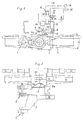
- Agricultural tractor With a lateral distance to the median longitudinal plane Agricultural tractor is in two in the vehicle longitudinal direction swivel bearings 1, 2 supported one behind the other on the chassis a wishbone arrangement 3 pivotally mounted.
- An in Vehicle longitudinal direction forward stub 3a of the Handlebar assembly 3 forms together with one mounted thereon Rigid axis 4, of which only a middle part and a part of the steering linkage is shown, a self-aligning bearing 5, around which the Rigid axis 4 is pendulum corresponding to the angle a.
- both articulation points of the Hydraulic cylinder 6 in the neutral position shown Rigid axis 4 are at least approximately the same height.
- the Hydraulic cylinder 6 for the rebounding and rebounding Handlebar assembly 3 is not an obstacle, since it is about his chassis-side pivot point swiveled.
- a displaceable in the hydraulic cylinder 6 with the piston rod 6a connected piston divides the cylinder interior into known way in two pressure rooms, in the pressure medium lines 10, 11 lead into.
- Both pressure medium lines go from an assigned, in a locked position or a Open position switchable directional valve 12, 13 from that on a pressure medium line 15 and a starting from a pump 14 one leading to a pressure medium container 16 Pressure fluid line 17 is connected.
- the directional control valves 12, 13 can be controlled electrically by means of a control device 18, which the requirements of the vehicle driver with regard to desired pendulum type of the rigid axis 4 in corresponding signals the directional control valves 12, 13 implements.
- Valve 12 Valve 13 Possibility of movement a a Swinging of the rigid axle blocked in a set pendulum position b b free commuting b a Swiveling the rigid axis counterclockwise into a desired pendulum position a b Swiveling the rigid axis clockwise into a desired pendulum position
- a Hydraulic cylinder 6 associated position sensor 19 for the relative Position of the piston in or the relative position of the piston rod 6a connected to the hydraulic cylinder 6. This allows Required in the switch position b / b of the directional control valves 12, 13 in Free swing achievable swing angle of the rigid axis 4 Pendulum angle smaller than the max. Pendulum angle ⁇ can be set.
- FIG. 3 differs from that 1 in that instead of a double-acting Hydraulic cylinder two single-acting hydraulic cylinders 20, 21 are used.
- Each of these hydraulic cylinders is one of the directional control valves 12, 13 assigned, depending on the Switch position of the directional valve in question is its only pressure chamber either with the pump 14 or the pressure medium container 16 connected is.
- switchable directional valves can increase the pendulum capacity of the Rigid axis 4 can be influenced in the desired manner.
Landscapes
- Engineering & Computer Science (AREA)
- Mechanical Engineering (AREA)
- Vehicle Body Suspensions (AREA)
- Arrangement Or Mounting Of Propulsion Units For Vehicles (AREA)
Abstract
Description
Die Erfindung betrifft eine Einrichtung zum Begrenzen der Pendelbewegung einer Starrachse eines Nutzfahrzeuges, insbesondere eines Ackerschleppers, die über ein Pendellager an einer gegenüber dem Fahrgestell des Fahrzeuges abgefederten Lenkeranordnung aufgehängt ist, wobei die Pendelbewegungen der Starrachse begrenzt sind durch an dieser angreifende Anschlagelemente, die mit fahrgestellseitigen Druckstützen zusammenwirken.The invention relates to a device for limiting the Pendulum motion of a rigid axle of a commercial vehicle, especially an agricultural tractor, which has a self-aligning bearing one sprung against the chassis of the vehicle Handlebar assembly is suspended, the pendulum movements of the Rigid axles are limited by attacking them Stop elements with chassis-side pressure supports work together.
Mit einer aus der DE 39 01 757 C2 bekannten Einrichtung dieser Art soll nicht nur die Pendelbewegung der Starrachse, sondern auch deren Ein- und Ausfederung begrenzt werden. Deshalb sind die Anschlagelemente und Druckstützen so ausgestaltet, daß sie bei eingefederter Starrachse als Druckanschlag und bei ausgefederter Starrachse als Zuganschlag wirken. Die Starrachse kann somit innerhalb eines vorgegebenen begrenzten Federweges frei federn und, zumindest in nur wenig ein- oder ausgefedertem Zustand, ungehindert pendeln. Mit zunehmender Annäherung an die Federungsendlagen ist die Pendelbeweglichkeit der Starrachse allerdings stark eingeschränkt, bis sie schließlich bei max. Ein- und Ausfederung vollständig unterbunden ist. Beim schnellen Fahren auf relativ unebenem Gelände ist daher mit erheblichen Einbußen beim Fahrkomfort zu rechnen. With a device known from DE 39 01 757 C2 Art should not only be the pendulum motion of the rigid axle, but their deflection and deflection are also limited. That is why the stop elements and pressure supports designed so that they with a sprung rigid axle as a pressure stop and at spring-loaded rigid axle act as a train stop. The rigid axle can thus within a predetermined limited travel spring freely and, at least in only slightly compressed or rebounded Condition, commute freely. With increasing approach to the Suspension end positions is the pendulum mobility of the rigid axle however severely restricted until they finally reach max. Deflection and rebound is completely prevented. At the fast driving on relatively uneven terrain is therefore included significant losses in driving comfort.
Die bekannte Einrichtung erlaubt es zudem nicht, die Starrachse in einer bestimmten Pendelstellung festzustellen, um die Sicherheit gegen Umsturz beim Befahren von quer zur Fahrtrichtung abfallendem Gelände zu erhöhen.The known device also does not allow the rigid axle in a certain pendulum position to determine the Safety against overturning when driving across the street Increase the direction of the descending terrain.
Aufgabe der Erfindung ist, eine Einrichtung der Eingangs beschriebenen Art zu schaffen, die es bei unbehinderter freier Federung wahlweise ermöglicht, die Starrachse in einer einstellbaren Pendelstellung festzusetzen oder über ihren gesamten Federungsweg frei und uneingeschränkt pendeln zu lassen.The object of the invention is to set up the input described Way of creating free it with the unhindered Suspension optionally allows the rigid axle in one adjustable pendulum position or above their the entire suspension travel is free and unrestricted to let.
Die Lösung dieser Aufgabe besteht darin, daß oberhalb des Pendellagers an einer Anlenkstelle der Starrachse mindestens ein in Fahrzeugquerrichtung verlaufender, gesteuert druckbeaufschlagbarer Hydraulikzylinder angelenkt ist, der sich an einer fahrgestellseitigen, bei nicht eingefederter Lenkeranordnung zumindest annähernd in gleicher Höhe wie die Anlenkstelle (Bolzen) an der Starrachse liegenden Anlenkstelle (Bolzen) abstützt.The solution to this problem is that above the Self-aligning bearings at least one articulation point of the rigid axle a running in the vehicle transverse direction, controlled pressurizable hydraulic cylinder is articulated on a chassis side, when not sprung Handlebar arrangement at least approximately at the same height as that Articulation point (bolt) on the rigid axle (Bolt) supports.
Eine solche Einrichtung ermöglicht es, die Pendelfähigkeit der Starrachse und damit das Fahrverhalten des Fahrzeuges den gegebenen Bodenverhältnissen anzupassen, ohne die Federung zu beeinflussen. Für schnelle Transportfahrten auf relativ ebener Fahrbahn kann die Pendelung der Starrachse auf ihre horizontalen Mittelstellung begrenzt werden, und so insbesondere das Durchfahren von Kurven sicherer gestaltet werden. Für Arbeitsfahrten entlang geneigter Flächen kann die Starrachse in ihrer Neutralstellung oder in geringer Schrägstellung festgestellt werden, um so ebenfalls die Kippsicherheit zu erhöhen.Such a device enables the pendulum ability of the Rigid axle and thus the driving behavior of the vehicle adapt to given ground conditions without the suspension influence. For fast transport trips on a relatively flat surface The oscillation of the rigid axle on its roadway horizontal center position are limited, and so in particular driving through curves is made safer become. For work trips along inclined surfaces, the Rigid axle in its neutral position or less Inclination can be determined, so too the Increasing tipping safety.
Aus den Unteransprüchen gehen weitere Ausgestaltungen der Erfindung hervor.Further refinements of the Invention.
Die Erfindung wird im folgenden an Hand von Zeichnungen näher erläutert. Es zeigen
- Fig. 1
- eine Ansicht einer Starrachse mit einem doppeltwirkenden Hydraulikzylinder zur Beeinflussung der Pendelbewegung in Fahrzeuglängsrichtung gesehen,
- Fig. 2
- eine Ansicht der Starrachse gemäß Fig. 1 von oben und
- Fig. 3
- eine Ansicht einer Starrachse entspr. Fig. 1 mit zwei einfachwirkenden Hydraulikzylindern.
- Fig. 1
- a view of a rigid axle with a double-acting hydraulic cylinder to influence the pendulum movement in the longitudinal direction of the vehicle,
- Fig. 2
- a view of the rigid axis of FIG. 1 from above and
- Fig. 3
- a view of a rigid axle corresponds to FIG. 1 with two single-acting hydraulic cylinders.
Mit seitlichem Abstand zur Längsmittelebene eines
Ackerschleppers ist in zwei in Fahrzeuglängsrichtung
hintereinander am Fahrgestell abgestützten Schwenklagern 1, 2
eine Querlenkeranordnung 3 verschwenkbar gelagert. Ein in
Fahrzeuglängsrichtung nach vorn weisender Achsstummel 3a der
Lenkeranordnung 3 bildet gemeinsam mit einer darauf gelagerten
Starrachse 4, von der lediglich ein mittlerer Teil und ein Teil
des Lenkgestänges gezeigt ist, ein Pendellager 5, um das die
Starrachse 4 entsprechend dem Winkel a pendelbar ist. Beim Ein-
und Ausfedern der Lenkeranordnung 3 bewegt sich das Pendellager
5 annähernd in der Längsmittelebene des Fahrzeuges in
vertikaler Richtung, wie dies der Doppelpfeil andeutet.With a lateral distance to the median longitudinal plane
Agricultural tractor is in two in the vehicle longitudinal
Oberhalb des Pendellagers 5 sind an der Starrachse 4 zwei
Lageraugen 4a, 4b angebracht, an denen, wie aus dem
Ausführungsbeispiel nach Fig. 1 hervorgeht, das freie Ende der
Kolbenstange 6a eines doppeltwirkenden Hydraulikzylinders 6
mittels eines Bolzens 7 angelenkt ist. Im anderen Endbereich
ist der Hydraulikzylinder 6 über einen Bolzen 8 am Fahrgestell
9 des Fahrzeuges angelenkt, wobei beide Anlenkstellen des
Hydraulikzylinders 6 in der gezeigten Neutralstellung der
Starrachse 4 zumindest annähernd in gleicher Höhe liegen.
Infolge dieser annähernd horizontalen Lage bildet der
Hydraulikzylinder 6 für die ein- und ausfedernde
Lenkeranordnung 3 kein Hindernis, da er dabei um seine
fahrgestellseitige Anlenkstelle verschwenkt.Above the self-aligning bearing 5 there are two on the
Ein im Hydraulikzylinder 6 verschiebbarer, mit der Kolbenstange
6a verbundener Kolben unterteilt den Zylinderinnenraum in
bekannter Weise in zwei Druckräume, in die Druckmittelleitungen
10, 11 einmünden. Beide Druckmittelleitungen gehen jeweils von
einem zugeordneten, in eine Sperrstellung oder eine
Durchgangsstellung schaltbaren Wegeventil 12, 13 aus, das an
eine von einer Pumpe 14 ausgehende Druckmittelleitung 15 und
eine zu einem Druckmittelbehälter 16 führende
Druckmittelleitung 17 angeschlossen ist. Die Wegeventile 12, 13
sind elektrisch ansteuerbar mittels einer Steuereinrichtung 18,
die die Vorgaben des Fahrzeugführers hinsichtlich der
gewünschten Pendelart der Starrachse 4 in entspr. Signale an
die Wegeventile 12, 13 umsetzt.A displaceable in the
Der nachstehenden Tabelle sind die in Abhängigkeit von der
Schaltstellung a oder b der Wegeventile 12, 13 wählbaren
Bewegungsmöglichkeiten der Starrachse zu entnehmen:
Welche dieser Bewegungsmöglichkeiten auch gewählt wird, die
Funktionsweise der Federung der Lenkeranordnung 3 bleibt davon
unberührt. Dies selbst dann, wenn beide Wegeventile 12, 13 die
Schaltstellung a einnehmen und demzufolge der Hydraulikzylinder
6 in beiden Richtungen blockiert ist, um die Pendelung der
Starrachse 4 zu unterbinden. In diesem Fall verschwenkt der
Hydraulikzylinder 6 um den Bolzen 8 entsprechend dem Weg, den
das Pendellager 5 beim Ein- und Ausfedern in Richtung des
Doppelpfeils zurücklegt. Hierbei wird der Bolzen 7 auf einer
schwach gekrümmten Bahn geführt, wodurch die Starrachse 3
während des Ein- und Ausfederns unmerklich um das Pendellager 5
pendelt.Whichever of these movement options is chosen, the
Operation of the suspension of the
An die Steuereinrichtung 18 ist außerdem ein dem
Hydraulikzylinder 6 zugehöriger Lagesensor 19 für die relative
Lage des Kolbens im bzw. die relative Stellung der Kolbenstange
6a zum Hydraulikzylinder 6 angeschlossen. Hierdurch kann bei
Bedarf der in der Schaltstellung b/b der Wegeventile 12, 13 in
freier Pendelung erzielbare Pendelwinkel der Starrachse 4 auf
Pendelwinkel kleiner als der konstruktiv vorgegebene max.
Pendelwinkel α eingestellt werden.To the
Das Ausführungsbeispiel nach Fig. 3 unterscheidet sich von dem
gemäß Fig. 1 dadurch, daß an Stelle eines doppeltwirkenden
Hydraulikzylinders zwei einfachwirkende Hydraulikzylinder 20,
21 zur Anwendung kommen. Jedem dieser Hydraulikzylinder ist
eines der Wegeventile 12, 13 zugeordnet, über das je nach
Schaltstellung des betr. Wegeventils sein einziger Druckraum
entweder mit der Pumpe 14 oder dem Druckmittelbehälter 16
verbunden ist. Je nach Schaltstellung der unabhängig
voneinander durch eine nicht gezeigte Steuereinrichtung
schaltbaren Wegeventile kann so die Pendelfähigkeit der
Starrachse 4 in der gewünschten Weise beeinflusst werden.3 differs from that
1 in that instead of a double-acting
Hydraulic cylinder two single-acting
Claims (4)
- Device for limiting the oscillating movement of a rigid axis (4) of a commercial vehicle, in particular of a farming tractor, which is suspended by means of a pendulum bearing (5) on a steering arrangement (3), which is spring-mounted relative to the chassis (9) of the vehicle, the oscillating movements of the rigid axis being limited by stop elements which act thereon and which co-operate with pressure supports located on the chassis side, characterised in that there is coupled above the pendulum bearing (5) to a coupling point of the rigid axis (4) at least one hydraulic cylinder (6) which extends in the transverse direction of the vehicle and which can be pressure-activated in a controlled manner and which is supported on a coupling point (8) which is located on the chassis side and which is at least approximately at the same height as the coupling point (7) on the rigid axis (4) when the steering arrangement (3) is not compressed.
- Device according to claim 1, characterised in that two single-acting hydraulic cylinders (20, 21), directed against each other, act on the coupling point of the rigid axis (4).
- Device according to claim 1 or claim 2, characterised by a control device (18) for the pressure-activation of the hydraulic cylinder(s) (6, 20, 21), which has a signal-connection to a device, which supplies a signal which corresponds to the oscillating position of the rigid axis (4), and which activates hydraulic locking of the hydraulic cylinder(s) (6, 20, 21) when a predetermined oscillating position of the rigid axis (4) is reached.
- Device according to claim 3, characterised in that the hydraulic cylinder(s) (6, 20) is/are fitted with a position sensor (18) for determining the position of the piston rod (6a).
Applications Claiming Priority (2)
| Application Number | Priority Date | Filing Date | Title |
|---|---|---|---|
| DE19616302A DE19616302A1 (en) | 1996-04-24 | 1996-04-24 | Device for limiting the pendulum movement of a rigid axle of a commercial vehicle, in particular an agricultural tractor |
| DE19616302 | 1996-04-24 |
Publications (3)
| Publication Number | Publication Date |
|---|---|
| EP0803384A2 EP0803384A2 (en) | 1997-10-29 |
| EP0803384A3 EP0803384A3 (en) | 1999-04-21 |
| EP0803384B1 true EP0803384B1 (en) | 2000-11-22 |
Family
ID=7792265
Family Applications (1)
| Application Number | Title | Priority Date | Filing Date |
|---|---|---|---|
| EP97105504A Expired - Lifetime EP0803384B1 (en) | 1996-04-24 | 1997-04-03 | Device for limiting the oscillating motion of a rigid axle of a commercial vehicle, especially of an agricultural tractor |
Country Status (3)
| Country | Link |
|---|---|
| EP (1) | EP0803384B1 (en) |
| AT (1) | ATE197694T1 (en) |
| DE (2) | DE19616302A1 (en) |
Cited By (1)
| Publication number | Priority date | Publication date | Assignee | Title |
|---|---|---|---|---|
| KR100952534B1 (en) * | 2005-09-29 | 2010-04-12 | 가부시끼 가이샤 구보다 | Wheel type work machine |
Families Citing this family (6)
| Publication number | Priority date | Publication date | Assignee | Title |
|---|---|---|---|---|
| GB2336573B (en) * | 1998-04-21 | 2002-02-13 | Agco Gmbh & Co | Utility vehicle with rigid axle |
| IT1302736B1 (en) * | 1998-10-15 | 2000-09-29 | Carraro Spa | OSCILLATING AXLE SUSPENSION SYSTEM, IN PARTICULAR TRACTORS. |
| IT1304143B1 (en) * | 1998-12-02 | 2001-03-07 | New Holland Italia Spa | FRONT AXLE ASSEMBLY OF A TRACTOR, OR SIMILAR VEHICLE. |
| EP1234695A1 (en) * | 2001-02-23 | 2002-08-28 | Dana Italia S.p.A | Damped suspended axle, in particular for agricultural machines, industrial vehicles and the like |
| PL2218835T3 (en) * | 2009-02-12 | 2013-04-30 | Toine Brock Constructie/Mechanisatie B V | Shovel loader comprising two hinged frames. |
| BE1018654A3 (en) * | 2009-02-12 | 2011-06-07 | Didden Luc | LOADER. |
Family Cites Families (8)
| Publication number | Priority date | Publication date | Assignee | Title |
|---|---|---|---|---|
| US4053171A (en) * | 1976-04-29 | 1977-10-11 | Westinghouse Air Brake Company | Spring suspension arrangement for off-road vehicles |
| US4393959A (en) * | 1980-12-10 | 1983-07-19 | Allis-Chalmers Corporation | Hydraulic stabilizer for axle on mast lift vehicle |
| DE3901757A1 (en) * | 1988-01-29 | 1989-08-10 | Zahnradfabrik Friedrichshafen | Suspension of a rigid axle of a tractor |
| DE9017845U1 (en) * | 1990-08-08 | 1992-03-26 | MAN Nutzfahrzeuge AG, 8000 München | Rigid axle with hydropneumatic suspension struts in commercial vehicles |
| US5082085A (en) * | 1990-08-30 | 1992-01-21 | Up-Right, Inc. | Platform leveling apparatus |
| DE4129715A1 (en) * | 1991-09-06 | 1993-03-11 | Kloeckner Humboldt Deutz Ag | Linkage for sprung steered axle on farm vehicle - uses scissor lever mechanism to limit spring deflection |
| DE4235264B4 (en) * | 1992-10-20 | 2004-07-08 | Same Deutz-Fahr S.P.A., Treviglio | Hydraulic front axle locking and locking for an agricultural vehicle |
| FR2702012B1 (en) * | 1993-02-25 | 1995-05-24 | Sacmi | Hydraulic device for controlling the oscillations of a moving body and application to the oscillating train of a motor vehicle. |
-
1996
- 1996-04-24 DE DE19616302A patent/DE19616302A1/en not_active Withdrawn
-
1997
- 1997-04-03 AT AT97105504T patent/ATE197694T1/en not_active IP Right Cessation
- 1997-04-03 DE DE59702651T patent/DE59702651D1/en not_active Expired - Fee Related
- 1997-04-03 EP EP97105504A patent/EP0803384B1/en not_active Expired - Lifetime
Cited By (1)
| Publication number | Priority date | Publication date | Assignee | Title |
|---|---|---|---|---|
| KR100952534B1 (en) * | 2005-09-29 | 2010-04-12 | 가부시끼 가이샤 구보다 | Wheel type work machine |
Also Published As
| Publication number | Publication date |
|---|---|
| DE59702651D1 (en) | 2000-12-28 |
| DE19616302A1 (en) | 1997-10-30 |
| EP0803384A3 (en) | 1999-04-21 |
| ATE197694T1 (en) | 2000-12-15 |
| EP0803384A2 (en) | 1997-10-29 |
Similar Documents
| Publication | Publication Date | Title |
|---|---|---|
| EP0932512B1 (en) | Pendular spring mounted axle suspension | |
| DE3826930C2 (en) | Suspension system | |
| EP0390787B1 (en) | Tractor useful in agriculture or civil engineering with a steerable rigid axle | |
| EP0512550B1 (en) | Spring suspension of a steering axle | |
| DE10133424A1 (en) | Rear axle for vehicle has upper two of five individual rods set in front of spring and/or damper element mounted between vehicle superstructure and one of lower guide rods | |
| DE2256934A1 (en) | VEHICLE SUSPENSION, IN PARTICULAR FOR A MOTOR VEHICLE | |
| DE3514823A1 (en) | INDEPENDENT WHEEL SUSPENSION FOR MOTOR VEHICLES | |
| EP1302342A2 (en) | Suspension system for a pendular axle | |
| EP0803384B1 (en) | Device for limiting the oscillating motion of a rigid axle of a commercial vehicle, especially of an agricultural tractor | |
| DE19918146A1 (en) | Vehicle with a rigid axle | |
| DE4235264B4 (en) | Hydraulic front axle locking and locking for an agricultural vehicle | |
| DE10210556A1 (en) | vehicle axle | |
| EP0647554A2 (en) | Deactivatable axle steering | |
| DE3511336A1 (en) | CONSTRUCTION MACHINE DRIVABLE ON WHEELS WITH ARTICULATED STEERING, LIKE SHOVEL LOADER, PLANING VEHICLE OR THE LIKE. | |
| DE2723672A1 (en) | VEHICLE WHEEL SUSPENSION SYSTEM | |
| DE102007025598A1 (en) | Vehicle with pendulum axis | |
| DE60116179T2 (en) | Machine for transporting loads | |
| DE69809847T2 (en) | Control device and hydraulic cylinder for a swiveling commercial vehicle axle | |
| EP0754576B1 (en) | Suspension of the rigid axle of an off-road vehicle | |
| EP0259801B1 (en) | Hitching device for an agricultural tractor | |
| CH675102A5 (en) | ||
| DE202005011305U1 (en) | Bottom drag-link sideward stabilization device for agriculture tractor, has stopper, designed at connecting links, coming into preset height of bottom drag line and/or back stays at connecting link bolts | |
| DE69817509T2 (en) | Spring-loaded spreader | |
| DE3532006C2 (en) | ||
| DE69601232T2 (en) | Agricultural machine with sprung undercarriage |
Legal Events
| Date | Code | Title | Description |
|---|---|---|---|
| PUAI | Public reference made under article 153(3) epc to a published international application that has entered the european phase |
Free format text: ORIGINAL CODE: 0009012 |
|
| AK | Designated contracting states |
Kind code of ref document: A2 Designated state(s): AT DE FR GB IT |
|
| RAP1 | Party data changed (applicant data changed or rights of an application transferred) |
Owner name: AGCO GMBH & CO |
|
| RAP1 | Party data changed (applicant data changed or rights of an application transferred) |
Owner name: AGCO GMBH & CO |
|
| RAP1 | Party data changed (applicant data changed or rights of an application transferred) |
Owner name: AGCO GMBH & CO. |
|
| PUAL | Search report despatched |
Free format text: ORIGINAL CODE: 0009013 |
|
| AK | Designated contracting states |
Kind code of ref document: A3 Designated state(s): AT DE FR GB IT |
|
| 17P | Request for examination filed |
Effective date: 19991006 |
|
| GRAG | Despatch of communication of intention to grant |
Free format text: ORIGINAL CODE: EPIDOS AGRA |
|
| GRAG | Despatch of communication of intention to grant |
Free format text: ORIGINAL CODE: EPIDOS AGRA |
|
| GRAH | Despatch of communication of intention to grant a patent |
Free format text: ORIGINAL CODE: EPIDOS IGRA |
|
| 17Q | First examination report despatched |
Effective date: 20000518 |
|
| GRAH | Despatch of communication of intention to grant a patent |
Free format text: ORIGINAL CODE: EPIDOS IGRA |
|
| GRAA | (expected) grant |
Free format text: ORIGINAL CODE: 0009210 |
|
| AK | Designated contracting states |
Kind code of ref document: B1 Designated state(s): AT DE FR GB IT |
|
| REF | Corresponds to: |
Ref document number: 197694 Country of ref document: AT Date of ref document: 20001215 Kind code of ref document: T |
|
| REF | Corresponds to: |
Ref document number: 59702651 Country of ref document: DE Date of ref document: 20001228 |
|
| ET | Fr: translation filed | ||
| ITF | It: translation for a ep patent filed | ||
| GBT | Gb: translation of ep patent filed (gb section 77(6)(a)/1977) |
Effective date: 20010222 |
|
| PLBE | No opposition filed within time limit |
Free format text: ORIGINAL CODE: 0009261 |
|
| STAA | Information on the status of an ep patent application or granted ep patent |
Free format text: STATUS: NO OPPOSITION FILED WITHIN TIME LIMIT |
|
| 26N | No opposition filed | ||
| REG | Reference to a national code |
Ref country code: GB Ref legal event code: IF02 |
|
| PGFP | Annual fee paid to national office [announced via postgrant information from national office to epo] |
Ref country code: AT Payment date: 20060309 Year of fee payment: 10 |
|
| PG25 | Lapsed in a contracting state [announced via postgrant information from national office to epo] |
Ref country code: AT Free format text: LAPSE BECAUSE OF NON-PAYMENT OF DUE FEES Effective date: 20070403 |
|
| PGFP | Annual fee paid to national office [announced via postgrant information from national office to epo] |
Ref country code: IT Payment date: 20090429 Year of fee payment: 13 Ref country code: FR Payment date: 20090414 Year of fee payment: 13 Ref country code: DE Payment date: 20090422 Year of fee payment: 13 |
|
| PGFP | Annual fee paid to national office [announced via postgrant information from national office to epo] |
Ref country code: GB Payment date: 20090421 Year of fee payment: 13 |
|
| GBPC | Gb: european patent ceased through non-payment of renewal fee |
Effective date: 20100403 |
|
| REG | Reference to a national code |
Ref country code: FR Ref legal event code: ST Effective date: 20101230 |
|
| PG25 | Lapsed in a contracting state [announced via postgrant information from national office to epo] |
Ref country code: DE Free format text: LAPSE BECAUSE OF NON-PAYMENT OF DUE FEES Effective date: 20101103 |
|
| PG25 | Lapsed in a contracting state [announced via postgrant information from national office to epo] |
Ref country code: IT Free format text: LAPSE BECAUSE OF NON-PAYMENT OF DUE FEES Effective date: 20100403 Ref country code: GB Free format text: LAPSE BECAUSE OF NON-PAYMENT OF DUE FEES Effective date: 20100403 |
|
| PG25 | Lapsed in a contracting state [announced via postgrant information from national office to epo] |
Ref country code: FR Free format text: LAPSE BECAUSE OF NON-PAYMENT OF DUE FEES Effective date: 20100430 |