EP0803368A1 - System und Verfahren zur Bestimmung der Anwesenheit von Tinten die unsichtbar sind für optischen Fühler - Google Patents
System und Verfahren zur Bestimmung der Anwesenheit von Tinten die unsichtbar sind für optischen Fühler Download PDFInfo
- Publication number
- EP0803368A1 EP0803368A1 EP97302597A EP97302597A EP0803368A1 EP 0803368 A1 EP0803368 A1 EP 0803368A1 EP 97302597 A EP97302597 A EP 97302597A EP 97302597 A EP97302597 A EP 97302597A EP 0803368 A1 EP0803368 A1 EP 0803368A1
- Authority
- EP
- European Patent Office
- Prior art keywords
- ink
- invisible
- sensor
- printing
- visible
- Prior art date
- Legal status (The legal status is an assumption and is not a legal conclusion. Google has not performed a legal analysis and makes no representation as to the accuracy of the status listed.)
- Granted
Links
Images


Classifications
-
- B—PERFORMING OPERATIONS; TRANSPORTING
- B41—PRINTING; LINING MACHINES; TYPEWRITERS; STAMPS
- B41J—TYPEWRITERS; SELECTIVE PRINTING MECHANISMS, i.e. MECHANISMS PRINTING OTHERWISE THAN FROM A FORME; CORRECTION OF TYPOGRAPHICAL ERRORS
- B41J2/00—Typewriters or selective printing mechanisms characterised by the printing or marking process for which they are designed
- B41J2/005—Typewriters or selective printing mechanisms characterised by the printing or marking process for which they are designed characterised by bringing liquid or particles selectively into contact with a printing material
- B41J2/01—Ink jet
- B41J2/21—Ink jet for multi-colour printing
- B41J2/2107—Ink jet for multi-colour printing characterised by the ink properties
- B41J2/2114—Ejecting specialized liquids, e.g. transparent or processing liquids
-
- B—PERFORMING OPERATIONS; TRANSPORTING
- B41—PRINTING; LINING MACHINES; TYPEWRITERS; STAMPS
- B41J—TYPEWRITERS; SELECTIVE PRINTING MECHANISMS, i.e. MECHANISMS PRINTING OTHERWISE THAN FROM A FORME; CORRECTION OF TYPOGRAPHICAL ERRORS
- B41J2/00—Typewriters or selective printing mechanisms characterised by the printing or marking process for which they are designed
- B41J2/005—Typewriters or selective printing mechanisms characterised by the printing or marking process for which they are designed characterised by bringing liquid or particles selectively into contact with a printing material
- B41J2/01—Ink jet
- B41J2/21—Ink jet for multi-colour printing
- B41J2/2132—Print quality control characterised by dot disposition, e.g. for reducing white stripes or banding
- B41J2/2135—Alignment of dots
Definitions
- This invention relates generally to machines and procedures for printing text or graphics in color on printing media such as paper, transparency stock, or other glossy media; and more particularly to a system and method for determining presence and location, on a printing medium, of ink that is of a color invisible to an optical sensor.
- ink that is invisible to a sensor we implicitly refer to observations of ink coated onto some particular printing medium under some particular illumination.
- the printing medium is ordinarily white paper and the illumination is bright green light from a common and industrially popular light-emitting diode that emits with a peak at 560 nm.
- contrast is evaluated within the effective waveband established by the illumination, sensor sensitivity and printing-medium background. As will be seen, our invention artificially elevates such contrast.
- the invention is useful particularly but not exclusively in scanning thermal-inkjet printers that construct text or images from individual ink spots created on a printing medium, in a two-dimensional pixel array.
- problems may arise when the functions of equipment modules (illuminators and sensors) initially designed into a printer for one use, such as for example merely sensing registration marks printed in black ink, may be expanded to handle some of the other tasks as well.
- equipment modules illumination and sensors
- such other tasks may include, for example, checking ink density for several marking implements that print in various colors respectively.
- Some green or red light-emitting diodes are popular for their low cost and reliable operation ⁇ but magenta ink on white paper may be invisible under red light, and yellow on white paper may be nearly invisible under green light.
- the present invention introduces such refinement.
- the present invention has system and method aspects or facets. They are preferably employed together to optimize the benefits of the invention.
- the invention is a system for determining presence, on a printing medium, of ink that is invisible to an optical sensor.
- the system includes an optical sensor. It also includes some means for printing, using an ink that is visible to the sensor, a fractional fill pattern on a region of such printing medium. For generality and breadth, but also for clarity relative to other elements of invention, we will identify these means as the "first printing means".
- the system also includes some means for printing, using such ink that is invisible to the sensor, indicia on particular portions of the same region. These means we will call “the second printing means”.
- Bleed, or running together of the liquids, of the two inks tends to convert the fractional fill pattern into a solid fill, within those particular portions. As will be seen from the detailed description that follows, this action is in fact only a tendency ⁇ large gaps remain between solidly filled regions.
- the system also includes some means for then locating, or in other words localizing, the particular portions by operating the optical sensor to respond to areas where bleed has converted the fractional fill pattern into a relatively more solid fill.
- the invisible ink has been made visible to the sensor using resources that are already available within the system ⁇ without special light sources, sensors or filters.
- the first means print the visible-ink fractional pattern in the form of aggregations of multiple adjacent pixels, rather than in the form of individual, mutually separated pixels. This consolidation seems to enhance the liquid overload along the perimeter of the inked area units ⁇ and thereby enhance the response to additional liquid when added by the invisible ink.
- the aggregations be spaced apart by spaces ⁇ that is to say, uninked (with the visible ink) distances on the printing medium ⁇ which also occupy multiple adjacent pixels. Breaking up the aggregations in this way appears to enhance the ratio of perimeter to area so that, again, optimum bleed response is obtained to addition of liquid by the invisible ink.
- the visible-ink fractional pattern should be printed at a fill density between fifteen and seventy-five percent.
- An ideal fill density is roughly twenty-five percent.
- the invention works best if the system overprints the invisible ink over the visible ink.
- the second printing means operate after the first printing means operate.
- the invention is particularly applicable to enhancing performance of a system that determines positional deviation of a marking implement ⁇ particularly an implement which marks in the invisible ink.
- the second means print a series of positional-calibration indicia in the invisible ink.
- the indicia comprise diagonal lines, as explained in the above-mentioned related patent document of Sievert et al.
- the apparatus includes some means for responding to the locating means to adjust the position of printing with the second means ⁇ to compensate for such determined positional deviation.
- the invention is a method for determining presence, on a printing medium, of ink that is invisible to an optical sensor.
- the method includes the step of printing, using an ink that is visible to the sensor, a fractional fill pattern on a region of such printing medium.
- the method also includes the step of printing, using such ink that is invisible to the sensor, indicia on particular portions of the same region. Bleed of the two inks together tends to convert the fractional fill pattern into a solid fill, within the particular portions.
- the method also includes the step of then locating the particular portions by operating the optical sensor to respond to areas where bleed has converted the fractional fill pattern into a relatively more-solid fill.
- the invention is a system for determining and using presence of ink that is invisible to an optical sensor.
- This system includes an optical sensor and a printing medium.
- It also includes some means, coated on the printing medium, for interacting with the ink that is invisible to the sensor. These coated means are for interacting with the ink to form indicia that are visible to the sensor.
- the system includes means for printing a pattern of calibration ink deposits on the coated means. These printing means operate using the ink that is invisible to the sensor.
- This third aspect of the invention does not necessarily depend upon the statistics inherent in wicking-together of a fractional-fill tone. It therefore may precisely disclose the position of the invisible ink with fewer sensor passes.
- Figs. 1 and la indicate, preferred embodiments of the invention are advantageously incorporated into an automatic printer, as for instance a thermal-inkjet desktop printer or large-format plotter respectively.
- the printer or plotter 10 includes a housing 12, with a control panel 20.
- the working parts may be mounted on a stand 14; and the housing 12 has left and right drive-mechanism enclosures 16 and 18.
- the control panel 20 is mounted on the right enclosure 18.
- a carriage assembly 100 (which for the large-format plotter of Fig. la is illustrated in phantom under a transparent cover 22), is adapted for reciprocal motion along a slider rod or carriage bar 24 (also in phantom for the plotter).
- the position of the carriage assembly 100 in a horizontal or carriage-scan axis is determined by a carriage positioning mechanism (not shown) with respect to an encoder strip (not shown), as is very well known in the art.
- the carriage 100 includes four stalls or bays for automatic marking implements such as inkjet pens that print with ink of different colors. These are for example black ink and three chromatic-primary (e.g. yellow, magenta and cyan) inks, respectively.
- automatic marking implements such as inkjet pens that print with ink of different colors. These are for example black ink and three chromatic-primary (e.g. yellow, magenta and cyan) inks, respectively.
- Fig. 1 shows, for the desktop printer, a single representative pen 102 ⁇ and the remaining three empty bays marked with reference numbers in parentheses thus: (104), (106) and (108).
- Fig. 1a shows all four pens 102, 104, 106, and 108.
- the colors from the three chromatic-color inkjet pens are typically used in subtractive combinations by overprinting to obtain secondary colors; and in additive combinations by adjacent printing to obtain other colors.
- the carriage assembly 100 includes a carriage 101 (Fig. 2) adapted for reciprocal motion on a slider bar or carriage rod 103.
- a carriage 101 Fig. 2 adapted for reciprocal motion on a slider bar or carriage rod 103.
- a front slider rod or carriage bar 103 For the much greater transverse span in the large-format plotter (Fig. 2a), there are a front slider rod or carriage bar 103 and a like rear rod/bar 105.
- a representative first pen cartridge 102 is shown mounted in a first stall of the carriage 101.
- a printing medium 30 such as paper is positioned along a vertical or printing-medium-advance axis by a medium-advance drive mechanism (not shown).
- a medium-advance drive mechanism not shown.
- the carriage-scan axis is denoted the x axis and the medium-advance axis is denoted the y axis; and for large-format plotters conversely.
- Printing-medium and carriage position data go to a processor on a circuit board that is preferably on the carriage assembly 100, for the large plotter, or elsewhere in the chassis for the desktop model.
- the carriage assembly 100 also may hold circuitry required for interface to firing circuits (including firing resistors) in the pens.
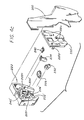
- a sensor module 200 Also mounted to the carriage assembly 100 is a sensor module 200. Note that the inkjet nozzles 107 (Fig. 2) of the representative pen 102, and indeed of each pen, are in line with the sensor module 200.
- test patterns 402, 404, 406, 408 is generated (by activation of selected nozzles in selected pens while the carriage scans across the medium) whenever any of the cartridges is disturbed ⁇ for instance just after a marking implement (e. g. , pen) has been replaced.
- the test patterns are then read by scanning the electrooptical sensor 200 over them, and analyzing the resulting waveforms.
- the sensor module 200 optically senses the test pattern and provides electrical signals to the system processor, indicative of the registration of the portions of the pattern produced by the different marking implements respectively.
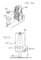
- Figs. 4a through 4d show representative sensor modules 200 utilized in the two preferred embodiments of the lower-numbered drawings.
- Each sensor module 200 includes an optical component holder 222, with a lens 226 (or if preferred a more-complicated focal system with a second lens 228, Fig. 4d, such as that shown by Cobbs et al. ) fixed relative to a detector 240 (Fig. 5).
- First and second light-emitting diodes (LEDs) 232 and 234 are mounted to the sensor module 200, at an angle as shown, along with an amplifier and other circuit elements (not shown).
- the light-emitting diodes and photodetector are of conventional design, and they form a sensing system which can discriminate very well between the presence and the absence of ink, for three of the four marking implements 102, 104, 106, 108 ⁇ namely for the colors cyan, magenta and black.
- the reflectance of this yellow ink, coated on white paper is only a few percent less than the reflectance of the paper alone.
- the sensing system is therefore unable to distinguish cleanly between the corresponding yellow light and the white background of a typical printing medium 30.
- the visible (e. g. , magenta) ink is not laid down in individual isolated pixels 511 (a single pixel is shown separately at 511a to more clearly convey its size), but rather in aggregations or so-called "superpixels" 512, 515 which are typically five pixels square. Some of the aggregations 513 amount to two superpixels, being five pixels wide and ten pixels tall.
- this inking by aggregation 512, 513, 515 has been found preferable for enhancing contrast between areas where invisible ink is later applied and areas where it is not.
- the aggregations 512, 513, 515 are not entirely continuous over the entire image but rather are broken up.
- the columns of double-superpixel aggregations 513 are separated by uninked spaces 514 equal in area to one superpixel. As also explained previously, this ample separation, too, between pixel aggregations has been found preferable in optimizing contrast.
- Ink that might have gone into these superpixel-sized spaces or separations 514 is instead displaced laterally to form columns of single superpixels 512, 515 which are halfway between the columns of double superpixels 513.
- the spaces 516 between columns of single and double superpixels are also five pixels wide.
- the circle 517 drawn superimposed on the pixel and superpixel pattern represents very approximately the area which can be within the field of view of the system sensor at any moment.
- the circle 517 happens to have been placed in a position where shaded pixels are roughly twenty-one percent of the total; however, this is merely an accident of illustration.
- this size can contain even fewer than twenty percent, or more than thirty percent, shaded pixels. On average the number is of course twenty-five percent.
- Fig. 7 pattern is clearly visible in the micrographs of Fig. 8, particularly in view a, where the density of yellow was zero.
- the variations in gray- background tone should be disregarded, as they are primarily an artifact of the reproduction process used to prepare the illustration.
- Associated circuitry stores these signals, averages them as mentioned above, and examines their phase relationships to determine the alignments of the pens for each direction of movement.
- Fourier-transform methods of either the "fast” or “discrete” type, advantageously facilitate this process.
- the Fourier transform of the data is determined and the phase then extracted from the transform by comparison of its real and imaginary parts (i. e. , sine and cosine components).
- real and imaginary parts i. e. , sine and cosine components.
- the system corrects for carriage-axis misalignment ⁇ and print-medium-axis misalignment ⁇ and can be used to correct for offsets due to speed and curvature as well. Further details of these options are discussed at length in the Cobbs et al. documents and so need not be repeated here.
- the Cobbs and Sievert documents further describe, in detail, correction for deviations in the carriage-scan axis, and also correction of offsets in the printing-medium-advance axis and between pens.
- Offsets between pens, along the medium-advance axis, can be corrected by selecting certain nozzles for activation, as described by Cobbs et al. , or by masking the data as between swaths of the marking implements as mentioned by Sievert et al.
- the Cobbs technique has the drawback of requiring extra nozzles; whereas the Sievert technique has the drawback of introducing undesirable variations in colorant-laydown sequence in some regions of the printout, and also somewhat increasing computation complexity and time.
Landscapes
- Engineering & Computer Science (AREA)
- Quality & Reliability (AREA)
- Ink Jet (AREA)
- Accessory Devices And Overall Control Thereof (AREA)
Applications Claiming Priority (2)
| Application Number | Priority Date | Filing Date | Title |
|---|---|---|---|
| US08/636,439 US5980016A (en) | 1996-04-22 | 1996-04-22 | Systems and method for determining presence of inks that are invisible to sensing devices |
| US636439 | 1996-04-22 |
Publications (2)
| Publication Number | Publication Date |
|---|---|
| EP0803368A1 true EP0803368A1 (de) | 1997-10-29 |
| EP0803368B1 EP0803368B1 (de) | 2002-07-17 |
Family
ID=24551917
Family Applications (1)
| Application Number | Title | Priority Date | Filing Date |
|---|---|---|---|
| EP97302597A Expired - Lifetime EP0803368B1 (de) | 1996-04-22 | 1997-04-16 | System und Verfahren zur Bestimmung der Anwesenheit von Tinten die unsichtbar sind für optischen Fühler |
Country Status (3)
| Country | Link |
|---|---|
| US (2) | US5980016A (de) |
| EP (1) | EP0803368B1 (de) |
| DE (1) | DE69713949T2 (de) |
Cited By (8)
| Publication number | Priority date | Publication date | Assignee | Title |
|---|---|---|---|---|
| EP1081629A3 (de) * | 1999-08-30 | 2001-06-06 | Eastman Kodak Company | Verfahren und Artikeln zur Bestimmung der Druckqualität mit unsichtbaren Tinten |
| DE10016203A1 (de) * | 2000-03-31 | 2001-10-11 | Wincor Nixdorf Gmbh & Co Kg | Einrichtung zum Reinigen der Tintendüsen eines Tintendruckkopfes in einem Tintenstrahldrucker |
| EP1308287A1 (de) * | 2001-10-31 | 2003-05-07 | Hewlett Packard Company, a Delaware Corporation | Verfahren und System zur Kalibrierung von Tintenausstosselementen in einer Bilderzeugungsvorrichtung |
| EP1308294A1 (de) * | 2001-10-31 | 2003-05-07 | Hewlett Packard Company, a Delaware Corporation | System und Verfahren zur Detektierung von unsichtbaren Tintentropfen |
| EP1220753A4 (de) * | 1999-05-25 | 2003-08-27 | Silverbrook Res Pty Ltd | Druckpatrone mit maschinenlesbarer tinte |
| DE10306274B4 (de) * | 2002-12-31 | 2007-04-12 | Osram Opto Semiconductors Gmbh | Optisches Sensormodul |
| US7258435B2 (en) | 1999-05-25 | 2007-08-21 | Silverbrook Research Pty Ltd | Inkjet printer with a media tray for sheets of print media and an ink cartridge |
| DE10027177B4 (de) * | 1999-08-23 | 2008-10-09 | Hewlett-Packard Development Co., L.P., Houston | Ausrichtung eines Tintenstrahlstifts für klares Fluid |
Families Citing this family (25)
| Publication number | Priority date | Publication date | Assignee | Title |
|---|---|---|---|---|
| US5980016A (en) * | 1996-04-22 | 1999-11-09 | Hewlett-Packard Company | Systems and method for determining presence of inks that are invisible to sensing devices |
| JP4428752B2 (ja) * | 1999-04-19 | 2010-03-10 | キヤノン株式会社 | 記録装置 |
| US6894794B1 (en) * | 1999-06-24 | 2005-05-17 | Eastman Kodak Company | Method and apparatus for making a print having an invisible coordinate system |
| MXPA02000183A (es) * | 1999-06-30 | 2004-09-10 | Silverbrook Res Pty Ltd | Cuenta de impresora interactiva. |
| US6378976B1 (en) * | 1999-08-23 | 2002-04-30 | Hewlett-Packard Company | Use of an essentially colorless marker to allow evaluation of nozzle health for printing colorless “fixer” agents in multi-part ink-jet images |
| US7301125B2 (en) * | 2001-05-31 | 2007-11-27 | Ric Investments, Llc | Heater for optical gas sensor |
| US6582049B2 (en) | 2001-05-31 | 2003-06-24 | Lexmark International, Inc. | Method and apparatus for detecting the position of an inkjet printhead |
| US6478401B1 (en) | 2001-07-06 | 2002-11-12 | Lexmark International, Inc. | Method for determining vertical misalignment between printer print heads |
| DE10143942A1 (de) * | 2001-09-07 | 2003-03-27 | Wifag Maschf | Prüfmittel und Verfahren zur Kontrolle des Offset- und Digitaldrucks |
| JP3995037B2 (ja) * | 2001-11-28 | 2007-10-24 | 富士フイルム株式会社 | 走査型印刷装置およびそれによる印刷方法 |
| JP3820979B2 (ja) * | 2001-12-17 | 2006-09-13 | ブラザー工業株式会社 | パッチ形成装置およびプログラム |
| US6902265B2 (en) * | 2002-06-28 | 2005-06-07 | Pitney Bowes Inc. | Method for printing high information density machine-readable composite images |
| GB2391306B (en) * | 2002-07-30 | 2006-02-01 | Hewlett Packard Co | Detecting fixer in hardcopy apparatus |
| US6883892B2 (en) * | 2002-10-31 | 2005-04-26 | Hewlett-Packard Development Company, L.P. | Printing apparatus calibration |
| US6948660B2 (en) * | 2002-12-30 | 2005-09-27 | Pitney Bowes Inc. | Method for improving the readability of composite images |
| US6893107B2 (en) * | 2003-01-09 | 2005-05-17 | Hewlett-Packard Development Company, L.P. | Method and system for visualizing printed fluids using indicator media |
| JP4465999B2 (ja) * | 2003-07-29 | 2010-05-26 | セイコーエプソン株式会社 | 印刷装置、吐出検査方法、吐出検査用パターンの形成方法、プログラムおよび印刷システム |
| JP4553344B2 (ja) * | 2003-09-04 | 2010-09-29 | キヤノン株式会社 | 記録装置 |
| GB0321164D0 (en) * | 2003-09-10 | 2003-10-08 | Hewlett Packard Development Co | Methods,apparatus and software for printing location pattern |
| US7517041B2 (en) * | 2003-11-19 | 2009-04-14 | Donald J Palmer | Printing and detecting a fixer pattern on a medium |
| US7918551B2 (en) * | 2006-06-02 | 2011-04-05 | Hewlett-Packard Development Company, L.P. | Ink sets with infrared blockers |
| US7905567B2 (en) * | 2008-05-16 | 2011-03-15 | Avago Technologies Ecbu Ip (Singapore) Pte. Ltd. | Closed-loop printing registration systems, devices, components and methods |
| ES2422979T3 (es) * | 2010-03-25 | 2013-09-16 | Modesto Luengo Bada | Marca, método y sistema para la medición de parámetros de calidad de color |
| US8899712B2 (en) | 2011-08-31 | 2014-12-02 | Hewlett-Packard Development Company, L.P. | Printing systems and methods performed by printing systems |
| US8845068B2 (en) * | 2012-11-20 | 2014-09-30 | Hewlett-Packard Development Company, L.P. | Printhead alignment evaluation |
Citations (2)
| Publication number | Priority date | Publication date | Assignee | Title |
|---|---|---|---|---|
| EP0622239A2 (de) * | 1993-04-30 | 1994-11-02 | Hewlett-Packard Company | Abgleichverfahren für Mehrfach-Tintenstrahldruckpatronen |
| EP0671275A1 (de) * | 1994-03-07 | 1995-09-13 | Stork Colorproofing B.V. | Verfahren zum Erzeugen von Farbtrennbildern und damit erhaltenes Bildmuster |
Family Cites Families (3)
| Publication number | Priority date | Publication date | Assignee | Title |
|---|---|---|---|---|
| US5182571A (en) * | 1990-02-26 | 1993-01-26 | Spectra, Inc. | Hot melt ink jet transparency |
| TW280893B (de) * | 1994-05-06 | 1996-07-11 | Kansai Paint Co Ltd | |
| US5980016A (en) * | 1996-04-22 | 1999-11-09 | Hewlett-Packard Company | Systems and method for determining presence of inks that are invisible to sensing devices |
-
1996
- 1996-04-22 US US08/636,439 patent/US5980016A/en not_active Expired - Lifetime
-
1997
- 1997-04-16 EP EP97302597A patent/EP0803368B1/de not_active Expired - Lifetime
- 1997-04-16 DE DE69713949T patent/DE69713949T2/de not_active Expired - Fee Related
-
1999
- 1999-07-27 US US09/361,465 patent/US6132024A/en not_active Expired - Lifetime
Patent Citations (2)
| Publication number | Priority date | Publication date | Assignee | Title |
|---|---|---|---|---|
| EP0622239A2 (de) * | 1993-04-30 | 1994-11-02 | Hewlett-Packard Company | Abgleichverfahren für Mehrfach-Tintenstrahldruckpatronen |
| EP0671275A1 (de) * | 1994-03-07 | 1995-09-13 | Stork Colorproofing B.V. | Verfahren zum Erzeugen von Farbtrennbildern und damit erhaltenes Bildmuster |
Cited By (12)
| Publication number | Priority date | Publication date | Assignee | Title |
|---|---|---|---|---|
| EP1220753A4 (de) * | 1999-05-25 | 2003-08-27 | Silverbrook Res Pty Ltd | Druckpatrone mit maschinenlesbarer tinte |
| US7036918B2 (en) | 1999-05-25 | 2006-05-02 | Silverbrook Research Pty Ltd | Inkjet cartridge including multiple inks at atmospheric pressure |
| CN1313278C (zh) * | 1999-05-25 | 2007-05-02 | 西尔弗布鲁克研究股份有限公司 | 具有用于存储机器可读取墨水的墨盒的打印机 |
| US7258435B2 (en) | 1999-05-25 | 2007-08-21 | Silverbrook Research Pty Ltd | Inkjet printer with a media tray for sheets of print media and an ink cartridge |
| US7384134B2 (en) | 1999-05-25 | 2008-06-10 | Silverbrook Research Pty Ltd | Ink cartridge with collapsible ink containers for an inkjet printer |
| DE10027177B4 (de) * | 1999-08-23 | 2008-10-09 | Hewlett-Packard Development Co., L.P., Houston | Ausrichtung eines Tintenstrahlstifts für klares Fluid |
| EP1081629A3 (de) * | 1999-08-30 | 2001-06-06 | Eastman Kodak Company | Verfahren und Artikeln zur Bestimmung der Druckqualität mit unsichtbaren Tinten |
| US6542622B1 (en) | 1999-08-30 | 2003-04-01 | Eastman Kodak Company | Methods and articles for determining invisible ink print quality |
| DE10016203A1 (de) * | 2000-03-31 | 2001-10-11 | Wincor Nixdorf Gmbh & Co Kg | Einrichtung zum Reinigen der Tintendüsen eines Tintendruckkopfes in einem Tintenstrahldrucker |
| EP1308287A1 (de) * | 2001-10-31 | 2003-05-07 | Hewlett Packard Company, a Delaware Corporation | Verfahren und System zur Kalibrierung von Tintenausstosselementen in einer Bilderzeugungsvorrichtung |
| EP1308294A1 (de) * | 2001-10-31 | 2003-05-07 | Hewlett Packard Company, a Delaware Corporation | System und Verfahren zur Detektierung von unsichtbaren Tintentropfen |
| DE10306274B4 (de) * | 2002-12-31 | 2007-04-12 | Osram Opto Semiconductors Gmbh | Optisches Sensormodul |
Also Published As
| Publication number | Publication date |
|---|---|
| DE69713949T2 (de) | 2002-11-14 |
| US5980016A (en) | 1999-11-09 |
| US6132024A (en) | 2000-10-17 |
| EP0803368B1 (de) | 2002-07-17 |
| DE69713949D1 (de) | 2002-08-22 |
Similar Documents
| Publication | Publication Date | Title |
|---|---|---|
| EP0803368B1 (de) | System und Verfahren zur Bestimmung der Anwesenheit von Tinten die unsichtbar sind für optischen Fühler | |
| US5796414A (en) | Systems and method for establishing positional accuracy in two dimensions based on a sensor scan in one dimension | |
| US6572213B2 (en) | System and method for detecting invisible ink drops | |
| US5975674A (en) | Optical path optimization for light transmission and reflection in a carriage-mounted inkjet printer sensor | |
| EP0622239B1 (de) | Abgleichsystem für Mehrfach-Tintenstrahldruckpatronen | |
| US5434956A (en) | Method and apparatus for printing an image in a specified positional relationship with a preprinted registration mark | |
| US6517180B2 (en) | Dot sensing, color sensing and media sensing by a printer for quality control | |
| EP1029692B1 (de) | Druckvorrichtung | |
| DE10027177B4 (de) | Ausrichtung eines Tintenstrahlstifts für klares Fluid | |
| CA1329644C (en) | Register measuring system and process | |
| EP0622237A2 (de) | Phasenplattenentwurf für das Abgleichen durch Referenzmusterabtastung von Mehrfach-Farbstrahlkassetten | |
| US6631971B2 (en) | Inkjet printer and method for use thereof | |
| EP1308287B1 (de) | Verfahren und System zur Kalibrierung von Tintenausstosselementen in einer Bilderzeugungsvorrichtung | |
| US6789870B2 (en) | Drop quantity calibration method and system | |
| US5905512A (en) | Unitary light tube for mounting optical sensor components on an inkjet printer carriage | |
| US7036904B2 (en) | Printhead swath height measurement and compensation for ink jet printing | |
| JP2002222074A (ja) | テストパターンをプリントする方法及び装置 | |
| US6655777B2 (en) | Automatic horizontal and vertical head-to-head alignment method and sensor for an ink jet printer | |
| EP0622236B1 (de) | Abgleichsystem für Mehrfach-Tintenstrahldruckpatronen | |
| US6648525B2 (en) | Adaptive incremental printing that maximizes throughput by data shift to print with physically unaligned nozzles | |
| GB2349213A (en) | Determining the positional accuracy of multi-colour printing heads |
Legal Events
| Date | Code | Title | Description |
|---|---|---|---|
| PUAI | Public reference made under article 153(3) epc to a published international application that has entered the european phase |
Free format text: ORIGINAL CODE: 0009012 |
|
| AK | Designated contracting states |
Kind code of ref document: A1 Designated state(s): DE FR GB |
|
| 17P | Request for examination filed |
Effective date: 19980403 |
|
| 17Q | First examination report despatched |
Effective date: 19990708 |
|
| RAP1 | Party data changed (applicant data changed or rights of an application transferred) |
Owner name: HEWLETT-PACKARD COMPANY, A DELAWARE CORPORATION |
|
| GRAG | Despatch of communication of intention to grant |
Free format text: ORIGINAL CODE: EPIDOS AGRA |
|
| GRAG | Despatch of communication of intention to grant |
Free format text: ORIGINAL CODE: EPIDOS AGRA |
|
| GRAH | Despatch of communication of intention to grant a patent |
Free format text: ORIGINAL CODE: EPIDOS IGRA |
|
| GRAH | Despatch of communication of intention to grant a patent |
Free format text: ORIGINAL CODE: EPIDOS IGRA |
|
| GRAA | (expected) grant |
Free format text: ORIGINAL CODE: 0009210 |
|
| AK | Designated contracting states |
Kind code of ref document: B1 Designated state(s): DE FR GB |
|
| REG | Reference to a national code |
Ref country code: GB Ref legal event code: FG4D |
|
| REF | Corresponds to: |
Ref document number: 69713949 Country of ref document: DE Date of ref document: 20020822 |
|
| ET | Fr: translation filed | ||
| PLBE | No opposition filed within time limit |
Free format text: ORIGINAL CODE: 0009261 |
|
| STAA | Information on the status of an ep patent application or granted ep patent |
Free format text: STATUS: NO OPPOSITION FILED WITHIN TIME LIMIT |
|
| 26N | No opposition filed |
Effective date: 20030422 |
|
| PGFP | Annual fee paid to national office [announced via postgrant information from national office to epo] |
Ref country code: FR Payment date: 20070417 Year of fee payment: 11 |
|
| PGFP | Annual fee paid to national office [announced via postgrant information from national office to epo] |
Ref country code: DE Payment date: 20080602 Year of fee payment: 12 |
|
| PGFP | Annual fee paid to national office [announced via postgrant information from national office to epo] |
Ref country code: GB Payment date: 20080429 Year of fee payment: 12 |
|
| REG | Reference to a national code |
Ref country code: FR Ref legal event code: ST Effective date: 20081231 |
|
| PG25 | Lapsed in a contracting state [announced via postgrant information from national office to epo] |
Ref country code: FR Free format text: LAPSE BECAUSE OF NON-PAYMENT OF DUE FEES Effective date: 20080430 |
|
| GBPC | Gb: european patent ceased through non-payment of renewal fee |
Effective date: 20090416 |
|
| PG25 | Lapsed in a contracting state [announced via postgrant information from national office to epo] |
Ref country code: DE Free format text: LAPSE BECAUSE OF NON-PAYMENT OF DUE FEES Effective date: 20091103 |
|
| PG25 | Lapsed in a contracting state [announced via postgrant information from national office to epo] |
Ref country code: GB Free format text: LAPSE BECAUSE OF NON-PAYMENT OF DUE FEES Effective date: 20090416 |