EP0803228A1 - Surgical retractor - Google Patents
Surgical retractor Download PDFInfo
- Publication number
- EP0803228A1 EP0803228A1 EP97106913A EP97106913A EP0803228A1 EP 0803228 A1 EP0803228 A1 EP 0803228A1 EP 97106913 A EP97106913 A EP 97106913A EP 97106913 A EP97106913 A EP 97106913A EP 0803228 A1 EP0803228 A1 EP 0803228A1
- Authority
- EP
- European Patent Office
- Prior art keywords
- base
- heart
- surgical instrument
- frame
- mounting
- Prior art date
- Legal status (The legal status is an assumption and is not a legal conclusion. Google has not performed a legal analysis and makes no representation as to the accuracy of the status listed.)
- Granted
Links
- 210000002216 heart Anatomy 0.000 claims description 154
- 210000004351 coronary vessel Anatomy 0.000 claims description 11
- 210000001835 viscera Anatomy 0.000 claims 1
- 238000000034 method Methods 0.000 abstract description 23
- 238000001356 surgical procedure Methods 0.000 abstract description 21
- 239000003381 stabilizer Substances 0.000 description 57
- 230000007246 mechanism Effects 0.000 description 10
- 210000000038 chest Anatomy 0.000 description 8
- 230000036961 partial effect Effects 0.000 description 8
- 210000000115 thoracic cavity Anatomy 0.000 description 8
- 230000002262 irrigation Effects 0.000 description 7
- 238000003973 irrigation Methods 0.000 description 7
- 210000001519 tissue Anatomy 0.000 description 7
- 230000000712 assembly Effects 0.000 description 6
- 238000000429 assembly Methods 0.000 description 6
- 238000007664 blowing Methods 0.000 description 6
- 239000012530 fluid Substances 0.000 description 5
- 210000001562 sternum Anatomy 0.000 description 5
- 230000008901 benefit Effects 0.000 description 4
- 210000004204 blood vessel Anatomy 0.000 description 4
- 210000004165 myocardium Anatomy 0.000 description 4
- 230000002093 peripheral effect Effects 0.000 description 4
- WCUXLLCKKVVCTQ-UHFFFAOYSA-M Potassium chloride Chemical compound [Cl-].[K+] WCUXLLCKKVVCTQ-UHFFFAOYSA-M 0.000 description 3
- 239000008280 blood Substances 0.000 description 3
- 210000004369 blood Anatomy 0.000 description 3
- 230000001101 cardioplegic effect Effects 0.000 description 3
- 238000006073 displacement reaction Methods 0.000 description 3
- 230000000087 stabilizing effect Effects 0.000 description 3
- 238000013519 translation Methods 0.000 description 3
- 0 C*1(C)C*(CC#CC)CC1 Chemical compound C*1(C)C*(CC#CC)CC1 0.000 description 2
- 229920002575 Polyethylene Glycol 540 Polymers 0.000 description 2
- 210000000988 bone and bone Anatomy 0.000 description 2
- 230000006835 compression Effects 0.000 description 2
- 238000007906 compression Methods 0.000 description 2
- 239000000835 fiber Substances 0.000 description 2
- 208000014674 injury Diseases 0.000 description 2
- 238000003825 pressing Methods 0.000 description 2
- 230000008569 process Effects 0.000 description 2
- 230000002829 reductive effect Effects 0.000 description 2
- 230000002441 reversible effect Effects 0.000 description 2
- 238000005728 strengthening Methods 0.000 description 2
- 230000008733 trauma Effects 0.000 description 2
- 206010002329 Aneurysm Diseases 0.000 description 1
- 206010043183 Teething Diseases 0.000 description 1
- 208000027418 Wounds and injury Diseases 0.000 description 1
- 230000001154 acute effect Effects 0.000 description 1
- 239000000853 adhesive Substances 0.000 description 1
- 230000001070 adhesive effect Effects 0.000 description 1
- 230000003872 anastomosis Effects 0.000 description 1
- 210000000709 aorta Anatomy 0.000 description 1
- 210000001367 artery Anatomy 0.000 description 1
- 238000005452 bending Methods 0.000 description 1
- 230000017531 blood circulation Effects 0.000 description 1
- 238000007675 cardiac surgery Methods 0.000 description 1
- 230000002612 cardiopulmonary effect Effects 0.000 description 1
- 238000013130 cardiovascular surgery Methods 0.000 description 1
- 230000004087 circulation Effects 0.000 description 1
- 208000029078 coronary artery disease Diseases 0.000 description 1
- 230000008878 coupling Effects 0.000 description 1
- 238000010168 coupling process Methods 0.000 description 1
- 238000005859 coupling reaction Methods 0.000 description 1
- 238000005520 cutting process Methods 0.000 description 1
- 230000000881 depressing effect Effects 0.000 description 1
- 238000013461 design Methods 0.000 description 1
- 238000003745 diagnosis Methods 0.000 description 1
- 230000000694 effects Effects 0.000 description 1
- 238000010438 heat treatment Methods 0.000 description 1
- 238000003780 insertion Methods 0.000 description 1
- 230000037431 insertion Effects 0.000 description 1
- 230000003993 interaction Effects 0.000 description 1
- 210000004731 jugular vein Anatomy 0.000 description 1
- 230000000670 limiting effect Effects 0.000 description 1
- 210000004072 lung Anatomy 0.000 description 1
- 238000012978 minimally invasive surgical procedure Methods 0.000 description 1
- 238000012986 modification Methods 0.000 description 1
- 230000004048 modification Effects 0.000 description 1
- 210000000056 organ Anatomy 0.000 description 1
- 239000001103 potassium chloride Substances 0.000 description 1
- 235000011164 potassium chloride Nutrition 0.000 description 1
- 238000011084 recovery Methods 0.000 description 1
- 230000002787 reinforcement Effects 0.000 description 1
- 230000008439 repair process Effects 0.000 description 1
- 230000000717 retained effect Effects 0.000 description 1
- 230000036346 tooth eruption Effects 0.000 description 1
- 230000000472 traumatic effect Effects 0.000 description 1
- 230000002792 vascular Effects 0.000 description 1
- 238000007631 vascular surgery Methods 0.000 description 1
- 210000003462 vein Anatomy 0.000 description 1
- 238000003466 welding Methods 0.000 description 1
Images


Classifications
-
- A—HUMAN NECESSITIES
- A61—MEDICAL OR VETERINARY SCIENCE; HYGIENE
- A61B—DIAGNOSIS; SURGERY; IDENTIFICATION
- A61B17/00—Surgical instruments, devices or methods
- A61B17/02—Surgical instruments, devices or methods for holding wounds open, e.g. retractors; Tractors
- A61B17/0293—Surgical instruments, devices or methods for holding wounds open, e.g. retractors; Tractors with ring member to support retractor elements
-
- A—HUMAN NECESSITIES
- A61—MEDICAL OR VETERINARY SCIENCE; HYGIENE
- A61B—DIAGNOSIS; SURGERY; IDENTIFICATION
- A61B17/00—Surgical instruments, devices or methods
- A61B17/12—Surgical instruments, devices or methods for ligaturing or otherwise compressing tubular parts of the body, e.g. blood vessels or umbilical cord
- A61B17/132—Tourniquets
- A61B17/1322—Tourniquets comprising a flexible encircling member
- A61B17/1325—Tourniquets comprising a flexible encircling member with means for applying local pressure
-
- A—HUMAN NECESSITIES
- A61—MEDICAL OR VETERINARY SCIENCE; HYGIENE
- A61B—DIAGNOSIS; SURGERY; IDENTIFICATION
- A61B17/00—Surgical instruments, devices or methods
- A61B17/00234—Surgical instruments, devices or methods for minimally invasive surgery
- A61B2017/00238—Type of minimally invasive operation
- A61B2017/00243—Type of minimally invasive operation cardiac
-
- A—HUMAN NECESSITIES
- A61—MEDICAL OR VETERINARY SCIENCE; HYGIENE
- A61B—DIAGNOSIS; SURGERY; IDENTIFICATION
- A61B17/00—Surgical instruments, devices or methods
- A61B17/02—Surgical instruments, devices or methods for holding wounds open, e.g. retractors; Tractors
- A61B2017/0237—Surgical instruments, devices or methods for holding wounds open, e.g. retractors; Tractors for heart surgery
- A61B2017/0243—Surgical instruments, devices or methods for holding wounds open, e.g. retractors; Tractors for heart surgery for immobilizing local areas of the heart, e.g. while it beats
-
- A—HUMAN NECESSITIES
- A61—MEDICAL OR VETERINARY SCIENCE; HYGIENE
- A61B—DIAGNOSIS; SURGERY; IDENTIFICATION
- A61B17/00—Surgical instruments, devices or methods
- A61B17/28—Surgical forceps
- A61B17/29—Forceps for use in minimally invasive surgery
- A61B2017/2901—Details of shaft
- A61B2017/2905—Details of shaft flexible
-
- A—HUMAN NECESSITIES
- A61—MEDICAL OR VETERINARY SCIENCE; HYGIENE
- A61B—DIAGNOSIS; SURGERY; IDENTIFICATION
- A61B90/00—Instruments, implements or accessories specially adapted for surgery or diagnosis and not covered by any of the groups A61B1/00 - A61B50/00, e.g. for luxation treatment or for protecting wound edges
- A61B90/30—Devices for illuminating a surgical field, the devices having an interrelation with other surgical devices or with a surgical procedure
- A61B2090/306—Devices for illuminating a surgical field, the devices having an interrelation with other surgical devices or with a surgical procedure using optical fibres
-
- A—HUMAN NECESSITIES
- A61—MEDICAL OR VETERINARY SCIENCE; HYGIENE
- A61B—DIAGNOSIS; SURGERY; IDENTIFICATION
- A61B2217/00—General characteristics of surgical instruments
- A61B2217/002—Auxiliary appliance
- A61B2217/005—Auxiliary appliance with suction drainage system
-
- A—HUMAN NECESSITIES
- A61—MEDICAL OR VETERINARY SCIENCE; HYGIENE
- A61B—DIAGNOSIS; SURGERY; IDENTIFICATION
- A61B2217/00—General characteristics of surgical instruments
- A61B2217/002—Auxiliary appliance
- A61B2217/007—Auxiliary appliance with irrigation system
-
- A—HUMAN NECESSITIES
- A61—MEDICAL OR VETERINARY SCIENCE; HYGIENE
- A61B—DIAGNOSIS; SURGERY; IDENTIFICATION
- A61B90/00—Instruments, implements or accessories specially adapted for surgery or diagnosis and not covered by any of the groups A61B1/00 - A61B50/00, e.g. for luxation treatment or for protecting wound edges
- A61B90/50—Supports for surgical instruments, e.g. articulated arms
-
- A—HUMAN NECESSITIES
- A61—MEDICAL OR VETERINARY SCIENCE; HYGIENE
- A61M—DEVICES FOR INTRODUCING MEDIA INTO, OR ONTO, THE BODY; DEVICES FOR TRANSDUCING BODY MEDIA OR FOR TAKING MEDIA FROM THE BODY; DEVICES FOR PRODUCING OR ENDING SLEEP OR STUPOR
- A61M1/00—Suction or pumping devices for medical purposes; Devices for carrying-off, for treatment of, or for carrying-over, body-liquids; Drainage systems
- A61M1/71—Suction drainage systems
- A61M1/77—Suction-irrigation systems
Definitions
- the subject disclosure relates to minimally invasive surgical procedures and apparatus, and more particularly to an instrument and method for performing surgery associated with the thoracic cavity.
- the diagnosis and treatment of coronary disease and related conditions typically requires access to the heart, blood vessels and associated tissue. Such procedures include cardiopulmonary bypass, valve repair and replacement, and treatment of aneurysms. Access to the patient's thoracic cavity may be achieved by a large longitudinal incision in the chest. This procedure, referred to as a median sternotomy, requires a saw or other cutting instrument to cut the sternum and allow two opposing halves of the rib cages to be spread apart.
- U.S. Patent No. 5,025,779 to Bugge discloses a retractor which is designed to grip opposite sternum halves and spread the thoracic cavity apart. The large opening which is created by this technique enables the surgeon to directly visualize the surgical site and perform procedures on the affected organs.
- U.S. Patent No. 5,503,617 to Jako discloses a retractor configured to be held by the surgeon for use in vascular or cardiac surgery to retract and hold ribs apart to allow access to the heart or a lung through an operating window.
- the retractor includes a rigid frame and a translation frame slidably connected to the rigid frame. Lower and upper blades are rotatably mounted to the rigid frame and the translation frame respectively.
- Cardioplegic fluid such as potassium chloride (KCl) is delivered to the blood vessels of the heart to paralyze the myocardium.
- KCl potassium chloride
- cardioplegic fluid is infused into the myocardium through the coronary arteries by a catheter inserted into the ascending aorta.
- cardioplegic fluid is infused through the coronary veins in a retrograde manner by a catheter positioned in the interior jugular vein accessed at the patient's neck.
- a procedure is needed to at least locally stabilize a predetermined area of the heart surface that is relatively simple to perform and incorporates instruments that are simple and reliable. Furthermore, an apparatus and procedure is needed which provides a stable framework for supporting additional instruments which may be used during these procedures.
- a retractor which has a substantially planar base defining an opening for overlying an operative site on a patient, and at least one retractor blade slidably mounted to the base.
- the base is positioned on the patient such that the opening therein overlies the operative site, and the operative site is percutaneously accessed through the opening. Obstructing tissue is retracted with one or more retractor blades to create an opening to provide access for the surgical procedure.
- a surgical instrument is provided which is engageable with the base and operable at the operative site. A surgical procedure is carried out through the opening in the base with the surgical instrument.
- the retractor blade includes a ratchet assembly
- the method includes fixing the position of the retractor blade with respect to the base with the ratchet assembly.
- the retractor blade may also include an integral blowing, irrigation or suction assembly operably positioned adjacent the blade to remove blood, fluid, etc.
- a light assembly may be incorporated to illuminate designated portions of the surgical field.
- a heart manipulator for use in conjunction with the retractor and is releasably mountable on the base.
- the heart manipulator assists in atraumatically holding and positioning the heart to facilitate access thereto.
- the heart manipulator includes a loop shaped frame which supports a mesh cradle.
- a heart stabilizer instrument is also disclosed.
- This instrument is preferably configured to be mounted to the base portion and has a heart contacting surface.
- the heart may be contacted with the heart contacting surface to stabilize the position of a predetermined portion of the heart surface.
- a heart stabilizer instrument may be provided which is mounted to the base portion and movable with respect thereto.
- the predetermined portion of the heart surface is substantially stabilized by applying pressure thereto.
- the heart stabilizer instrument includes structure configured to compress the coronary artery, and the step of stabilizing a predetermined portion of the heart surface includes applying pressure to the coronary artery with the heart stabilizer instrument.
- the position of the heart stabilizing device may be locked with respect to the base.
- the base may be provided to the hospital and/or surgeon in a kit form including one or more retractors.
- the kit may also advantageously include a heart manipulator and/or heart stabilizing device.
- the surgical method may further include providing an actuator associated with the retractor blade and configured to effect linear movement of the retractor blade.
- Surgical retractor 10 has base 12 and retractor blade assembly 14, including mounting assembly 16 and retractor blade 18.
- base 12 in this embodiment is configured to be placed on the chest of a patient surrounding an incision.
- Retractor blade 18 includes hook 20 configured for atraumatically engaging a rib. Strap 22 assists the surgeon in drawing the retractor blade 18 radially outward and retracting a rib therewith.
- One-way ratchet assembly 23 on mounting assembly 16 retains retractor blade 18 in position.
- Base 12 is also configured to receive surgical instruments for mounting thereon, as will be described below.
- Base 12 preferably has a closed shape, such as an oval configuration as shown, or a circle, polygon, or the like.
- Base 12 is sized sufficiently large in order to enclose sufficient area to provide access to the operative site.
- the bottom portion of base 12 is preferably configured to permit placement directly on the skin of the patient with the base substantially flush with the patient's skin.
- Suture mounts 24a, 24b, 24c may be provided at several locations on the base 12 to permit suture tie down of internal tissue structures such as the pericardial sac.
- Outer periphery 26 of base 12 includes a series of outwardly extending teeth 27 formed thereon to provide additional stability to the positioning of mounting assembly 16 and other instruments on base 12.
- Base 12 also includes a beveled inner surface 28 with an inner lip 30, and top surface 32.
- Base 12 has a low profile when placed on the body.
- Base 12 is rigidly supported by pressure from retractor blade assembly 14 on the ribs in three or four locations.
- three retractor blade assemblies are disposed on base 12 at 120 o apart.
- Retractor blade assemblies may be disposed 90 o apart.
- mounting assembly 16 permits quick and stable mounting of the retractor blade assembly to base 12.
- Mounting assembly 16 includes mounting bracket 34, retainer block 36, and retainer spring 38. Gripping flange 40 on mounting bracket 34 is configured to engage inner lip 30 of base 12 (FIGS. 3 and 4).
- Sleeve 42 forms an open-sided channel 44 for sliding reception of retractor blade 18.
- Pawl member 46 is formed on mounting bracket 34 and has a series of engaging teeth 48 which communicate with the open side of channel 44 for engaging retractor blade 18, as will be described below.
- Mounting bracket 34 defines a cavity 49 for mounting retainer block 36 therein. Cavity 49 is partially defined by outer retainer wall 50 with upper flange 51 and by inner wall 52 having aperture 53.
- Retainer block 36 is radially slidable within cavity 49 and is biased inward by retainer spring 38 such that engagement teeth 54 on retainer block 36 protrude through aperture 53, to engage teeth 27 provided on periphery 26 of base 12.
- Retainer block 36 also includes handle 56 which permits the surgeon to move retainer block 36 towards retainer wall 50 against the bias of retainer spring 38, in order to disengage teeth 54 from base 12.
- Retractor blade 18 includes curved hook 20 on a distal end portion and slot 57 on a proximal end portion to receive flexible assist strap 22 therethrough.
- a series of ratchet teeth 58 are provided on an edge of retractor blade 18 and engage teeth 48 of pawl member 46 when retractor blade 18 is disposed in channel 44 of mounting bracket 34.
- FIGS. 3-4 mounting assembly 16 is mounted to base 12 in a simple, one-handed operation.
- FIG. 3 illustrates retainer block 36 displaced towards retainer wall 50 against the normal bias of retainer spring 38. Handle 56 of retainer block 36 facilitates approximation of retainer wall 50 with flange 51 of retainer wall 50.
- Mounting assembly 16 is lowered onto base 12 at an angle as shown such that gripping flange 40 engages inner lip 30 of base 12.
- Engagement teeth 54 are angled to permit camming over outer lip 60.
- FIG. 4 illustrates mounting assembly 16 into position with respect to base 12, upon which retainer block 36 is released, which thereby returns inward towards base 12 under the normal bias of spring 38. Engagement teeth 54 pass under outer lip 60 and engage teeth 27 on periphery 26 of base 12.
- Ratchet assembly 23 includes pawl 46 on mounting bracket 34 and teeth 58 on retractor blade 18.
- Pawl 46 is normally biased towards retractor blade 18.
- Pawl teeth 48 and retractor blade teeth 58 are each configured with a sloping portion and a straight portion. This permits retractor blade 18 to be progressively displaced in a radially outward direction as indicated by arrow "O" in FIG. 5.
- radially inward displacement of retractor blade 18 is prevented by engagement of pawl teeth 48 and retractor blade teeth 58 under the normal bias of pawl 46.
- the arrangement of teeth as shown in FIGS.
- retractor blade 18 is permitted to displace radially inward as indicated by arrow "I" when pawl tab 62 is rotated clockwise causing it to move away from retractor blade 18 against its normal bias by actuation of tab 62. Unrestricted movement of retractor blade 18 is permitted in both radially inward and radially outward directions when tab 62 is moved to the position of FIG. 7.
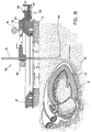
- FIG. 8 illustrates a heart manipulator 64 for use in conjunction with surgical retractor 10 and for mounting on base 12.
- Heart manipulator 64 includes loop shaped frame 66 that supports mesh surface 68.
- Frame 66 and mesh surface 68 together form a heart contacting surface for manipulating the heart therewith.
- frame 66 includes upright portion 70, generally horizontally extending portion 72 and atraumatic curved end portion 74, which provide a surface for engaging and manipulating the heart.
- Frame 66 is supported by mounting bar 76 which is slidably received in support bracket 78 for height adjustment.
- Set screw 80 secures mounting bar 76 with respect to support bracket 78.
- support bracket 78 and heart manipulator 64 Radial positioning of support bracket 78 and heart manipulator 64 is achieved by slidable mounting of support bracket 78 on mounting assembly 82 which mounts to base 12 in a manner substantially similar to that of mounting assembly 16 described above with respect to FIG. 3-4.
- Set screw 84 secures the radial position of heart manipulator 64 with respect to mounting assembly 82.
- support bracket 78 has an elongated slot 79 formed therein which enables bracket 78 to slide radially with respect to set screw 84 and mounting assembly 82.
- mounting assembly 82 like mounting assembly 16, has a mounting bracket 83 which engages inner lip 30 of base 12, retainer block 81, and retainer spring 87. Handle 89 of retainer block 81 enables the engagement and disengagement of mounting assembly 82 in the same manner as mounting assembly 16 described above.
- FIG. 9 a heart manipulator 90 is shown in accordance with another preferred embodiment.
- Loop frame 66 and mounting assembly 82 are substantially as described above with respect to heart manipulator 64 in FIG. 8.
- Mounting bar 92 supports frame 66 and has a substantially right angled bend 94 for slidable insertion in support bracket 96.
- Radial position of heart manipulator 90 is achieved by sliding mounting bar 92 with respect to support bracket 96 and secured thereto by set screw 98.
- height adjustment of heart manipulator 90 is not provided, access to the operative site is enhanced by the one-piece design of mounting bar 92.
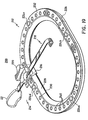
- FIG. 10 illustrates a heart stabilizer instrument 100, configured to apply pressure to the coronary artery to reduce blood flow in the artery to allow anastomosis to the coronary artery and to reduce movement of the heart muscle between legs 104a, 104b in order to enable the surgeon to perform cardiovascular surgery.
- Heart stabilizer instrument 100 is mounted to base 12 by mounting assembly 82, substantially as described above.
- Heart stabilizer instrument 100 includes frame 102 supporting legs 104a and 104b and transverse bars 106a and 106b.
- Protrusion 108a is formed on transverse bar 106a
- protrusion 108b is formed on transverse bar 106b.
- Protrusions 108a and 108b have an atraumatic convex heart contacting surface and permit the exertion of localized pressure on the coronary artery when frame 102 is compressed on the surface of the heart.
- Mounting bar 110 is slidably received in support bracket 78 and secured with respect thereto by set screw 80. Radial positioning of heart stabilizer instrument 100 with respect to mounting assembly 82 is secured by a coupling means, such as set screw 84.
- FIG. 11 the operation of the surgical retractor 10 will now be described.
- Conventional surgical techniques are used to determine the location of the incision I accessing the chest cavity C.
- Base 12 is placed on the chest of the patient with the opening overlying the operative site.
- Incision I is made, exposing several ribs R 1 , R 2 , and R 3 .
- retractor assemblies 14a, 14b, and 14c are mounted to base 12 at various locations.
- Hook 20a is positioned around a rib R 1 .
- Assist strap 22a is used to provide a grip for the surgeon to deflect and retract rib R 1 by pulling retractor blade 18 radially outward.
- One way ratchet assembly 23a maintains retractor blade 18 and consequently rib R 1 in position.
- Rib R 2 is retracted in a substantially identical manner by hook 20b on retractor assembly 14b. Additional retractors are mounted and used to retract ribs until a sufficiently large opening O in chest cavity C is defined in order to provide access to the heart.
- retractors can be mounted anywhere along base 12 in order to perform their function.
- the sternum and the fourth and fifth ribs can be spread apart to create a window.
- the fourth and fifth ribs are cut from the sternum and spread to create a larger window.
- a fifth rib can be cut, and the sternum and the fourth and sixth ribs are spread.
- Base 12 is at least partially held in position over the operative site by tension created in retracting the ribs by retractor blades 18.
- Internal tissue structures may be tied down utilizing sutures passing through securement points 24a, 24b, 24c and 24d.
- heart manipulator 64 is mounted to base 12 in order to manipulate the position of heart H to facilitate the surgery.
- heart manipulator 64 is positioned in the chest cavity adjacent heart H.
- Frame 66 and mounting bar 76 can be lowered and fixed by set screw 80 such that horizontal portion 72 and curved end portion 74 are positioned slightly underneath heart H.
- heart manipulator 64 is displaced radially inward and against heart H by loosening set screw 84 and sliding mounting bar 92 in the direction of the arrow.
- set screw 84 When sufficient pressure is placed on the heart to substantially fix its position, heart manipulator 64 is secured by the tightening of set screw 84.
- FIG. 16 illustrates the mounting of heart stabilizer instrument 100 to base 12.
- heart stabilizer instrument 100 is positioned over heart H and more particularly, over coronary artery A.
- the radial positioning of instrument 100 is accomplished by relative movement of support bracket 78 with respect to mounting assembly 82.
- frame 102 and mounting bar 110 are lowered with respect to support bracket 78 such that frame 102 applies direct pressure on heart H.
- Protrusions 108a and 108b localize this pressure to substantially restrict the flow of blood from coronary artery A and 104a and 104b reduce movement of the surface of the heart muscle to facilitate the surgery.
- Heart movement is restricted by virtue of the leg pressure and the anti-slip texture of the legs 104a and 104b.
- the position of instrument 100 may be locked with respect to the base as set forth in detail below.
- FIGS. 19-33 another preferred embodiment of the surgical retractor is disclosed at reference numeral 200.
- Instrument 200 operates substantially as described above with regard to instrument 10, with the differences described hereinbelow.
- FIG. 19 illustrates surgical retractor 200 having base 212 and retractor blade assembly 214, which includes mounting bracket 216, retractor blade 218 and retraction knob 220.
- the provision of retraction knob 220 enables the surgeon to achieve additional mechanical advantage in retracting a rib.
- Base 212 includes suture mounting portions 224a, 224b, 224c and 224d for securing base 212 adjacent the surgical site.
- Base 212 further includes beveled inner surface 228 with inner lip 230 and top surface 232 in which a series of cylindrical recesses or openings 240 are defined.
- mounting bracket 216 includes sleeve 242 defining open-sided channel 244 for sliding reception of retractor blade 218.
- Pawl member 246 has a series of ratchet teeth 248 configured to engage ratchet teeth 258 on retractor blade 218 when blade 218 is slidably inserted in channel 244.
- Retraction knob 220 is rotatably positioned in aperture 236 in mounting bracket 216. With reference to FIG. 20 in conjunction with FIG. 21, retraction knob 220 includes pinion gear 260 which cooperates with rack 262 provided on retractor blade 218. As will be described below, rotation of knob 220 provides additional mechanical advantage in cooperation with one-way ratchet mechanism 23 to retract and/or advance retractor blade 218.
- retractor blade assembly 214 is mounted to base 212 in a simple, one-handed motion.
- Mounting bracket 216 includes pin 264 on a bottom portion thereof dimensioned to be received in one of cylindrical recesses 240 in base portion 212. The length of pin 264 is preferably substantially equivalent to the depth of recess 240 to provide stability to mounting bracket 216.
- wedge shaped inner portion 266 of mounting bracket 216 cooperates with beveled inner surface 228 of base 212 to facilitate positioning and to provide resistance against tilting of retractor blade 218.
- Mounting bracket 216 is further secured in position by tab 270 which includes a flange 272 which engages outer rim 274 of base 212. As illustrated in FIG. 23, removal and placement of mounting bracket 216 is accomplished by deflecting flange 272 of tab 270 clear of outer rim 274.
- Tab 220 includes rigid lever arm 276 which facilitates such deflection of tab 270.
- assist straps 22 See, FIG. 19
- Retracting blade 218 is displaced radially outwardly as far as possible given the strength of the surgeon.
- additional retraction force can be applied to the rib by rotation of retraction knob 220.
- Pinion gear 260 disposed on knob 220 engages rack 262 on retraction blade 218 and provides additional leverage to the surgeon. As illustrated in FIG. 25, pawl 246 is normally biased against retraction blade 218 such that ratchet teeth 258 on blade 218 and ratchet teeth 248 on pawl 246 engage to prevent radially inward movement. It should be appreciated that knob 220 is optionally removable so it can be used to retract each retractor blade 218.
- FIG. 26 illustrates that pawl 246 may be rotated away from retraction blade 218 by pivoting lever 262 to disengage teeth 258 and 248. Unrestricted radial movement of retraction blade 218 is facilitated thereby.
- FIGS. 27-28 illustrated another embodiment of a heart manipulator instrument designated by reference numeral 300.
- Heart manipulator 300 is used to manipulate the position of the heart and operates substantially as described above with regard to heart manipulator 64, with the differences described below.
- heart manipulator 300 includes frame member 302, formed in a modified "U" configuration having an upright portion wherein the bars are parallel, including closely spaced mounting portions 304a and 304b, more widely spaced mesh supporting portions 306a and 306b, and a curved horizontally extending portion 308.
- Mesh supporting portions 306a and 306b and horizontally extending portion 308 support a mesh surface 310 therebetween.
- Mounting portions 304a and 304b are snap fit within bores formed in support bracket 320.
- members 304a and 304b may be slidable with respect to bracket 320 and secured with set screws (not shown). Radial positioning of support bracket 320 is achieved by slidable mounting of support bracket 320 on mounting bracket 322. Set screw 324 is used to secure the radial positioning of heart manipulator 300. Elongated slot 330 allows movement of support bracket 320 with respect to set screw 324 and mounting bracket 322.
- mounting bracket 322 is configured to mount on base 212 substantially as described with respect to mounting bracket 216 in FIGS. 22-23.
- Pin 364 of bracket 322 is received in one of openings 240 in base 212.
- Tab 370 includes flange 372 which removably engages outer rim 274 of base 212 and is disengaged by lever arm 376.
- Support bracket 320 is slidably mounted on mounting bracket 322 such that a portion of slot 330 is aligned over threaded bore 332.
- Set screw 324 extends through slot 330 into bore 332 and includes collar 334 which abuts a top surface of support bracket 320 to secure it against radial movement.
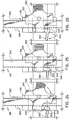
- FIGS. 29-32 illustrate a heart stabilizer instrument 350 in accordance with another preferred embodiment of the subject disclosure.
- heart stabilizer instrument 350 includes frame 102 and mounting bar 110.
- Frame 102 includes legs 104a and 104b and transverse bars 106a and 106b having protrusions 108a and 108b substantially as described with respect to FIG. 10, above.
- Mounting bar 110 is slidably received in a bore in support bracket 352 and secured with respect thereto by set screw 354.
- Support bracket 352 is slidable with respect to mounting bracket 356.
- mounting bracket 356 is removably mounted on base portion 212 substantially as described with respect to mounting bracket 216 in FIGS. 22-23.
- Pin 358 is received in one of cylindrical recesses or openings 240 in base 212.
- Tab 360 includes flange 362 for removably engaging outer rim 274 of bore 212. Flange 362 is disengaged by actuation of lever arm 364.
- support bracket 352 includes a pair of vertical walls 364a and 364b and a pair of horizontal walls 366a and 366b which rest on a top surface of mounting bracket 356.
- a lever mounting rod 368 extends upwardly from mounting bracket 356 between horizontal walls 366a and 366b.
- a pair of hinge pins 370a and 370b extend from rod 368 and are received in a clevis portion 372 of lever arm 374.
- Horizontal walls 366a, 366b of support bracket 352 are disposed between mounting bracket 356 and clevis portion 372 of lever arm 374.
- clevis portion 372 is substantially circular or elliptical in lateral cross-section and is eccentrically mounted to hinge pins 370a and 370b. As illustrated in FIG. 30, when lever arm 374 is in a released position, clevis portion 372 is spaced from horizontal walls 366a and 366b and unrestricted radial movement of support bracket 352 is enabled thereby. As illustrated in FIG. 31, pivoting of lever arm 374 causes clevis portion 372 to apply a compressive force on horizontal walls 366a and 366b on top of mounting bracket 356 to thereby fix the radial position of support bracket 352 with respect to mounting bracket 356.
- FIG. 33 operation of surgical retractor 200 in conjunction with heart manipulator and heart stabilizer instrument proceeds substantially as described with respect to FIGS. 11-18.
- mounting bracket 216a of retractor blade assembly 214 is placed on base 212 by actuation of lever arm 276a (not shown).
- Heart manipulator 200 and heart stabilizer instrument 350 are mounted to base 212 in a substantially identical manner as described above.
- the surgical procedure is carried out substantially as described above.
- Ribs R 1 , R 2 and R 3 are retracted by the pulling of assist straps 22 and by the rotation of retraction knob 220.
- the position of heart H is stabilized by heart manipulator 300.
- Heart stabilizer instrument 350 is positioned and lowered onto heart H to apply pressure to the coronary artery and thereby substantially reduce movement (motion) of the heart within the legs.
- the instrument 350 may be locked with respect to the base. At this time, other surgical procedures, such as coronary bypass or valve surgery may be performed.
- FIGS. 34-52 another embodiment of the surgical retractor is disclosed at reference numeral 400.
- Instrument 400 operates substantially as described with regard to instrument 200, with the differences noted hereinbelow.
- FIG. 34 illustrates surgical retractor 400 having base 412 and retractor blade assembly 414, which includes mounting bracket 416, retractor blade 418, and retraction knob 420.
- the provision of retraction knob 420 enables the surgeon to achieve additional mechanical advantage in retracting a rib.
- Base 412 includes suture mounting portions 424 for suture tie down of internal tissue structures.
- Base 412 further includes beveled inner surface 428 with inner lip or rim 430 and top surface 432, which forms an outer lip or rim 434.
- a channel or groove 436 is formed in top surface 432.
- Outer periphery 438 of base 412 includes a series of teeth 440 formed thereon.
- mounting bracket 416 includes housing 442 and mounting plate 444 which are connected and allow retractor blade 418 to slide within channel 446 defined in a lower surface of housing 442.
- Retractor blade 418 includes body portion 448 and rib engaging portion 450.
- Body portion 448 defines a T handle 452 configured to be grasped by the surgeon in order to slide retractor blade 418 within channel 446.
- Body portion 448 defines a rack gearing 454 and a series of sloping ratchet teeth 456.
- gearing 454 and ratchet teeth 456 are respectively disposed along elongated channel 458 defined within body portion 448.
- Ratchet teeth 456 are releasably engaged by pawl 460.
- Mounting plate 444 defines first channel 462 and second channel 464 for receiving pawl 460.
- pawl 460 is a resilient member having a modified U-shaped configuration including crown portion 466, first leg 468 defining cut-out portion 470, and second leg 472.
- Second leg 472 is fixedly retained within second channel 464 having an elbow configuration.
- the junction of second leg 472 and crown 466 acts as a hinge or pivot such that first leg 468 is slidable within first channel 462.
- Pawl 460 is normally biased at this junction of second leg 472 and crown 466 such that first leg 468 is partially disposed in first channel 462.
- Crown 466 may be pressed by the user towards mounting plate 444 against the normal bias to slide first leg 468 further along first channel 462.
- Retractor blade 418 is positioned adjacent mounting plate 444, and pawl 460 is placed on top of blade 418 such that cut-out portion 470 of first leg 468 straddles a portion of blade 418 adjacent ratchet teeth 456. (See, FIG. 38)
- pawl 460 is normally biased such that first leg 468 is in engagement with one of ratchet teeth 456.
- Pawl 460 and ratchet teeth 456 together define a one-way ratchet mechanism 474.
- Rack gearing 454 is engaged by pinion gearing 476 formed on retraction knob 420, which is positioned in aperture 478 defined in housing 442. As will be described below, rotation of retraction knob 420 provides additional mechanical advantage when used in cooperation with ratchet mechanism 474 to retract and/or advance retractor blade 418.
- Rib engaging portion 450 is connected to body portion 448 with a dovetail joint and secured thereto with pins 480a and 480b.
- retractor blade 418 may be constructed of a single part.
- Rib engaging portion 450 includes a horizontal portion 482, angularly depending portion 484, and tip portion 486.
- Angularly depending portion 484 forms an acute angle with horizontal portion 482 to securely engage the rib.
- Strengthening rib or beading 488 is formed on the outside of rib engaging portion 450 to provide additional strength and to resist bending.
- mounting plate 444 includes a gearing 490 on a forward portion thereof to engage peripheral gear teeth 440 on base 412 (See, FIG. 34).
- base 412 is placed at the operative site on patient's chest.
- Rib engaging portion 450 is positioned adjacent rib R, such that angularly depending portion 484 and tip portion 486 at least partially surround rib R.
- Housing 442 has a flat bottom portion and is placed on upper surface 432 of base 412.
- FIG. 37 illustrates the simultaneous mounting of mounting bracket 416 to base 412 and retraction of rib R towards base 412 as indicated by the arrows.
- Retractor blade 418 is moved radially outward with respect to base 412 while rib engaging portion 450 engages rib R.
- Mounting plate 444 is spaced from the bottom portion of housing 442 in order to permit mounting plate 444 to slide under outer rim 434 of base 412, and to allow teeth 490 engage teeth 440 on base 412.
- Mounting bracket 416 is secured on base 412 by the compression force created between rib engaging portion 450 against rib R and mounting plate 444 against outer rim 434 of base 412. Removal of retractor blade 418 from rib R occurs by sliding retractor blade 418 radially inward, thereby releasing compression sufficiently to allow mounting plate 444 to be released from outer rim 434.
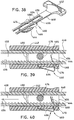
- One-way ratchet mechanism 474 enables retractor blade 418 to be incrementally moved in one direction, i.e. radially outwardly to retract a rib, while resisting movement in an opposite direction, i.e. radially inward.
- FIG. 38 illustrates pawl 460 normally biased such that first leg 456 is in engagement with ratchet teeth 456.
- sloping portions 490 of teeth 456 permit retractor blade 418 to incrementally move in a radially outward motion while transverse slopes 492 of teeth 456 inhibit radially inward motion to hold retractor blade 418 and the rib in position.
- additional retraction force can be applied to the rib by rotation of retraction knob 420.
- Pinion gear 476 disposed on retraction knob 420 engages rack 454 on retraction blade 418 to provide additional leverage to the surgeon.
- rotation knob 420 may be removed from aperture 478 in housing 442 (See, FIG. 35) and thereby provide greater visibility and access for the surgeon.
- Pawl 460 may be moved against its normal bias by depressing crown 466 towards mounting plate 444, which causes first leg 468 to disengage from ratchet teeth 456 as shown in FIG. 40. Cut-out portion 470 as aligned such that blade 418 may slide therethrough, such that unrestricted radial movement of retraction blade 418 is enabled.
- FIGS. 41-49 illustrate a heart stabilizer instrument 500 in accordance with another preferred embodiment of the subject disclosure.
- heart stabilizer instrument 500 includes frame 502, articulating arm 504, and mounting assembly 506.
- Articulating arm 504 is configured to allow frame 502 to be positioned at the precise location and orientation with respect to the heart of the patient.
- Mounting assembly 506 secures articulating arm 504 and frame 502 in a fixed configuration, as will be described below.
- Frame 502 is configured to contact the heart and applies pressure to the heart without touching the coronary artery.
- Frame 502 includes a pair of legs 508a and 508b, each having teeth 510 for atraumatically contacting the heart.
- Frame 502 is mounted to frame mount 512 by pin 514.
- the distal end of cable 516 is mounted to frame 502, and passes into frame mount 512 at opening 513.
- Articulation arm 504 consists of a plurality of link members 518a, 518b, 518c, 518d, each of which has hemispherical convex distal portion 520, cylindrical body portion 522 including peripheral step 523, and concave proximal end 524.
- Bore 526 extends longitudinally through each link 518 from convex distal portion 520 to concave proximal end 524.
- Link members 518 are aligned such that convex distal portion 520 is received in concave proximal end 524 in a ball-and-socket type connection to permit a wide range of pivoting motion between adjoining link members 518.
- Link members 518 are concatenated by cable 516 passing through each bore 526, and the distalmost link member 518a is fitted adjacent frame mount 512.
- Articulation arm 504 can be used to mount a light cable to illuminate the surgical site, a suction and/or irrigation device, a blowing device to disperse blood or any other instrument to facilitate the surgery.
- Mounting assembly 506 is mounted adjacent proximalmost link member 518d and includes mounting flange member 530, mounting base 532, toggle housing 534, and toggle 536.
- mounting base 532 has a flat bottom surface 538 to rest on top surface 432 of base 412 and a protrusion or peg 540 configured and dimensioned to be received in flange 436 of base 412.
- mounting flange member 530 and toggle housing 534 are slidably mounted with respect to mounting base 532 and are normally biased in a spaced-apart configuration from mounting base 532 by springs 542 and 544, respectively.
- Mounting flange member 530 has flange 546 for engaging inner rim 430 of base 412.
- Toggle housing 534 has flange 548 for engaging outer rim 434 of base 412.
- Toggle 536 includes cylindrical mounting portion 550 and toggle arm 552.
- Cylindrical mounting portion 550 is configured to be received within cylindrical recess 554 defined within toggle housing 534 and to be pivotably movable therein.
- Cable 516 extends through link members 518 and through mounting flange member 530, spring 542, mounting base 532, spring 544, and into cylindrical recess 554 of toggle housing 534. The distal end portion of cable 516 is pinned to toggle 536 by pin 556.
- cylindrical mounting portion 550 defines a laterally offset pie-shaped or arc-section recess 558 to define an "over-center" type locking mechanism, as will be described below.
- heart stabilizer instrument 500 is configured such that cable 516 extends through instrument 500 from frame 502 to toggle 536.
- Bore 526 in each link member 518 has a tapering diameter which is larger adjacent convex distal portion 520 and is narrower adjacent concave proximal portion 524. This configuration permits relative articulation of link members 518 while cable 516 extends therethrough.
- FIGS. 44-46 illustrate heart stabilizer instrument 500 with cable 516 in a relaxed unstressed configuration.
- instrument 500 is placed on base 412 such that peg 540 is disposed in groove 436, and mounting flange member 530 and toggle housing 534 are spaced apart sufficiently to allow flanges 546 and 548 to clear inner rim 430 and outer rim 434, respectively.
- toggle 536 is disposed in toggle housing 534 in an unlocked configuration, such that toggle arm 552 and fixed arm 535 are spaced apart.
- Eccentrically mounted pin 556 is disposed such that cable 516 is loose.
- FIG. 46 illustrates that cable 516 loosely disposed in tapered bores 526 of link member 518 permit articulation of adjoining link members 518.
- FIGS. 47-49 illustrate instrument 500 with cable 516 in a taut, stressed configuration.
- toggle 536 is pivoted with respect to toggle housing 534 such that toggle arm 552 is approximated with fixed arm 535.
- the distal end of cable 516 connected to pin 556 moved into an "over-center” position, thereby stressing cable 516 and locking surgical instrument 500 in position. The surgeon is permitted to perform other procedures without maintaining pressure on the heart.
- FIG. 50 Another embodiment of the heart stabilizer instrument is illustrated in FIG. 50 and disclosed at reference numeral 600.
- Instrument 600 is constructed and operates substantially as described above with regard to instrument 500, with the differences described below.
- Heart stabilizer instrument 600 includes frame 502, articulating arm 606 and mounting assembly 506.
- Articulating arm 606 permits frame 502 to be placed at the appropriate height and angle with respect to the heart.
- Articulating arm 606 is composed of link members 608, and 610 having a series of intermeshing teething to positively engage adjoining link members together.
- link members 608 are positioned adjacent link member 610.
- Link member 608 has generally cylindrical body portion 612.
- a pair of rows of concave gearing 614a and 614b is disposed on one axial end 616 of link member 608.
- a second pair of rows of concave gearing 618a and 618b is disposed on the second axial end 620 of link member 608.
- Gearing 614a and 614b is disposed 90 o out of alignment with gearing 616a and 616b.
- Longitudinal bore 622 extends through link member 608 from axial end 616 to axial end 620 between each pair of gearing.
- Link member 610 has body portion 624, to which first pair of gearing 626a and 626b having a convex profile and second pair of convex gearing 628a and 628b are attached to opposite sides thereof. First pair of gearing 626a and 626b is disposed 90 o out of alignment with second pair of gearing 628a and 628b.
- a longitudinal bore (not shown) extends through body portion 624 and between each pair of gearing 626a and 626b and gearing 628a and 628b.
- Link member 610 is placed adjacent link member 608. Cable 516 extends through longitudinal bore 622 in link member 608 and longitudinal bore (not shown ) in link member 610. When toggle 552 is moved to the "over center” position (See, FIG. 47), thereby tightening cable 516, link members 608 and 610 are approximated such that convex gearing 626a, 626b or 628a, 628b of link member 610 engages concave gearing 614a, 614b and 618a, 618b of link member 608.
- FIG. 51 illustrates another preferred embodiment of the surgical retractor in accordance with the subject disclosure.
- This surgical retractor designated generally at 700, includes a base 702 and any one or more of the instruments shown including: retractor blade assembly 704; retractor blade assembly with suction/irrigation structure 706; retractor blade assembly with light 708; heart manipulator 710; and heart stabilizer instrument 712. These instruments are discussed in greater detail hereinbelow.
- Base 702 is configured in accordance with the other bases discussed above and provides a low profile mount for instrumentation used in the surgical procedure being performed.
- a plurality of suture mounts 714 are defined in an upper peripheral portion 716 of base 702 and serve as attachment and anchor points for suture ends 718 from the surgical field.
- suture mounts 714 include a tightly wound coil spring 720 positioned in a cavity 722 with the coils oriented substantially transverse to the radians of the base 702.
- a triangular ramp 724 is formed on an inner radial surface of suture mount 714.
- a slot 726 is formed on an outer radial surface of suture mount 714 beyond coil spring 720 and in axial alignment with ramp 724. This ramp/slot configuration facilitates easy access to position suture end 718 in coil spring 720.
- base 702 is configured in substantially the same manner as previously described bases and includes teeth 728, beveled inner peripheral surface 730 and inner lip 732.
- Surgical retractor blade assembly with blowing structure 706 is shown in FIGS. 54-56.
- structure 706 can also be used for suction or for irrigation to remove fluids from the surgical site.
- the retractor blade assembly 704 is similar to the retractor blade assembly 414 discussed in detail above.
- Retractor blade assembly 704 includes mounting bracket 734, retractor blade 736 and removable retraction knob 738.
- mounting bracket 734 includes housing 740 and mounting plate 742 which together form a channel through which retractor blade 736 is reciprocally slidable.
- Retractor blade 736 includes body portion 744 and rib engaging portion 746.
- Body portion 744 defines a flanged gripping handle 748 configured to be grasped by the surgeon in order to slide retractor blade 736 relative to mounting bracket 734.
- Body portion 744 further defines longitudinally oriented rack gearing 750 and a series of sloping teeth 752.
- Rack gearing 750 and teeth 752 are disposed along elongated cavity 754 defined in body portion 744.
- Teeth 752 are releasably engaged by pawl 756 mounted in housing 740. Operation of this pawl 756 is substantially the same as pawl 460 described above in connection with retractor blade assembly 414.
- Rib engaging portion 746 extends distally from body portion 744 and includes an angularly depending portion including one or more strengthening ribs 758 to provide additional strength.
- Blowing structure 760 is integrally formed into the retractor blade assembly shown in FIGS. 54-56.
- This structure includes a tube 762 which extends the length of the retractor blade assembly and exits the ring engaging portion 764 to access the surgical site.
- a tube connector 764 is positioned at a proximal end of tube 762 and connects to an appropriate source such as a vacuum or pressure source (not shown) depending on whether structure 760 is used for blowing, irrigation or suction.
- Forming wire 766 is positioned adjacent tube 762 and is deformable to configure tube 762 in a desired angular orientation. Alternatively, tube 762 may be remotely oriented or rotated from body portion 744 using known structure.
- FIGS. 57 and 58 illustrate a retractor blade assembly with an integral light shown generally at 708.
- the basic configuration and operation of this assembly is identical to that described above with the difference that a light 768 has been substituted for suction/irrigation structure.
- a wide variety of lights can be accommodated.
- a fiber optic bundle is disposed within a longitudinally extending sheath 770.
- a fiber optic coupler 772 is positioned adjacent the proximal end of the assembly and can be connected to an appropriate light source (not shown). It is also envisioned that a wide variety of divergent and focusing lenses may be used to tailor the light as required by the surgeon.
- FIGS. 58A-C The one-way ratchet mechanism used in these embodiments of the retractor blade assembly is shown in FIGS. 58A-C.
- This ratchet mechanism operates in the same manner as the ratchet mechanism discussed above with respect to FIGS. 39-40.
- the retractor blade 736 can be pulled in the direction of the arrow to retract the bone and tissue.
- pawl 756 must be pressed in.
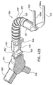
- FIGS. 59-63 illustrate another embodiment of a heart stabilizer instrument 800 in accordance with the subject disclosure.
- Heart stabilizer instrument 800 is similar to heart stabilizer instrument 500 discussed in detail above.
- the instrument includes frame 802, articulating arm 804 and mounting assembly 806.
- Frame 802 is configured in the same manner as frame 502 and includes a pair of legs 808a and 808b, each having teeth 810 for atraumatically contacting the surface of the heart.
- Frame 802 is connected to articulating arm 804 by connector 812.
- a positioning flange 814 is formed on connector 812 and facilitates positioning of frame 802 on the heart surface either by manually grasping the flange 814 or by affixing a grasping instrument (not shown) to the flange 814 and positioning the frame in a desired location.
- Mounting assembly 806 is mounted adjacent the articulating arm 804 and includes mounting flange member 830, mounting base 832, toggle housing 834, and toggle 836. As shown in FIGS. 61-62, mounting base 832 has a flat bottom surface 838 to rest on the top of base 702. Mounting flange member 830 and toggle housing 834 are slidably mounted with respect to mounting base 832. Mounting flange member 830 has flange 846 for engaging inner rim of base 702. Toggle housing 834 has flange 848 for engaging outer rim of base 702.
- Toggle 836 includes cylindrical mounting pins 850 and finger loop 852. Cylindrical mounting pins 850 are configured to be received within recess 854 defined within toggle housing 834 and to be pivotably movable therein. Cable 816 extends through articulating arm 804. The distal end portion of cable 816 is pinned to toggle 836 by clip 856. Biasing spring 858 is positioned in toggle housing 834 and serves to normally bias mounting flange member 830 distally relative to toggle housing 834.
- Handle spring member 860 is integrally formed on toggle 836 and is configured to operatively interact with protrusion 862 formed in cavity 854 of toggle housing 834, as toggle 836 is moved into and out of approximation with toggle housing 834.
- FIGS. 64-66 illustrate heart stabilizer instrument 800 with cable 816 in an unlocked, unstressed configuration.
- instrument 800 is placed on base 702 with mounting flange member 830 and toggle housing 834 spaced apart sufficiently to allow flanges 846 and 848 to clear inner rim 830 and outer rim 833, respectively.
- Toggle 836 is disposed in toggle housing 834 in an unlocked configuration, such that finger loop 852 and finger loop 853 are spaced apart. Cable 816 is loose to permit manipulation of articulating arm 804.
- FIG. 65 illustrates the relative position of handle spring 860 relative to protrusion 862 within toggle housing 834.
- FIGS. 66-67 illustrate instrument 800 with cable 816 in a first taut, locked, unstressed configuration.
- toggle 836 is pivoted with respect to toggle housing 834 such that finger loop 852 is moved toward finger loop 853.
- the distal end of cable 816 is stressed to approximate mounting flange member 832 and mounting base 832 locking surgical instrument 500 in position on base 702.
- FIG. 67 shows the progression of toggle 836 relative to toggle housing 834 into the locked, unstressed configuration. In this position, articulating arm 804 can still be manipulated.
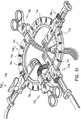
- FIGS. 68-69 The final, locked and stressed configuration is shown in FIGS. 68-69.
- finger loops 852 and 853 have moved into close approximation simultaneously, further stressing cable 816 to maintain a preset configuration desired by the surgeon, e.g. to lock articulating arm 804 in place.
- the surgeon is permitted to perform other procedures without having to manually apply pressure on the heart via the heart stabilizer instrument.
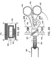
- FIG. 70 Another preferred embodiment of the heart manipulator 900 in accordance with the subject disclosure is shown in FIG. 70.
- the heart manipulator includes a manipulator portion 902, an articulating arm 904 and a mounting assembly 906.
- the structure and operation of mounting assembly 906 and articulating arm 904 are substantially the same as the heart stabilizer 800 discussed above.
- the manipulator portion 902 includes a frame 908 supporting mesh 910 and is preferably provided with a curved section adjacent a distal end thereof to assist in manipulation of the heart.
- FIGS. 71A and 71B illustrate a rib elevator 980 which can be mounted to the aforedescribed bases to enable the patient's rib to be lifted.
- Rib elevator 980 includes a set of tabs 982 which engage inner lip 732 for attachment to the base.
- Reinforcement ribs 984a, 984b formed on the rear surface 981 increase the rigidity of rib elevator 980 and also provide a gripping surface for the user to flex the rib elevator 980 to facilitate attachment and removal from the base.
- Teeth 986 function in the same manner as the teeth 728 of base 702, i.e. for mounting one or more of retractor assemblies 704, 706, 708.
- rib elevator 980 when rib elevator 980 is mounted to base 702, the mounted retractor assembly will be angled towards the rib so that a retraction force will be applied to the rib partially in an upward direction. This is advantageous, for example, for access and severing of the IMA.
- the rib elevator 980 can subsequently be removed and a retractor assembly mounted directly to the base 702 in the manner described above.
- FIGS. 72 and 73 illustrate two preferred kit configurations in accordance with the subject disclosure.
- Kit 950 (FIG. 72) is formed to accommodate a basic blade retractor assembly 704, a blade retractor assembly with suction irrigation 706, a blade retractor assembly with light 708, a base 702, a retraction knob 738, a heart stabilizer instrument 800 and/or a heart manipulator 900 therein.
- Cavities 952, 954, 956, 958 and 960 are formed in cover 962 to accommodate these elements.
- Cover 962 may be fixed to bottom 964 by adhesive, ultrasonic welding, heating, etc.
- Kit 970 is substantially similar to kit 950 except that the heart stabilizer instrument 800 and the heart manipulator 900 are excluded.
- Cover 972 includes cavities 952, 958 and 960 to accommodate retractors 704, 706, 708, base 702 and retraction knob 738.
- Cover 972 and bottom 974 may be joined in the same manner as disclosed for kit 950 above.
- Rib elevator 980 can optionally be included in the kits.
Landscapes
- Health & Medical Sciences (AREA)
- Life Sciences & Earth Sciences (AREA)
- Surgery (AREA)
- Heart & Thoracic Surgery (AREA)
- Engineering & Computer Science (AREA)
- Biomedical Technology (AREA)
- Nuclear Medicine, Radiotherapy & Molecular Imaging (AREA)
- Medical Informatics (AREA)
- Molecular Biology (AREA)
- Animal Behavior & Ethology (AREA)
- General Health & Medical Sciences (AREA)
- Public Health (AREA)
- Veterinary Medicine (AREA)
- Surgical Instruments (AREA)
Abstract
Description
- The subject disclosure relates to minimally invasive surgical procedures and apparatus, and more particularly to an instrument and method for performing surgery associated with the thoracic cavity.
- The diagnosis and treatment of coronary disease and related conditions typically requires access to the heart, blood vessels and associated tissue. Such procedures include cardiopulmonary bypass, valve repair and replacement, and treatment of aneurysms. Access to the patient's thoracic cavity may be achieved by a large longitudinal incision in the chest. This procedure, referred to as a median sternotomy, requires a saw or other cutting instrument to cut the sternum and allow two opposing halves of the rib cages to be spread apart. U.S. Patent No. 5,025,779 to Bugge discloses a retractor which is designed to grip opposite sternum halves and spread the thoracic cavity apart. The large opening which is created by this technique enables the surgeon to directly visualize the surgical site and perform procedures on the affected organs. However, such procedures that involve large incisions and substantial displacement of the rib cage are often traumatic to the patient with significant attendant risks. The recovery period may be extended and is often painful. Furthermore, patients for whom coronary surgery is indicated may need to forego such surgery due to the risks involved with gaining access to the heart.
- U.S. Patent No. 5,503,617 to Jako discloses a retractor configured to be held by the surgeon for use in vascular or cardiac surgery to retract and hold ribs apart to allow access to the heart or a lung through an operating window. The retractor includes a rigid frame and a translation frame slidably connected to the rigid frame. Lower and upper blades are rotatably mounted to the rigid frame and the translation frame respectively.
- Once access to the thoracic cavity has been achieved, surgery on the heart may be performed. Such procedures typically require that the heart beat be arrested while maintaining circulation throughout the rest of the body. Cardioplegic fluid, such as potassium chloride (KCl) is delivered to the blood vessels of the heart to paralyze the myocardium. As disclosed in WO 95/15715 to Sterman et al. for example, cardioplegic fluid is infused into the myocardium through the coronary arteries by a catheter inserted into the ascending aorta. Alternatively, cardioplegic fluid is infused through the coronary veins in a retrograde manner by a catheter positioned in the interior jugular vein accessed at the patient's neck. Such procedures require the introduction of multiple catheters into the blood vessels adjacent the heart, which is a complicated procedure requiring that the desired vessels be properly located and accessed. The progression of the guide wires and catheters must be closely monitored to determine proper placement. Furthermore, the introduction of catheters forms punctures in the blood vessels that must be subsequently closed, and there is an increased risk of trauma to the interior walls of the vessels in which the catheters must pass.
- Therefore, a need exists for an apparatus and procedure which provides access to the thoracic cavity without causing extensive trauma to the patient. A procedure is needed to at least locally stabilize a predetermined area of the heart surface that is relatively simple to perform and incorporates instruments that are simple and reliable. Furthermore, an apparatus and procedure is needed which provides a stable framework for supporting additional instruments which may be used during these procedures.
- The present disclosure is directed to instruments for and methods of surgery. A retractor is provided which has a substantially planar base defining an opening for overlying an operative site on a patient, and at least one retractor blade slidably mounted to the base.
- The base is positioned on the patient such that the opening therein overlies the operative site, and the operative site is percutaneously accessed through the opening. Obstructing tissue is retracted with one or more retractor blades to create an opening to provide access for the surgical procedure. A surgical instrument is provided which is engageable with the base and operable at the operative site. A surgical procedure is carried out through the opening in the base with the surgical instrument.
- In a preferred embodiment, the retractor blade includes a ratchet assembly, and the method includes fixing the position of the retractor blade with respect to the base with the ratchet assembly.
- The retractor blade may also include an integral blowing, irrigation or suction assembly operably positioned adjacent the blade to remove blood, fluid, etc. In another embodiment, a light assembly may be incorporated to illuminate designated portions of the surgical field.
- A heart manipulator is disclosed for use in conjunction with the retractor and is releasably mountable on the base. The heart manipulator assists in atraumatically holding and positioning the heart to facilitate access thereto. In a preferred embodiment the heart manipulator includes a loop shaped frame which supports a mesh cradle.
- A heart stabilizer instrument is also disclosed. This instrument is preferably configured to be mounted to the base portion and has a heart contacting surface. The heart may be contacted with the heart contacting surface to stabilize the position of a predetermined portion of the heart surface. A heart stabilizer instrument may be provided which is mounted to the base portion and movable with respect thereto. The predetermined portion of the heart surface is substantially stabilized by applying pressure thereto. In a preferred embodiment, the heart stabilizer instrument includes structure configured to compress the coronary artery, and the step of stabilizing a predetermined portion of the heart surface includes applying pressure to the coronary artery with the heart stabilizer instrument. The position of the heart stabilizing device may be locked with respect to the base.
- The base may be provided to the hospital and/or surgeon in a kit form including one or more retractors. The kit may also advantageously include a heart manipulator and/or heart stabilizing device.
- The surgical method may further include providing an actuator associated with the retractor blade and configured to effect linear movement of the retractor blade.
- These and other features of the surgical retractor and method for heart surgery will become more readily apparent to those skilled in the art from the following detailed description of preferred embodiments of the subject disclosure.
- Various embodiments of the subject surgical apparatus are described herein with reference to the drawings wherein:
- FIG. 1 is a perspective view of a surgical retractor constructed in accordance with a first embodiment of the subject disclosure;
- FIG. 2 is an enlarged perspective view with parts separated of a retractor blade assembly of the surgical retractor of FIG. 1;
- FIG. 3 is an enlarged cross-sectional view of a portion of the retractor blade assembly, illustrating the mounting of the retractor blade assembly on the base;
- FIG. 4 is an enlarged cross-sectional view taken along line 4-4 of FIG. 1 of the retractor blade assembly mounted to the base;
- FIG. 5 is an enlarged top view, illustrating the radially inward movement of the retractor blade with respect to the base;
- FIG. 6 is an enlarged top view, illustrating the ratchet on the retractor blade in engagement with the pawl member associated with the base;
- FIG. 7 is an enlarged top view, illustrating the pawl member associated with the base moved out of engagement with the retractor blade assembly;
- FIG. 8 is a perspective view of one embodiment of a heart manipulator mounted to a base;
- FIG. 9 is a perspective view of a heart manipulator mounted to the base and constructed in accordance with another embodiment;
- FIG. 10 is an enlarged perspective view of a heart stabilizer instrument mounted to the base;
- FIG. 11 is a top view in reduced scale of the base portion positioned on the patient's chest;
- FIG. 12 is a top view, illustrating retractor blade assemblies mounted to the base portion and retracting the patient's ribs;
- FIG. 13 is a top view, illustrating a heart manipulator in position adjacent the patient's heart;
- FIG. 14 is an enlarged side view in cross-section, illustrating a heart manipulator mounted to the base and spaced from the heart;
- FIG. 15 is an enlarged side view in cross-section, illustrating a heart manipulator in contact with the heart;
- FIG. 16 is a top view, illustrating the heart stabilizer instrument of FIG. 10 mounted to the base;
- FIG. 17 is a perspective view of the heart stabilizer instrument of FIG. 10 mounted to the base and spaced from the heart;
- FIG. 18 is a perspective view of the heart stabilizer instrument of FIG. 10 in contact with the heart;
- FIG. 19 is a perspective view of a surgical retractor assembly and base constructed in accordance with another embodiment of the subject disclosure;
- FIG. 20 is an enlarged perspective view with parts separated of the retractor blade assembly;
- FIG. 21 is an enlarged perspective view from below of the retraction knob, illustrating the pinion gearing disposed thereon;
- FIG. 22 is an enlarged cross-sectional view of the retractor blade assembly mounted to the base;
- FIG. 23 is an enlarged cross-sectional view of the retractor blade assembly in the process of being mounted to the base;
- FIG. 24 is an enlarged top view illustrating the radially outward translation of the retractor blade;
- FIG. 25 is an enlarged top view of the pawl member associated with the base in engagement with the retractor blade;
- FIG. 26 is an enlarged top view, illustrating the pawl member moved out of engagement with the retractor blade;
- FIG. 27 is a perspective view of a heart manipulator constructed in accordance with yet another embodiment of the subject disclosure;
- FIG. 28 is an enlarged cross-sectional view of the mounting assembly for the heart manipulator of FIG. 27;
- FIG. 29 is a perspective view of a heart stabilizer instrument constructed in accordance with another embodiment of the subject disclosure;
- FIG. 30 is an enlarged cross-sectional view of the mounting assembly of the heart stabilizer instrument of FIG. 29 in an unlocked position;
- FIG. 31 is an enlarged cross-sectional view of the mounting assembly of the heart stabilizer instrument of FIG. 29 in a locked position;
- FIG. 32 is a cross-sectional view taken along line 32-32 of FIG. 31 illustrating the mounting assembly;
- FIG. 33 is a top view of the surgical retractor positioned on the patient's chest, illustrating retractor blade assemblies, a heart manipulator and a heart stabilizer instrument mounted to the base;
- FIG. 34 is a perspective view of a surgical retractor constructed in accordance with another embodiment of the subject disclosure;
- FIG. 35 is a perspective view with parts separated of a retractor blade assembly of the surgical retractor of FIG. 34;
- FIG. 36 is an enlarged side cross-sectional view of the retractor blade assembly, illustrating the positioning adjacent a rib and the mounting of the retractor blade assembly on the base;
- FIG. 37 is an enlarged side cross-sectional view of the retractor blade assembly mounted to the base and in the process of retracting a rib;
- FIG. 38 is a perspective view, illustrating the pawl member and the retractor blade in engagement;
- FIG. 39 is an enlarged cross-sectional view taken along line 39-39 of FIG. 37, illustrating the ratchet on the retractor blade in engagement with the pawl member;
- FIG. 40 is an enlarged cross-sectional view, illustrating the pawl member associated with the base moved out of engagement with the retractor blade;
- FIG. 41 is a perspective view of another embodiment of a heart stabilizer instrument mounted to the base of FIG. 34;
- FIG. 42 is a perspective view with parts separated of the heart stabilizer instrument of FIG. 41;
- FIG. 42A is a perspective view of the toggle member, illustrating the cable mounting configuration;
- FIG. 42B is a perspective view from below of the heart stabilizer instrument of FIG. 41;
- FIG. 43 is a side cross-sectional view of the heart stabilizer instrument of FIG. 41;
- FIG. 44 is a side view in partial cross-section of the heart stabilizer instrument in an unlocked configuration;
- FIG. 45 is an enlarged cross-sectional view of the toggle mechanism in an unlocked configuration;
- FIG. 46 is an enlarged cross-sectional view of a portion of the articulating arm, illustrating the cable in a loose configuration corresponding to the unlocked configuration of FIGS. 44-45;
- FIG. 47 is an enlarged cross-sectional view of the toggle mechanism in an locked configuration;
- FIG. 48 is a reduced scale side view in partial cross-section of the heart stabilizer instrument in an locked configuration;
- FIG. 49 is an enlarged cross-sectional view of a portion of the articulating arm, illustrating the cable in a tightened configuration corresponding to the locked configuration of FIGS. 47-48;
- FIG. 50 is an perspective view of a heart stabilizer instrument mounted to the base in accordance with another embodiment of the present disclosure;
- FIG. 50A is an enlarged perspective view of the link members of the heart stabilizer instrument of FIG. 50;
- FIG. 50B is an enlarged perspective view of the link members of the heart stabilizer instrument of FIG. 50;
- FIG. 51 is a perspective view of a surgical retraction system in accordance with another embodiment of the subject disclosure incorporating a variety of retractors, a heart manipulator and a heart stabilizer, all positioned on a base;
- FIG. 52 is a top view of the base of FIG. 51 illustrating suture mounts positioned thereabout;
- FIG. 53 is an enlarged perspective view of the suture mounts of FIG. 52;
- FIG. 54 is a perspective view of a surgical retractor in accordance with the subject disclosure incorporating an integral blowing structure;
- FIG. 55 is a reverse perspective view of the surgical retractor of FIG. 54;
- FIG. 56 is an enlarged perspective view with parts separated of the surgical retractor of FIG. 54;
- FIG. 57 is a perspective view of a surgical retractor in accordance with the subject disclosure incorporating a light;
- FIG. 58 is a reverse perspective view of the surgical retractor of FIG. 57;
- FIG. 58A is a top plan view in partial cross-section of a surgical retractor mounted to the base of FIG. 52;
- FIG. 58B is a top plan view in partial cross-section of the surgical retractor in FIG. 58A pulled proximally relative to the base;
- FIG. 58C is a top plan view in partial cross-section of the surgical retractor in FIG. 58A released from engagement with the rack;
- FIG. 59 is a perspective view of another embodiment of a heart stabilizer instrument in accordance with the subject disclosure;
- FIG. 60 is an enlarged perspective view of a portion of the heart stabilizer instrument of FIG. 59, illustrating a positioning flange formed thereon;
- FIG. 61 is a perspective view with parts separated of the heart stabilizer instrument of FIG. 59;
- FIG. 62 is a perspective view of the mounting flange member of the heart stabilizer instrument of FIG. 59;
- FIG. 63 is a perspective view of the movable handle of the heart stabilizer instrument of FIG. 59;
- FIG. 64 is a top plan view in partial cross-section of the heart stabilizer instrument of FIG. 59 with the movable handle in the unlocked unstressed position;
- FIG. 65 is a cross-sectional view taken along line 65-65 of FIG. 64, illustrating the relative position of the handle spring member;
- FIG. 66 is a top plan view in partial cross-section of the heart stabilizer instrument of FIG. 59 with the movable handle in the locked unstressed position;
- FIG. 67 is a cross-sectional view taken along line 67-67 of FIG. 66, illustrating the relative position of the handle spring member;
- FIG. 68 is a top plan view in partial cross-section of the heart stabilizer instrument of FIG. 59 with the movable handle in the locked and stressed position;
- FIG. 69 is a cross-sectional view taken along line 69-69 of FIG. 68, illustrating the relative position of the handle spring member;
- FIG. 70 is a perspective view of another embodiment of a heart manipulator;
- FIG. 71A and 71B are front and back perspective views of a rib elevator;
- FIG. 72 is a perspective view of a kit assembly having a base, three retractors, a retraction knob, a heart manipulator and a heart stabilizer instrument; and
- FIG. 73 is a perspective view of a kit assembly having a base, a retraction knob and three retractors.
- The preferred embodiments of the apparatus disclosed herein will be discussed in terms of procedures and apparatus for heart surgery. However, the subject disclosure should not be limited to an apparatus for use in conjunction with such heart surgery, but may find application in surgery wherein access to the surgical site is achieved through a small incision and retraction of the surrounding tissues and/or bone is desired.
- Referring now in detail to the drawings in which like reference numerals identify similar or identical elements, a first embodiment of the surgical retractor of the subject disclosure is illustrated in FIG. 1, and is designated generally by
reference numeral 10.Surgical retractor 10 hasbase 12 andretractor blade assembly 14, including mountingassembly 16 andretractor blade 18. As will be described below,base 12 in this embodiment is configured to be placed on the chest of a patient surrounding an incision.Retractor blade 18 includeshook 20 configured for atraumatically engaging a rib.Strap 22 assists the surgeon in drawing theretractor blade 18 radially outward and retracting a rib therewith. One-way ratchet assembly 23 on mountingassembly 16 retainsretractor blade 18 in position.Base 12 is also configured to receive surgical instruments for mounting thereon, as will be described below. -
Base 12 preferably has a closed shape, such as an oval configuration as shown, or a circle, polygon, or the like.Base 12 is sized sufficiently large in order to enclose sufficient area to provide access to the operative site. The bottom portion ofbase 12 is preferably configured to permit placement directly on the skin of the patient with the base substantially flush with the patient's skin. Suture mounts 24a, 24b, 24c may be provided at several locations on the base 12 to permit suture tie down of internal tissue structures such as the pericardial sac.Outer periphery 26 ofbase 12 includes a series of outwardly extendingteeth 27 formed thereon to provide additional stability to the positioning of mountingassembly 16 and other instruments onbase 12.Base 12 also includes a beveledinner surface 28 with aninner lip 30, andtop surface 32.Base 12 has a low profile when placed on the body.Base 12 is rigidly supported by pressure fromretractor blade assembly 14 on the ribs in three or four locations. Preferably, three retractor blade assemblies are disposed onbase 12 at 120o apart. Retractor blade assemblies may be disposed 90o apart. - Turning now to FIG. 2, mounting
assembly 16 permits quick and stable mounting of the retractor blade assembly tobase 12. Mountingassembly 16 includes mountingbracket 34,retainer block 36, andretainer spring 38. Grippingflange 40 on mountingbracket 34 is configured to engageinner lip 30 of base 12 (FIGS. 3 and 4).Sleeve 42 forms an open-sided channel 44 for sliding reception ofretractor blade 18.Pawl member 46 is formed on mountingbracket 34 and has a series of engagingteeth 48 which communicate with the open side ofchannel 44 for engagingretractor blade 18, as will be described below. Mountingbracket 34 defines acavity 49 for mountingretainer block 36 therein.Cavity 49 is partially defined byouter retainer wall 50 withupper flange 51 and byinner wall 52 havingaperture 53.Retainer block 36 is radially slidable withincavity 49 and is biased inward byretainer spring 38 such thatengagement teeth 54 onretainer block 36 protrude throughaperture 53, to engageteeth 27 provided onperiphery 26 ofbase 12.Retainer block 36 also includes handle 56 which permits the surgeon to moveretainer block 36 towardsretainer wall 50 against the bias ofretainer spring 38, in order to disengageteeth 54 frombase 12. -
Retractor blade 18 includescurved hook 20 on a distal end portion andslot 57 on a proximal end portion to receiveflexible assist strap 22 therethrough. A series ofratchet teeth 58 are provided on an edge ofretractor blade 18 and engageteeth 48 ofpawl member 46 whenretractor blade 18 is disposed inchannel 44 of mountingbracket 34. - As illustrated in FIGS. 3-4, mounting
assembly 16 is mounted tobase 12 in a simple, one-handed operation. FIG. 3 illustratesretainer block 36 displaced towardsretainer wall 50 against the normal bias ofretainer spring 38. Handle 56 ofretainer block 36 facilitates approximation ofretainer wall 50 withflange 51 ofretainer wall 50. Mountingassembly 16 is lowered ontobase 12 at an angle as shown such thatgripping flange 40 engagesinner lip 30 ofbase 12.Engagement teeth 54 are angled to permit camming overouter lip 60. FIG. 4 illustrates mountingassembly 16 into position with respect tobase 12, upon whichretainer block 36 is released, which thereby returns inward towardsbase 12 under the normal bias ofspring 38.Engagement teeth 54 pass underouter lip 60 and engageteeth 27 onperiphery 26 ofbase 12. - Turning to FIGS. 5-7, the progression of
retractor blade 18 with respect to mountingbracket 34 is illustrated.Ratchet assembly 23 includespawl 46 on mountingbracket 34 andteeth 58 onretractor blade 18.Pawl 46 is normally biased towardsretractor blade 18.Pawl teeth 48 andretractor blade teeth 58 are each configured with a sloping portion and a straight portion. This permitsretractor blade 18 to be progressively displaced in a radially outward direction as indicated by arrow "O" in FIG. 5. As illustrated in FIG. 6, radially inward displacement ofretractor blade 18 is prevented by engagement ofpawl teeth 48 andretractor blade teeth 58 under the normal bias ofpawl 46. The arrangement of teeth, as shown in FIGS. 5-6 permits retraction of a rib or other body structure and prevents slipping of or loss of retraction force exerted byretractor 18. As illustrated in FIG. 7,retractor blade 18 is permitted to displace radially inward as indicated by arrow "I" whenpawl tab 62 is rotated clockwise causing it to move away fromretractor blade 18 against its normal bias by actuation oftab 62. Unrestricted movement ofretractor blade 18 is permitted in both radially inward and radially outward directions whentab 62 is moved to the position of FIG. 7. - FIG. 8 illustrates a
heart manipulator 64 for use in conjunction withsurgical retractor 10 and for mounting onbase 12.Heart manipulator 64 includes loop shapedframe 66 that supportsmesh surface 68.Frame 66 andmesh surface 68 together form a heart contacting surface for manipulating the heart therewith. Preferably,frame 66 includesupright portion 70, generally horizontally extendingportion 72 and atraumaticcurved end portion 74, which provide a surface for engaging and manipulating the heart.Frame 66 is supported by mountingbar 76 which is slidably received insupport bracket 78 for height adjustment. Setscrew 80 secures mountingbar 76 with respect to supportbracket 78. Radial positioning ofsupport bracket 78 andheart manipulator 64 is achieved by slidable mounting ofsupport bracket 78 on mountingassembly 82 which mounts tobase 12 in a manner substantially similar to that of mountingassembly 16 described above with respect to FIG. 3-4. Setscrew 84 secures the radial position ofheart manipulator 64 with respect to mountingassembly 82. More particularly,support bracket 78 has an elongatedslot 79 formed therein which enablesbracket 78 to slide radially with respect to setscrew 84 and mountingassembly 82. As shown in FIG. 14, mountingassembly 82, like mountingassembly 16, has a mountingbracket 83 which engagesinner lip 30 ofbase 12,retainer block 81, andretainer spring 87. Handle 89 ofretainer block 81 enables the engagement and disengagement of mountingassembly 82 in the same manner as mountingassembly 16 described above. - Turning to FIG. 9, a
heart manipulator 90 is shown in accordance with another preferred embodiment.Loop frame 66 and mountingassembly 82 are substantially as described above with respect toheart manipulator 64 in FIG. 8. Mountingbar 92supports frame 66 and has a substantially rightangled bend 94 for slidable insertion insupport bracket 96. Radial position ofheart manipulator 90 is achieved by sliding mountingbar 92 with respect to supportbracket 96 and secured thereto byset screw 98. Although height adjustment ofheart manipulator 90 is not provided, access to the operative site is enhanced by the one-piece design of mountingbar 92. - FIG. 10 illustrates a
heart stabilizer instrument 100, configured to apply pressure to the coronary artery to reduce blood flow in the artery to allow anastomosis to the coronary artery and to reduce movement of the heart muscle betweenlegs 104a, 104b in order to enable the surgeon to perform cardiovascular surgery.Heart stabilizer instrument 100 is mounted tobase 12 by mountingassembly 82, substantially as described above.Heart stabilizer instrument 100 includesframe 102 supportinglegs 104a and 104b andtransverse bars 106a and 106b. Protrusion 108a is formed ontransverse bar 106a, and protrusion 108b is formed on transverse bar 106b. Protrusions 108a and 108b have an atraumatic convex heart contacting surface and permit the exertion of localized pressure on the coronary artery whenframe 102 is compressed on the surface of the heart. Mountingbar 110 is slidably received insupport bracket 78 and secured with respect thereto byset screw 80. Radial positioning ofheart stabilizer instrument 100 with respect to mountingassembly 82 is secured by a coupling means, such asset screw 84. - Turning now to FIG. 11, the operation of the
surgical retractor 10 will now be described. Conventional surgical techniques are used to determine the location of the incision I accessing the chestcavity C. Base 12 is placed on the chest of the patient with the opening overlying the operative site. Incision I is made, exposing several ribs R1, R2, and R3. - As illustrated in FIG. 12,
retractor assemblies Hook 20a is positioned around a rib R1. Assist strap 22a is used to provide a grip for the surgeon to deflect and retract rib R1 by pullingretractor blade 18 radially outward. Oneway ratchet assembly 23a maintainsretractor blade 18 and consequently rib R1 in position. Rib R2 is retracted in a substantially identical manner by hook 20b on retractor assembly 14b. Additional retractors are mounted and used to retract ribs until a sufficiently large opening O in chest cavity C is defined in order to provide access to the heart. Although three retractors are shown, it is contemplated that a fewer number or a greater number of retractors could be utilized, and these retractors can be mounted anywhere alongbase 12 in order to perform their function. For example, the sternum and the fourth and fifth ribs can be spread apart to create a window. Alternatively, the fourth and fifth ribs are cut from the sternum and spread to create a larger window. Alternatively, a fifth rib can be cut, and the sternum and the fourth and sixth ribs are spread. -
Base 12 is at least partially held in position over the operative site by tension created in retracting the ribs byretractor blades 18. Internal tissue structures may be tied down utilizing sutures passing throughsecurement points - Turning now to FIG. 13,
heart manipulator 64 is mounted tobase 12 in order to manipulate the position of heart H to facilitate the surgery. With reference to FIG. 14,heart manipulator 64 is positioned in the chest cavity adjacentheart H. Frame 66 and mountingbar 76 can be lowered and fixed byset screw 80 such thathorizontal portion 72 andcurved end portion 74 are positioned slightly underneath heart H. As illustrated in FIG. 15,heart manipulator 64 is displaced radially inward and against heart H by loosening setscrew 84 and sliding mountingbar 92 in the direction of the arrow. When sufficient pressure is placed on the heart to substantially fix its position,heart manipulator 64 is secured by the tightening ofset screw 84. - With the heart manipulated to the desired position, FIG. 16 illustrates the mounting of
heart stabilizer instrument 100 tobase 12. As illustrated in FIG. 17,heart stabilizer instrument 100 is positioned over heart H and more particularly, over coronary artery A. The radial positioning ofinstrument 100 is accomplished by relative movement ofsupport bracket 78 with respect to mountingassembly 82. - As illustrated in FIG. 18,
frame 102 and mountingbar 110 are lowered with respect to supportbracket 78 such thatframe 102 applies direct pressure on heart H. Protrusions 108a and 108b localize this pressure to substantially restrict the flow of blood from coronary artery A and 104a and 104b reduce movement of the surface of the heart muscle to facilitate the surgery. Heart movement is restricted by virtue of the leg pressure and the anti-slip texture of thelegs 104a and 104b. The position ofinstrument 100 may be locked with respect to the base as set forth in detail below. - Turning now to FIGS. 19-33, another preferred embodiment of the surgical retractor is disclosed at
reference numeral 200.Instrument 200 operates substantially as described above with regard toinstrument 10, with the differences described hereinbelow. In particular, FIG. 19 illustratessurgical retractor 200 havingbase 212 andretractor blade assembly 214, which includes mountingbracket 216,retractor blade 218 andretraction knob 220. The provision ofretraction knob 220 enables the surgeon to achieve additional mechanical advantage in retracting a rib. -
Base 212 includessuture mounting portions base 212 adjacent the surgical site.Base 212 further includes beveledinner surface 228 withinner lip 230 andtop surface 232 in which a series of cylindrical recesses oropenings 240 are defined. - As illustrated in FIG. 20, mounting
bracket 216 includessleeve 242 defining open-sided channel 244 for sliding reception ofretractor blade 218.Pawl member 246 has a series ofratchet teeth 248 configured to engage ratchetteeth 258 onretractor blade 218 whenblade 218 is slidably inserted inchannel 244. -
Retraction knob 220 is rotatably positioned inaperture 236 in mountingbracket 216. With reference to FIG. 20 in conjunction with FIG. 21,retraction knob 220 includespinion gear 260 which cooperates withrack 262 provided onretractor blade 218. As will be described below, rotation ofknob 220 provides additional mechanical advantage in cooperation with one-way ratchet mechanism 23 to retract and/oradvance retractor blade 218. - As illustrated in FIGS. 22-23,
retractor blade assembly 214 is mounted tobase 212 in a simple, one-handed motion. Mountingbracket 216 includespin 264 on a bottom portion thereof dimensioned to be received in one ofcylindrical recesses 240 inbase portion 212. The length ofpin 264 is preferably substantially equivalent to the depth ofrecess 240 to provide stability to mountingbracket 216. In addition, wedge shapedinner portion 266 of mountingbracket 216 cooperates with beveledinner surface 228 ofbase 212 to facilitate positioning and to provide resistance against tilting ofretractor blade 218. Mountingbracket 216 is further secured in position bytab 270 which includes aflange 272 which engagesouter rim 274 ofbase 212. As illustrated in FIG. 23, removal and placement of mountingbracket 216 is accomplished by deflectingflange 272 oftab 270 clear ofouter rim 274.Tab 220 includesrigid lever arm 276 which facilitates such deflection oftab 270. - Turning to FIGS. 24-26, the interaction of
retractor blade 218 with respect to mountingbracket 216 is illustrated.Ratchet assembly 223, which includespawl 246 andsloping teeth 258 function substantially as described above with respect to FIG. 5, and permitsretractor blade 218 to be progressively displaced radially outwardly while preventing radially inward displacement. Initially, assist straps 22 (See, FIG. 19) are used by the surgeon to retract a rib. Retractingblade 218 is displaced radially outwardly as far as possible given the strength of the surgeon. Subsequently, additional retraction force can be applied to the rib by rotation ofretraction knob 220.Pinion gear 260 disposed onknob 220 engagesrack 262 onretraction blade 218 and provides additional leverage to the surgeon. As illustrated in FIG. 25,pawl 246 is normally biased againstretraction blade 218 such that ratchetteeth 258 onblade 218 and ratchetteeth 248 onpawl 246 engage to prevent radially inward movement. It should be appreciated thatknob 220 is optionally removable so it can be used to retract eachretractor blade 218. - FIG. 26 illustrates that
pawl 246 may be rotated away fromretraction blade 218 by pivotinglever 262 to disengageteeth retraction blade 218 is facilitated thereby. - FIGS. 27-28 illustrated another embodiment of a heart manipulator instrument designated by
reference numeral 300.Heart manipulator 300 is used to manipulate the position of the heart and operates substantially as described above with regard toheart manipulator 64, with the differences described below. In particular,heart manipulator 300 includesframe member 302, formed in a modified "U" configuration having an upright portion wherein the bars are parallel, including closely spaced mountingportions 304a and 304b, more widely spaced mesh supporting portions 306a and 306b, and a curved horizontally extendingportion 308. Mesh supporting portions 306a and 306b and horizontally extendingportion 308 support amesh surface 310 therebetween. Mountingportions 304a and 304b are snap fit within bores formed insupport bracket 320. It is contemplated thatmembers 304a and 304b may be slidable with respect tobracket 320 and secured with set screws (not shown). Radial positioning ofsupport bracket 320 is achieved by slidable mounting ofsupport bracket 320 on mountingbracket 322. Setscrew 324 is used to secure the radial positioning ofheart manipulator 300.Elongated slot 330 allows movement ofsupport bracket 320 with respect to setscrew 324 and mountingbracket 322. - Turning now to FIG. 28, mounting
bracket 322 is configured to mount onbase 212 substantially as described with respect to mountingbracket 216 in FIGS. 22-23.Pin 364 ofbracket 322 is received in one ofopenings 240 inbase 212.Tab 370 includesflange 372 which removably engagesouter rim 274 ofbase 212 and is disengaged bylever arm 376.Support bracket 320 is slidably mounted on mountingbracket 322 such that a portion ofslot 330 is aligned over threadedbore 332. Setscrew 324 extends throughslot 330 intobore 332 and includescollar 334 which abuts a top surface ofsupport bracket 320 to secure it against radial movement. - FIGS. 29-32 illustrate a
heart stabilizer instrument 350 in accordance with another preferred embodiment of the subject disclosure. With reference to FIG. 29,heart stabilizer instrument 350 includesframe 102 and mountingbar 110.Frame 102 includeslegs 104a and 104b andtransverse bars 106a and 106b having protrusions 108a and 108b substantially as described with respect to FIG. 10, above. Mountingbar 110 is slidably received in a bore insupport bracket 352 and secured with respect thereto byset screw 354.Support bracket 352 is slidable with respect to mountingbracket 356. - As illustrated in FIGS. 30-31, mounting
bracket 356 is removably mounted onbase portion 212 substantially as described with respect to mountingbracket 216 in FIGS. 22-23.Pin 358 is received in one of cylindrical recesses oropenings 240 inbase 212.Tab 360 includesflange 362 for removably engagingouter rim 274 ofbore 212.Flange 362 is disengaged by actuation oflever arm 364. With reference to FIG. 32 in conjunction with FIGS. 30-31,support bracket 352 includes a pair ofvertical walls 364a and 364b and a pair ofhorizontal walls bracket 356. Alever mounting rod 368 extends upwardly from mountingbracket 356 betweenhorizontal walls rod 368 and are received in aclevis portion 372 oflever arm 374.Horizontal walls support bracket 352 are disposed between mountingbracket 356 and clevisportion 372 oflever arm 374. - With continued reference to FIGS. 30-31, clevis
portion 372 is substantially circular or elliptical in lateral cross-section and is eccentrically mounted to hinge pins 370a and 370b. As illustrated in FIG. 30, whenlever arm 374 is in a released position, clevisportion 372 is spaced fromhorizontal walls support bracket 352 is enabled thereby. As illustrated in FIG. 31, pivoting oflever arm 374 causesclevis portion 372 to apply a compressive force onhorizontal walls bracket 356 to thereby fix the radial position ofsupport bracket 352 with respect to mountingbracket 356. - Turning to FIG. 33, operation of
surgical retractor 200 in conjunction with heart manipulator and heart stabilizer instrument proceeds substantially as described with respect to FIGS. 11-18. As noted above, mounting bracket 216a ofretractor blade assembly 214 is placed onbase 212 by actuation of lever arm 276a (not shown).Heart manipulator 200 andheart stabilizer instrument 350 are mounted tobase 212 in a substantially identical manner as described above. The surgical procedure is carried out substantially as described above. Ribs R1, R2 and R3 are retracted by the pulling of assist straps 22 and by the rotation ofretraction knob 220. The position of heart H is stabilized byheart manipulator 300.Heart stabilizer instrument 350 is positioned and lowered onto heart H to apply pressure to the coronary artery and thereby substantially reduce movement (motion) of the heart within the legs. Theinstrument 350 may be locked with respect to the base. At this time, other surgical procedures, such as coronary bypass or valve surgery may be performed. - Turning now to FIGS. 34-52, another embodiment of the surgical retractor is disclosed at
reference numeral 400.Instrument 400 operates substantially as described with regard toinstrument 200, with the differences noted hereinbelow. In particular, FIG. 34 illustratessurgical retractor 400 havingbase 412 andretractor blade assembly 414, which includes mountingbracket 416,retractor blade 418, andretraction knob 420. The provision ofretraction knob 420 enables the surgeon to achieve additional mechanical advantage in retracting a rib. -
Base 412 includessuture mounting portions 424 for suture tie down of internal tissue structures.Base 412 further includes beveledinner surface 428 with inner lip orrim 430 andtop surface 432, which forms an outer lip orrim 434. A channel or groove 436 is formed intop surface 432.Outer periphery 438 ofbase 412 includes a series ofteeth 440 formed thereon. - As illustrated in FIG. 35, mounting
bracket 416 includeshousing 442 and mountingplate 444 which are connected and allowretractor blade 418 to slide withinchannel 446 defined in a lower surface ofhousing 442. -
Retractor blade 418 includesbody portion 448 andrib engaging portion 450.Body portion 448 defines aT handle 452 configured to be grasped by the surgeon in order to slideretractor blade 418 withinchannel 446.Body portion 448 defines arack gearing 454 and a series ofsloping ratchet teeth 456. Preferably,such gearing 454 and ratchetteeth 456 are respectively disposed alongelongated channel 458 defined withinbody portion 448. - Ratchet
teeth 456 are releasably engaged bypawl 460. Mountingplate 444 definesfirst channel 462 andsecond channel 464 for receivingpawl 460. Preferably,pawl 460 is a resilient member having a modified U-shaped configuration includingcrown portion 466,first leg 468 defining cut-outportion 470, andsecond leg 472.Second leg 472 is fixedly retained withinsecond channel 464 having an elbow configuration. The junction ofsecond leg 472 andcrown 466 acts as a hinge or pivot such thatfirst leg 468 is slidable withinfirst channel 462.Pawl 460 is normally biased at this junction ofsecond leg 472 andcrown 466 such thatfirst leg 468 is partially disposed infirst channel 462.Crown 466 may be pressed by the user towards mountingplate 444 against the normal bias to slidefirst leg 468 further alongfirst channel 462.Retractor blade 418 is positioned adjacent mountingplate 444, andpawl 460 is placed on top ofblade 418 such that cut-outportion 470 offirst leg 468 straddles a portion ofblade 418adjacent ratchet teeth 456. (See, FIG. 38) As will be described below,pawl 460 is normally biased such thatfirst leg 468 is in engagement with one ofratchet teeth 456.Pawl 460 and ratchetteeth 456 together define a one-way ratchet mechanism 474. -
Rack gearing 454 is engaged by pinion gearing 476 formed onretraction knob 420, which is positioned inaperture 478 defined inhousing 442. As will be described below, rotation ofretraction knob 420 provides additional mechanical advantage when used in cooperation withratchet mechanism 474 to retract and/oradvance retractor blade 418. -
Rib engaging portion 450 is connected tobody portion 448 with a dovetail joint and secured thereto withpins 480a and 480b. Alternatively,retractor blade 418 may be constructed of a single part.Rib engaging portion 450 includes ahorizontal portion 482, angularly dependingportion 484, andtip portion 486.Angularly depending portion 484 forms an acute angle withhorizontal portion 482 to securely engage the rib. Strengthening rib orbeading 488 is formed on the outside ofrib engaging portion 450 to provide additional strength and to resist bending. - Referring to FIG. 35 in conjunction with FIGS. 36-37, mounting
plate 444 includes agearing 490 on a forward portion thereof to engageperipheral gear teeth 440 on base 412 (See, FIG. 34). - As illustrated in FIG. 36,
base 412 is placed at the operative site on patient's chest.Rib engaging portion 450 is positioned adjacent rib R, such thatangularly depending portion 484 andtip portion 486 at least partially surroundrib R. Housing 442 has a flat bottom portion and is placed onupper surface 432 ofbase 412. - FIG. 37 illustrates the simultaneous mounting of mounting
bracket 416 tobase 412 and retraction of rib R towardsbase 412 as indicated by the arrows.Retractor blade 418 is moved radially outward with respect tobase 412 whilerib engaging portion 450 engages ribR. Mounting plate 444 is spaced from the bottom portion ofhousing 442 in order to permit mountingplate 444 to slide underouter rim 434 ofbase 412, and to allowteeth 490 engageteeth 440 onbase 412. Mountingbracket 416 is secured onbase 412 by the compression force created betweenrib engaging portion 450 against rib R and mountingplate 444 againstouter rim 434 ofbase 412. Removal ofretractor blade 418 from rib R occurs by slidingretractor blade 418 radially inward, thereby releasing compression sufficiently to allow mountingplate 444 to be released fromouter rim 434. - One-
way ratchet mechanism 474 enablesretractor blade 418 to be incrementally moved in one direction, i.e. radially outwardly to retract a rib, while resisting movement in an opposite direction, i.e. radially inward. FIG. 38 illustratespawl 460 normally biased such thatfirst leg 456 is in engagement withratchet teeth 456. As shown in FIG. 39, slopingportions 490 ofteeth 456permit retractor blade 418 to incrementally move in a radially outward motion while transverse slopes 492 ofteeth 456 inhibit radially inward motion to holdretractor blade 418 and the rib in position. As described above with respect toretractor 200, additional retraction force can be applied to the rib by rotation ofretraction knob 420.Pinion gear 476 disposed onretraction knob 420 engagesrack 454 onretraction blade 418 to provide additional leverage to the surgeon. After retracting the rib to create sufficient access for the surgeon,rotation knob 420 may be removed fromaperture 478 in housing 442 (See, FIG. 35) and thereby provide greater visibility and access for the surgeon. -
Pawl 460 may be moved against its normal bias by depressingcrown 466 towards mountingplate 444, which causesfirst leg 468 to disengage from ratchetteeth 456 as shown in FIG. 40. Cut-out portion 470 as aligned such thatblade 418 may slide therethrough, such that unrestricted radial movement ofretraction blade 418 is enabled. - FIGS. 41-49 illustrate a
heart stabilizer instrument 500 in accordance with another preferred embodiment of the subject disclosure. With reference to FIG. 41,heart stabilizer instrument 500 includesframe 502, articulatingarm 504, and mountingassembly 506. Articulatingarm 504 is configured to allowframe 502 to be positioned at the precise location and orientation with respect to the heart of the patient. Mountingassembly 506 secures articulatingarm 504 andframe 502 in a fixed configuration, as will be described below. -
Frame 502 is configured to contact the heart and applies pressure to the heart without touching the coronary artery.Frame 502 includes a pair oflegs 508a and 508b, each havingteeth 510 for atraumatically contacting the heart.Frame 502 is mounted to framemount 512 bypin 514. The distal end ofcable 516 is mounted to frame 502, and passes intoframe mount 512 atopening 513. -
Articulation arm 504 consists of a plurality oflink members distal portion 520,cylindrical body portion 522 includingperipheral step 523, and concaveproximal end 524.Bore 526 extends longitudinally through eachlink 518 from convexdistal portion 520 to concaveproximal end 524.Link members 518 are aligned such that convexdistal portion 520 is received in concaveproximal end 524 in a ball-and-socket type connection to permit a wide range of pivoting motion between adjoininglink members 518.Link members 518 are concatenated bycable 516 passing through eachbore 526, and thedistalmost link member 518a is fittedadjacent frame mount 512.Articulation arm 504 can be used to mount a light cable to illuminate the surgical site, a suction and/or irrigation device, a blowing device to disperse blood or any other instrument to facilitate the surgery. - Mounting
assembly 506 is mounted adjacentproximalmost link member 518d and includes mountingflange member 530, mountingbase 532, togglehousing 534, andtoggle 536. As shown in FIG. 42B, mountingbase 532 has aflat bottom surface 538 to rest ontop surface 432 ofbase 412 and a protrusion or peg 540 configured and dimensioned to be received inflange 436 ofbase 412. With continued reference to FIG. 42, mountingflange member 530 and togglehousing 534 are slidably mounted with respect to mountingbase 532 and are normally biased in a spaced-apart configuration from mountingbase 532 bysprings flange member 530 hasflange 546 for engaginginner rim 430 ofbase 412.Toggle housing 534 hasflange 548 for engagingouter rim 434 ofbase 412. -
Toggle 536 includes cylindrical mountingportion 550 and togglearm 552. Cylindrical mountingportion 550 is configured to be received withincylindrical recess 554 defined withintoggle housing 534 and to be pivotably movable therein.Cable 516 extends throughlink members 518 and through mountingflange member 530,spring 542, mountingbase 532,spring 544, and intocylindrical recess 554 oftoggle housing 534. The distal end portion ofcable 516 is pinned to toggle 536 bypin 556. As illustrated in FIG. 42A, cylindrical mountingportion 550 defines a laterally offset pie-shaped or arc-section recess 558 to define an "over-center" type locking mechanism, as will be described below. - As illustrated in FIG. 43,
heart stabilizer instrument 500 is configured such thatcable 516 extends throughinstrument 500 fromframe 502 to toggle 536.Bore 526 in eachlink member 518 has a tapering diameter which is larger adjacent convexdistal portion 520 and is narrower adjacent concaveproximal portion 524. This configuration permits relative articulation oflink members 518 whilecable 516 extends therethrough. - FIGS. 44-46, illustrate
heart stabilizer instrument 500 withcable 516 in a relaxed unstressed configuration. As illustrated in FIG. 44,instrument 500 is placed onbase 412 such that peg 540 is disposed ingroove 436, and mountingflange member 530 and togglehousing 534 are spaced apart sufficiently to allowflanges inner rim 430 andouter rim 434, respectively. - As illustrated in FIG. 45,
toggle 536 is disposed intoggle housing 534 in an unlocked configuration, such thattoggle arm 552 and fixedarm 535 are spaced apart. Eccentrically mountedpin 556 is disposed such thatcable 516 is loose. FIG. 46 illustrates thatcable 516 loosely disposed in taperedbores 526 oflink member 518 permit articulation of adjoininglink members 518. - FIGS. 47-49 illustrate
instrument 500 withcable 516 in a taut, stressed configuration. As depicted in FIG. 47,toggle 536 is pivoted with respect to togglehousing 534 such thattoggle arm 552 is approximated with fixedarm 535. Simultaneously, the distal end ofcable 516 connected to pin 556 moved into an "over-center" position, thereby stressingcable 516 and lockingsurgical instrument 500 in position. The surgeon is permitted to perform other procedures without maintaining pressure on the heart. - Another embodiment of the heart stabilizer instrument is illustrated in FIG. 50 and disclosed at
reference numeral 600.Instrument 600 is constructed and operates substantially as described above with regard toinstrument 500, with the differences described below.Heart stabilizer instrument 600 includesframe 502, articulatingarm 606 and mountingassembly 506. Articulatingarm 606permits frame 502 to be placed at the appropriate height and angle with respect to the heart. Articulatingarm 606 is composed oflink members - As illustrated in FIGS. 50A and 50B, link
members 608 are positionedadjacent link member 610.Link member 608 has generallycylindrical body portion 612. A pair of rows of concave gearing 614a and 614b is disposed on oneaxial end 616 oflink member 608. A second pair of rows of concave gearing 618a and 618b is disposed on the secondaxial end 620 oflink member 608. Gearing 614a and 614b is disposed 90o out of alignment with gearing 616a and 616b.Longitudinal bore 622 extends throughlink member 608 fromaxial end 616 toaxial end 620 between each pair of gearing. -
Link member 610 hasbody portion 624, to which first pair of gearing 626a and 626b having a convex profile and second pair ofconvex gearing 628a and 628b are attached to opposite sides thereof. First pair of gearing 626a and 626b is disposed 90o out of alignment with second pair of gearing 628a and 628b. A longitudinal bore (not shown) extends throughbody portion 624 and between each pair of gearing 626a and 626b and gearing 628a and 628b. -
Link member 610 is placedadjacent link member 608.Cable 516 extends throughlongitudinal bore 622 inlink member 608 and longitudinal bore (not shown ) inlink member 610. Whentoggle 552 is moved to the "over center" position (See, FIG. 47), thereby tighteningcable 516, linkmembers convex gearing link member 610 engages concave gearing 614a, 614b and 618a, 618b oflink member 608. - FIG. 51 illustrates another preferred embodiment of the surgical retractor in accordance with the subject disclosure. This surgical retractor, designated generally at 700, includes a
base 702 and any one or more of the instruments shown including:retractor blade assembly 704; retractor blade assembly with suction/irrigation structure 706; retractor blade assembly withlight 708;heart manipulator 710; andheart stabilizer instrument 712. These instruments are discussed in greater detail hereinbelow. -
Base 702 is configured in accordance with the other bases discussed above and provides a low profile mount for instrumentation used in the surgical procedure being performed. A plurality of suture mounts 714 are defined in an upperperipheral portion 716 ofbase 702 and serve as attachment and anchor points for suture ends 718 from the surgical field. Referring to FIGS. 52 and 53, suture mounts 714 include a tightly woundcoil spring 720 positioned in acavity 722 with the coils oriented substantially transverse to the radians of thebase 702. Atriangular ramp 724 is formed on an inner radial surface ofsuture mount 714. Aslot 726 is formed on an outer radial surface ofsuture mount 714 beyondcoil spring 720 and in axial alignment withramp 724. This ramp/slot configuration facilitates easy access to positionsuture end 718 incoil spring 720. - The balance of
base 702 is configured in substantially the same manner as previously described bases and includesteeth 728, beveled innerperipheral surface 730 andinner lip 732. - Surgical retractor blade assembly with blowing
structure 706 is shown in FIGS. 54-56.structure 706 can also be used for suction or for irrigation to remove fluids from the surgical site. Theretractor blade assembly 704 is similar to theretractor blade assembly 414 discussed in detail above.Retractor blade assembly 704 includes mountingbracket 734,retractor blade 736 andremovable retraction knob 738. - As illustrated in FIG. 56, mounting
bracket 734 includeshousing 740 and mountingplate 742 which together form a channel through whichretractor blade 736 is reciprocally slidable. -
Retractor blade 736 includesbody portion 744 andrib engaging portion 746.Body portion 744 defines a flangedgripping handle 748 configured to be grasped by the surgeon in order to slideretractor blade 736 relative to mountingbracket 734.Body portion 744 further defines longitudinally oriented rack gearing 750 and a series ofsloping teeth 752.Rack gearing 750 andteeth 752 are disposed alongelongated cavity 754 defined inbody portion 744. -
Teeth 752 are releasably engaged bypawl 756 mounted inhousing 740. Operation of thispawl 756 is substantially the same aspawl 460 described above in connection withretractor blade assembly 414. -
Rib engaging portion 746 extends distally frombody portion 744 and includes an angularly depending portion including one or more strengtheningribs 758 to provide additional strength. - Blowing structure 760 is integrally formed into the retractor blade assembly shown in FIGS. 54-56. This structure includes a
tube 762 which extends the length of the retractor blade assembly and exits thering engaging portion 764 to access the surgical site. Atube connector 764 is positioned at a proximal end oftube 762 and connects to an appropriate source such as a vacuum or pressure source (not shown) depending on whether structure 760 is used for blowing, irrigation or suction. Formingwire 766 is positionedadjacent tube 762 and is deformable to configuretube 762 in a desired angular orientation. Alternatively,tube 762 may be remotely oriented or rotated frombody portion 744 using known structure. - FIGS. 57 and 58 illustrate a retractor blade assembly with an integral light shown generally at 708. The basic configuration and operation of this assembly is identical to that described above with the difference that a light 768 has been substituted for suction/irrigation structure. A wide variety of lights can be accommodated. In the illustrated embodiment, a fiber optic bundle is disposed within a
longitudinally extending sheath 770. Afiber optic coupler 772 is positioned adjacent the proximal end of the assembly and can be connected to an appropriate light source (not shown). It is also envisioned that a wide variety of divergent and focusing lenses may be used to tailor the light as required by the surgeon. - The one-way ratchet mechanism used in these embodiments of the retractor blade assembly is shown in FIGS. 58A-C. This ratchet mechanism operates in the same manner as the ratchet mechanism discussed above with respect to FIGS. 39-40. Note that as shown in FIG. 58B, the
retractor blade 736 can be pulled in the direction of the arrow to retract the bone and tissue. However, to move theretractor blade 736 in the opposite direction, i.e. the direction of the arrow of FIG. 58C,pawl 756 must be pressed in. - FIGS. 59-63 illustrate another embodiment of a
heart stabilizer instrument 800 in accordance with the subject disclosure.Heart stabilizer instrument 800 is similar toheart stabilizer instrument 500 discussed in detail above. The instrument includesframe 802, articulatingarm 804 and mountingassembly 806. -
Frame 802 is configured in the same manner asframe 502 and includes a pair oflegs -
Frame 802 is connected to articulatingarm 804 byconnector 812. Apositioning flange 814 is formed onconnector 812 and facilitates positioning offrame 802 on the heart surface either by manually grasping theflange 814 or by affixing a grasping instrument (not shown) to theflange 814 and positioning the frame in a desired location. - Mounting
assembly 806 is mounted adjacent the articulatingarm 804 and includes mountingflange member 830, mountingbase 832, togglehousing 834, andtoggle 836. As shown in FIGS. 61-62, mountingbase 832 has aflat bottom surface 838 to rest on the top ofbase 702. Mountingflange member 830 and togglehousing 834 are slidably mounted with respect to mountingbase 832. Mountingflange member 830 hasflange 846 for engaging inner rim ofbase 702.Toggle housing 834 hasflange 848 for engaging outer rim ofbase 702. -
Toggle 836 includes cylindrical mounting pins 850 andfinger loop 852. Cylindrical mountingpins 850 are configured to be received withinrecess 854 defined withintoggle housing 834 and to be pivotably movable therein.Cable 816 extends through articulatingarm 804. The distal end portion ofcable 816 is pinned to toggle 836 byclip 856.Biasing spring 858 is positioned intoggle housing 834 and serves to normally bias mountingflange member 830 distally relative to togglehousing 834. - Handle
spring member 860 is integrally formed ontoggle 836 and is configured to operatively interact withprotrusion 862 formed incavity 854 oftoggle housing 834, astoggle 836 is moved into and out of approximation withtoggle housing 834. - FIGS. 64-66, illustrate
heart stabilizer instrument 800 withcable 816 in an unlocked, unstressed configuration. As illustrated in FIG. 64,instrument 800 is placed onbase 702 with mountingflange member 830 and togglehousing 834 spaced apart sufficiently to allowflanges inner rim 830 andouter rim 833, respectively. -
Toggle 836 is disposed intoggle housing 834 in an unlocked configuration, such thatfinger loop 852 andfinger loop 853 are spaced apart.Cable 816 is loose to permit manipulation of articulatingarm 804. - FIG. 65 illustrates the relative position of
handle spring 860 relative toprotrusion 862 withintoggle housing 834. - FIGS. 66-67 illustrate
instrument 800 withcable 816 in a first taut, locked, unstressed configuration. As depicted in FIG. 66,toggle 836 is pivoted with respect to togglehousing 834 such thatfinger loop 852 is moved towardfinger loop 853. The distal end ofcable 816 is stressed to approximate mountingflange member 832 and mountingbase 832 lockingsurgical instrument 500 in position onbase 702. - FIG. 67 shows the progression of
toggle 836 relative to togglehousing 834 into the locked, unstressed configuration. In this position, articulatingarm 804 can still be manipulated. - The final, locked and stressed configuration is shown in FIGS. 68-69. In this configuration,
finger loops cable 816 to maintain a preset configuration desired by the surgeon, e.g. to lock articulatingarm 804 in place. Once locked into this locked-stressed configuration, the surgeon is permitted to perform other procedures without having to manually apply pressure on the heart via the heart stabilizer instrument. - Another preferred embodiment of the
heart manipulator 900 in accordance with the subject disclosure is shown in FIG. 70. The heart manipulator includes amanipulator portion 902, an articulatingarm 904 and a mountingassembly 906. The structure and operation of mountingassembly 906 and articulatingarm 904 are substantially the same as theheart stabilizer 800 discussed above. - The
manipulator portion 902 includes aframe 908 supportingmesh 910 and is preferably provided with a curved section adjacent a distal end thereof to assist in manipulation of the heart. - FIGS. 71A and 71B illustrate a
rib elevator 980 which can be mounted to the aforedescribed bases to enable the patient's rib to be lifted.Rib elevator 980 includes a set oftabs 982 which engageinner lip 732 for attachment to the base.Reinforcement ribs 984a, 984b formed on therear surface 981, increase the rigidity ofrib elevator 980 and also provide a gripping surface for the user to flex therib elevator 980 to facilitate attachment and removal from the base.Teeth 986 function in the same manner as theteeth 728 ofbase 702, i.e. for mounting one or more ofretractor assemblies rib elevator 980 is mounted tobase 702, the mounted retractor assembly will be angled towards the rib so that a retraction force will be applied to the rib partially in an upward direction. This is advantageous, for example, for access and severing of the IMA. Therib elevator 980 can subsequently be removed and a retractor assembly mounted directly to the base 702 in the manner described above. - FIGS. 72 and 73 illustrate two preferred kit configurations in accordance with the subject disclosure. Kit 950 (FIG. 72) is formed to accommodate a basic
blade retractor assembly 704, a blade retractor assembly withsuction irrigation 706, a blade retractor assembly withlight 708, abase 702, aretraction knob 738, aheart stabilizer instrument 800 and/or aheart manipulator 900 therein.Cavities cover 962 to accommodate these elements. Cover 962 may be fixed tobottom 964 by adhesive, ultrasonic welding, heating, etc. -
Kit 970 is substantially similar tokit 950 except that theheart stabilizer instrument 800 and theheart manipulator 900 are excluded. Cover 972 includescavities retractors base 702 andretraction knob 738. Cover 972 and bottom 974 may be joined in the same manner as disclosed forkit 950 above. -
Rib elevator 980 can optionally be included in the kits. - It will be understood that various modifications may be made to the embodiments shown herein. Therefore, the above description should not be construed as limiting, but merely as exemplifications of preferred embodiments. The claims which follow identify embodiments additional to those described in detail above.
Claims (15)
- A surgical instrument comprising:a frame structure defining proximal and distal portions, the proximal portion being repositionably mountable to a base and the distal portion having a frame peripherally supporting an atraumatic mesh thereon.
- A surgical instrument as in claim 1, wherein the distal portion of the frame defines at least two angularly oriented planes configured for manipulating an internal organ.
- A surgical instrument comprising:a frame defining a proximal portion and a distal portion, the proximal portion being repositionably mountable to a base and the distal portion defining a pair of legs configured to abut a predetermined surface area of a patient's heart.
- A surgical instrument as in claim 3, further comprising a bar positioned substantially transverse to the legs and configured to apply localized pressure on a coronary artery of the patient's heart disposed between said legs.
- A surgical instrument as in claim 3, further comprising a connector interlinking the intermediate portion and the distal portion, the connector configured to facilitate the positioning of distal portion adjacent the heart surface.
- A surgical instrument as in claim 5, further comprising a flange defined on the connector to facilitate movement thereof.
- A surgical instrument as in any of the preceding claims, further comprising a mounting assembly operably associated with the proximal portion of the frame structure and movably mountable on a base.
- A surgical instrument as in any of the preceding claims, wherein the mounting assembly is lockable on a base in a predetermined position.
- A surgical instrument as in any of the preceding claims, wherein the frame is repositionable in at least two dimensions relative to a base on which the frame is mounted.
- A surgical instrument as in any of the preceding claims, wherein a frame structure defines an intermediate portion between the proximal and distal portions and the intermediate portion includes articulating structure interconnecting the proximal and distal portions.
- A surgical instrument as in claim 10, wherein the articulating intermediate portion includes structure which locks the intermediate portion into a predetermined configuration.
- A surgical instrument as in claim 11, wherein the locking structure includes a coaxial cable interconnecting the proximal end and distal end through the intermediate portion, the cable being lockable.
- A surgical instrument as in claim 12, wherein first proximal movement of the cable sequentially engages the locking structure for locking the frame on a base and engages the structure which locks the intermediate portion into a predetermined configuration.
- A surgical instrument as in any of the preceding claims, further comprising a handle extending from the frame wherein movement of the handle to a first position locks the mounting assembly to the base in a selected position and movement of the handle to a second position locks the articulating portion of the frame structure in a selected position.
- A surgical instrument as in claim 14, wherein the handle is moved in the same direction when moved to the first and second position.
Priority Applications (1)
| Application Number | Priority Date | Filing Date | Title |
|---|---|---|---|
| EP02028064A EP1293165B1 (en) | 1996-04-26 | 1997-04-25 | Surgical retractor |
Applications Claiming Priority (4)
| Application Number | Priority Date | Filing Date | Title |
|---|---|---|---|
| US1632596P | 1996-04-26 | 1996-04-26 | |
| US16325P | 1996-04-26 | ||
| US718283 | 1996-09-20 | ||
| US08/718,283 US5947896A (en) | 1996-04-26 | 1996-09-20 | Heart stabilizer apparatus and method for use |
Related Child Applications (1)
| Application Number | Title | Priority Date | Filing Date |
|---|---|---|---|
| EP02028064A Division EP1293165B1 (en) | 1996-04-26 | 1997-04-25 | Surgical retractor |
Publications (2)
| Publication Number | Publication Date |
|---|---|
| EP0803228A1 true EP0803228A1 (en) | 1997-10-29 |
| EP0803228B1 EP0803228B1 (en) | 2003-06-25 |
Family
ID=26688451
Family Applications (1)
| Application Number | Title | Priority Date | Filing Date |
|---|---|---|---|
| EP97106913A Expired - Lifetime EP0803228B1 (en) | 1996-04-26 | 1997-04-25 | Surgical retractor |
Country Status (7)
| Country | Link |
|---|---|
| US (1) | US5947896A (en) |
| EP (1) | EP0803228B1 (en) |
| JP (2) | JP4065581B2 (en) |
| AU (1) | AU736625B2 (en) |
| CA (1) | CA2202838C (en) |
| DE (2) | DE69734481T2 (en) |
| ES (2) | ES2248479T3 (en) |
Cited By (16)
| Publication number | Priority date | Publication date | Assignee | Title |
|---|---|---|---|---|
| US6190311B1 (en) | 1997-05-02 | 2001-02-20 | Cardiothoracic Systems, Inc. | Retractor and instrument platform for a less invasive cardiovascular surgical procedure |
| US6199556B1 (en) | 1998-05-01 | 2001-03-13 | Cardiothoracic Systems, Inc. | Xyphoid access for cardiac surgical procedures |
| US6338738B1 (en) | 1999-08-31 | 2002-01-15 | Edwards Lifesciences Corp. | Device and method for stabilizing cardiac tissue |
| US6394951B1 (en) | 1996-02-20 | 2002-05-28 | Cardiothoracic Systems, Inc. | Surgical instruments and procedures for stabilizing the beating heart during coronary artery bypass graft surgery |
| US6406424B1 (en) | 1999-09-16 | 2002-06-18 | Williamson, Iv Warren P. | Tissue stabilizer having an articulating lift element |
| US6511416B1 (en) | 1999-08-03 | 2003-01-28 | Cardiothoracic Systems, Inc. | Tissue stabilizer and methods of use |
| WO2003090626A1 (en) * | 2002-04-26 | 2003-11-06 | Research Surgical Pty Ltd | Retractor |
| US7219671B2 (en) | 1995-04-10 | 2007-05-22 | Cardiothoracic Systems, Inc. | Method for coronary artery bypass |
| US7220228B2 (en) | 1999-05-04 | 2007-05-22 | Cardiothoracic System, Inc. | Surgical retractor blade and system |
| US7238155B2 (en) | 1999-05-04 | 2007-07-03 | Cardiothoracic Systems, Inc. | Method and apparatus for creating a working opening through an incision |
| US7335158B2 (en) | 1996-02-20 | 2008-02-26 | Cardiothoracic Systems, Inc. | Surgical devices for imposing a negative pressure to stabilize the cardiac tissue during surgery |
| EP1331872A4 (en) * | 2001-03-28 | 2008-08-06 | Boss Instr Ltd | Multi-position ratchet mechanism |
| EP1049409A4 (en) * | 1998-01-23 | 2009-09-09 | United States Surgical Corp | Surgical instrument |
| US7736307B2 (en) | 1999-05-04 | 2010-06-15 | Maquet Cardiovascular Llc | Surgical instruments for accessing and stabilizing a localized portion of a beating heart |
| US7931590B2 (en) | 2002-10-29 | 2011-04-26 | Maquet Cardiovascular Llc | Tissue stabilizer and methods of using the same |
| US8083664B2 (en) | 2005-05-25 | 2011-12-27 | Maquet Cardiovascular Llc | Surgical stabilizers and methods for use in reduced-access surgical sites |
Families Citing this family (98)
| Publication number | Priority date | Publication date | Assignee | Title |
|---|---|---|---|---|
| US5836311A (en) | 1995-09-20 | 1998-11-17 | Medtronic, Inc. | Method and apparatus for temporarily immobilizing a local area of tissue |
| US7445594B1 (en) | 1995-09-20 | 2008-11-04 | Medtronic, Inc. | Method and apparatus for temporarily immobilizing a local area of tissue |
| US6290644B1 (en) | 1996-02-20 | 2001-09-18 | Cardiothoracic Systems, Inc. | Surgical instruments and procedures for stabilizing a localized portion of a beating heart |
| US5894843A (en) | 1996-02-20 | 1999-04-20 | Cardiothoracic Systems, Inc. | Surgical method for stabilizing the beating heart during coronary artery bypass graft surgery |
| US5967973A (en) * | 1996-04-26 | 1999-10-19 | United States Surgical | Surgical retractor and method of surgery |
| US5976080A (en) | 1996-09-20 | 1999-11-02 | United States Surgical | Surgical apparatus and method |
| US5967972A (en) * | 1997-03-28 | 1999-10-19 | Kapp Surgical Instrument, Inc. | Minimally invasive surgical retractor and method of operation |
| US6458079B1 (en) | 1997-04-25 | 2002-10-01 | Beth Israel Deaconess Medical Center | Surgical retractor and method of use |
| US6532964B2 (en) * | 1997-07-11 | 2003-03-18 | A-Med Systems, Inc. | Pulmonary and circulatory blood flow support devices and methods for heart surgery procedures |
| US6019722A (en) | 1997-09-17 | 2000-02-01 | Guidant Corporation | Device to permit offpump beating heart coronary bypass surgery |
| US6390976B1 (en) | 1997-09-17 | 2002-05-21 | Origin Medsystems, Inc. | System to permit offpump beating heart coronary bypass surgery |
| US6969349B1 (en) | 1997-09-17 | 2005-11-29 | Origin Medsystem, Inc. | Device to permit offpump beating heart coronary bypass surgery |
| US6338712B2 (en) * | 1997-09-17 | 2002-01-15 | Origin Medsystems, Inc. | Device to permit offpump beating heart coronary bypass surgery |
| US6200263B1 (en) * | 1998-01-23 | 2001-03-13 | United States Surgical Corporation | Surgical instrument holder |
| CA2232795A1 (en) * | 1998-05-22 | 1999-11-22 | Coroneo Inc. | Manipulation and adjustment of surgical instruments |
| AU758587B2 (en) | 1998-09-15 | 2003-03-27 | Medtronic, Inc. | Method and apparatus for temporarily immobilizing a local area of tissue |
| US20060063977A1 (en) * | 1998-10-02 | 2006-03-23 | The LeVahn Intellectual Property Holding Company, LLC | Adjustable retractor support |
| US6210325B1 (en) * | 1998-10-02 | 2001-04-03 | Minnesota Scientific, Inc. | Cam-activated adjustable arm and illuminated tubular retractor |
| US20020128587A1 (en) * | 1999-01-13 | 2002-09-12 | A-Med Systems, Inc. | Pulmonary and circulatory blood flow support devices and methods for heart surgery procedures |
| US6348036B1 (en) | 1999-01-24 | 2002-02-19 | Genzyme Corporation | Surgical retractor and tissue stabilization device |
| AU2857700A (en) | 1999-01-24 | 2000-08-07 | Genzyme Corporation | Surgical retractor and tissue stabilization device having an adjustable sled member |
| US6626830B1 (en) | 1999-05-04 | 2003-09-30 | Cardiothoracic Systems, Inc. | Methods and devices for improved tissue stabilization |
| US6258023B1 (en) | 1999-07-08 | 2001-07-10 | Chase Medical, Inc. | Device and method for isolating a surface of a beating heart during surgery |
| US6506149B2 (en) * | 1999-09-07 | 2003-01-14 | Origin Medsystems, Inc. | Organ manipulator having suction member supported with freedom to move relative to its support |
| US6241659B1 (en) * | 1999-10-06 | 2001-06-05 | Codman & Shurtleff, Inc. | Surgical retractor assembly with controlled rotation |
| JP2004507276A (en) * | 2000-01-10 | 2004-03-11 | メディヴァス,エルエルシー. | Flexible stabilizer arm for forcing an object against a surface |
| US7338434B1 (en) | 2002-08-21 | 2008-03-04 | Medtronic, Inc. | Method and system for organ positioning and stabilization |
| US6416469B1 (en) | 2000-01-26 | 2002-07-09 | Genzyme Corporation | Suture organizing and retaining device and base member for surgical retractor |
| US6450951B2 (en) | 2000-01-26 | 2002-09-17 | Genzyme Corporation | Suture organizing device for surgical retractor and methods related thereto |
| US6558314B1 (en) | 2000-02-11 | 2003-05-06 | Iotek, Inc. | Devices and method for manipulation of organ tissue |
| US6663622B1 (en) | 2000-02-11 | 2003-12-16 | Iotek, Inc. | Surgical devices and methods for use in tissue ablation procedures |
| US6641604B1 (en) | 2000-02-11 | 2003-11-04 | Iotek, Inc. | Devices and method for manipulation of organ tissue |
| US6478728B1 (en) * | 2000-03-31 | 2002-11-12 | Genesee Biomedical, Inc. | Vacuum cardiac stabilizer with geometrically stable porous plug |
| US6537323B2 (en) | 2000-04-28 | 2003-03-25 | Genzyme Corporation | Low profile cardiac stabilization device and method of use therefore |
| US6558407B1 (en) | 2000-10-24 | 2003-05-06 | Tyco Healthcare Group Lp | Breast stabilizer with instrument guide |
| US6599240B2 (en) | 2000-12-20 | 2003-07-29 | Genzyme Corporation | Segmented arm assembly for use with a surgical retractor and instruments and methods related thereto |
| US6676597B2 (en) | 2001-01-13 | 2004-01-13 | Medtronic, Inc. | Method and device for organ positioning |
| US6758808B2 (en) | 2001-01-24 | 2004-07-06 | Cardiothoracic System, Inc. | Surgical instruments for stabilizing a localized portion of a beating heart |
| US6592514B2 (en) | 2001-05-15 | 2003-07-15 | Ethicon, Inc. | Organ retraction tape positioner and method for retracting and positioning an internal organ |
| US7137949B2 (en) | 2001-07-13 | 2006-11-21 | United States Surgical Corporation | Surgical instrument |
| CA2456047A1 (en) * | 2001-08-08 | 2003-02-20 | Canica Design Inc. | Surgical retractor and tissue stabilization device |
| EP1420700A2 (en) * | 2001-08-10 | 2004-05-26 | Tyco Healthcare Group LP | Retractor for vasculary surgery, and methods of use |
| US7338441B2 (en) * | 2001-09-06 | 2008-03-04 | Houser Russell A | Superelastic/shape memory tissue stabilizers and surgical instruments |
| US20030083555A1 (en) | 2001-10-29 | 2003-05-01 | Scott Hunt | Segmented arm support system and method for stabilizing tissue |
| JP2005515015A (en) * | 2002-01-23 | 2005-05-26 | アイオテック,インコーポレイティド | Device for holding human organs |
| US20030139645A1 (en) * | 2002-01-23 | 2003-07-24 | Adelman Thomas G. | Rotational freedom for a body organ |
| EP1471831B1 (en) * | 2002-02-08 | 2005-08-31 | Karl Storz GmbH & Co. KG | Heart holder |
| US6752759B2 (en) | 2002-04-01 | 2004-06-22 | Thomas E. Martin | Cooled stabilizer for surgical procedures |
| US6866628B2 (en) * | 2002-04-11 | 2005-03-15 | Medtronic, Inc. | Apparatus for temporarily engaging body tissue |
| US8182494B1 (en) | 2002-07-31 | 2012-05-22 | Cardica, Inc. | Minimally-invasive surgical system |
| US7494460B2 (en) | 2002-08-21 | 2009-02-24 | Medtronic, Inc. | Methods and apparatus providing suction-assisted tissue engagement through a minimally invasive incision |
| US20040127773A1 (en) * | 2002-12-31 | 2004-07-01 | Ethicon, Inc. | Curved rack retractor |
| US7270670B1 (en) | 2003-04-21 | 2007-09-18 | Cardica, Inc. | Minimally-invasive surgical system utilizing a stabilizer |
| US7241264B2 (en) * | 2003-06-30 | 2007-07-10 | Ethicon, Inc. | Variable-pitch cam mechanism for tension devices |
| US7479104B2 (en) | 2003-07-08 | 2009-01-20 | Maquet Cardiovascular, Llc | Organ manipulator apparatus |
| US9795367B1 (en) | 2003-10-17 | 2017-10-24 | Nuvasive, Inc. | Surgical access system and related methods |
| CN1913834B (en) | 2003-12-18 | 2010-12-01 | 德普伊斯派尔公司 | Surgical retractor systems |
| US7179224B2 (en) | 2003-12-30 | 2007-02-20 | Cardiothoracic Systems, Inc. | Organ manipulator and positioner and methods of using the same |
| US7399272B2 (en) | 2004-03-24 | 2008-07-15 | Medtronic, Inc. | Methods and apparatus providing suction-assisted tissue engagement |
| US7918792B2 (en) | 2006-01-04 | 2011-04-05 | Depuy Spine, Inc. | Surgical retractor for use with minimally invasive spinal stabilization systems and methods of minimally invasive surgery |
| US7758501B2 (en) | 2006-01-04 | 2010-07-20 | Depuy Spine, Inc. | Surgical reactors and methods of minimally invasive surgery |
| US7981031B2 (en) | 2006-01-04 | 2011-07-19 | Depuy Spine, Inc. | Surgical access devices and methods of minimally invasive surgery |
| US7955257B2 (en) | 2006-01-05 | 2011-06-07 | Depuy Spine, Inc. | Non-rigid surgical retractor |
| US8726909B2 (en) | 2006-01-27 | 2014-05-20 | Usgi Medical, Inc. | Methods and apparatus for revision of obesity procedures |
| DE102006016003A1 (en) * | 2006-03-30 | 2007-10-04 | Karl Storz Gmbh & Co. Kg | Device for temporary immobilization of tissue in the region of a pulsating blood vessel |
| US20070238933A1 (en) * | 2006-04-11 | 2007-10-11 | Lone Star Medical Products, Inc. | Posterior approach retractor ring and attachments system |
| US7794387B2 (en) | 2006-04-26 | 2010-09-14 | Medtronic, Inc. | Methods and devices for stabilizing tissue |
| US8696560B2 (en) | 2006-05-02 | 2014-04-15 | K2M, Inc. | Minimally open retraction device |
| CN101448534B (en) * | 2006-05-17 | 2012-10-03 | 生物技术公司 | Anisotropic nanoporous coatings for medical implants |
| WO2010088509A1 (en) * | 2009-01-30 | 2010-08-05 | Wilson-Cook Medical, Inc. | Expandable port for accessing a bodily opening |
| US9022998B2 (en) | 2010-02-26 | 2015-05-05 | Maquet Cardiovascular Llc | Blower instrument, apparatus and methods of using |
| JP2013545493A (en) * | 2010-06-14 | 2013-12-26 | マッケ カーディオバスキュラー エルエルシー | Surgical instruments, systems and methods of use |
| US8460172B2 (en) | 2010-07-29 | 2013-06-11 | Medtronic, Inc. | Tissue stabilizing device and methods including a self-expandable head-link assembly |
| WO2012026981A1 (en) | 2010-08-23 | 2012-03-01 | Nuvasive, Inc. | Surgical access system and related methods |
| EP4279202A3 (en) | 2011-09-23 | 2024-02-28 | Invuity, Inc. | Illuminated and modular soft tissue retractor |
| US9655505B1 (en) | 2012-02-06 | 2017-05-23 | Nuvasive, Inc. | Systems and methods for performing neurophysiologic monitoring during spine surgery |
| US9066701B1 (en) | 2012-02-06 | 2015-06-30 | Nuvasive, Inc. | Systems and methods for performing neurophysiologic monitoring during spine surgery |
| US10835228B2 (en) | 2012-07-17 | 2020-11-17 | Warsaw Orthopedic, Inc. | Surgical retractor and method of use |
| US9757067B1 (en) | 2012-11-09 | 2017-09-12 | Nuvasive, Inc. | Systems and methods for performing neurophysiologic monitoring during spine surgery |
| DE112014001466T5 (en) * | 2013-03-15 | 2015-12-03 | Pro Med Instruments Gmbh | Flexible arm and method of use |
| US8727975B1 (en) | 2013-05-10 | 2014-05-20 | Spine Wave, Inc. | Retractor for use in spinal surgery |
| CN105899147B (en) | 2013-12-11 | 2021-11-30 | 普罗梅德仪器股份有限公司 | Surgical retractor systems and methods |
| CN103690206B (en) * | 2014-01-09 | 2018-04-17 | 宋春轶 | Retractor for neck surgery |
| US9795370B2 (en) | 2014-08-13 | 2017-10-24 | Nuvasive, Inc. | Minimally disruptive retractor and associated methods for spinal surgery |
| WO2016084997A1 (en) * | 2014-11-27 | 2016-06-02 | 진화메디칼 주식회사 | Angle adjuster |
| US10219798B2 (en) * | 2015-07-15 | 2019-03-05 | Warsaw Orthopedic, Inc. | Surgical instrument and method of use |
| CA2992288C (en) | 2015-08-10 | 2023-10-17 | Ramon F. Cestero | Adjustable locking surgical retractor |
| AU2016213808B2 (en) | 2015-08-12 | 2020-09-10 | Vb Spine Us Opco Llc | Orthopedic surgical system including surgical access systems, distraction systems, and methods of using same |
| US10499894B2 (en) | 2015-08-12 | 2019-12-10 | K2M, Inc. | Orthopedic surgical system including surgical access systems, distraction systems, and methods of using same |
| KR101871421B1 (en) * | 2016-11-08 | 2018-06-26 | 의료법인 명지의료재단 | Angle and direction settable surgical retractor |
| EP3573537B1 (en) | 2017-01-24 | 2024-02-28 | Medtronic Advanced Energy LLC | Modular lighted surgical retractor |
| USD846119S1 (en) | 2017-01-24 | 2019-04-16 | Medtronic Advanced Energy Llc | Lighted surgical retractor base |
| CN107714115A (en) * | 2017-11-27 | 2018-02-23 | 无锡市中医医院 | Leafy adjustable brain section drag hook |
| US11633179B2 (en) * | 2018-02-21 | 2023-04-25 | Orhan Seyfi AKSAKAL | Retractor system |
| US10918371B2 (en) | 2019-04-03 | 2021-02-16 | Brain Innovations Llc | Apparatus and method for retracting brain tissue during brain surgery |
| US20240108208A1 (en) * | 2020-04-11 | 2024-04-04 | Dan Kort | Vaginal speculum and system |
| CN111714220A (en) * | 2020-07-28 | 2020-09-29 | 何迅 | Ring skin stretch closure |
| US12569235B2 (en) | 2023-03-21 | 2026-03-10 | Lsi Solutions, Inc. | Surgical retractor assembly |
Citations (9)
| Publication number | Priority date | Publication date | Assignee | Title |
|---|---|---|---|---|
| US3858578A (en) * | 1974-01-21 | 1975-01-07 | Pravel Wilson & Matthews | Surgical retaining device |
| US3965890A (en) * | 1974-10-18 | 1976-06-29 | William Kohlmann Gauthier | Surgical retractor |
| US4048987A (en) * | 1973-08-06 | 1977-09-20 | James Kevin Hurson | Surgical acid |
| US4190042A (en) * | 1978-03-16 | 1980-02-26 | Manfred Sinnreich | Surgical retractor for endoscopes |
| EP0246086A2 (en) * | 1986-05-14 | 1987-11-19 | Aldo Sergio Kleiman | A procedure for carrying out a surgical operation and a retracting laparoscope for separating organs in surgery |
| US4744363A (en) * | 1986-07-07 | 1988-05-17 | Hasson Harrith M | Intra-abdominal organ stabilizer, retractor and tissue manipulator |
| WO1989004145A1 (en) * | 1987-11-09 | 1989-05-18 | Minnesota Scientific, Inc. | Flexible retractor |
| US5167223A (en) * | 1989-09-08 | 1992-12-01 | Tibor Koros | Heart valve retractor and sternum spreader surgical instrument |
| WO1992021296A1 (en) * | 1991-05-31 | 1992-12-10 | Giglio Steven R | Self-retaining retractor |
Family Cites Families (65)
| Publication number | Priority date | Publication date | Assignee | Title |
|---|---|---|---|---|
| US497064A (en) * | 1893-05-09 | Speculum | ||
| US34150A (en) * | 1862-01-14 | Improved water-wheel | ||
| US1157202A (en) * | 1913-10-14 | 1915-10-19 | Uri C Bates | Surgical apparatus. |
| US1400616A (en) * | 1921-01-10 | 1921-12-20 | Harvey B Mccrory | Abdominal retractor |
| US1707689A (en) * | 1928-06-22 | 1929-04-02 | Sharp & Smith | Retractor |
| US1839726A (en) * | 1930-08-01 | 1932-01-05 | Hubert R Arnold | Circular retractor |
| US1919120A (en) * | 1932-02-10 | 1933-07-18 | Bernard A O'connor | Surgical instrument |
| US1963173A (en) * | 1933-01-03 | 1934-06-19 | Horace Lauzon | Retractor |
| US2053868A (en) * | 1934-01-09 | 1936-09-08 | Patrick P Grosso | Universal self-retaining retractor |
| US2384304A (en) * | 1944-08-18 | 1945-09-04 | Helfrick Joseph Rembrandt | Anal retractor |
| US2473266A (en) * | 1946-06-12 | 1949-06-14 | David J Wexler | Self-retaining abdominal retractor |
| FR1005345A (en) * | 1947-07-05 | 1952-04-09 | Improvements made to retractors, especially for fenestration of the ear | |
| US2594086A (en) * | 1950-04-29 | 1952-04-22 | David P Smith | Table supported abdominal retractor |
| US2623517A (en) * | 1950-06-29 | 1952-12-30 | Barlow Israel Owen | Surgical abdominal retractor |
| US2701562A (en) * | 1953-09-18 | 1955-02-08 | Sidney J Michael | Instrument for retracting the walls of an incision |
| US3070088A (en) * | 1961-02-02 | 1962-12-25 | Brahos Nicholas George | Surgical retractor device |
| US3168093A (en) * | 1961-12-22 | 1965-02-02 | William K Gauthier | Abdominal retractor device |
| US3129706A (en) * | 1962-11-13 | 1964-04-21 | Jr Walker Reynolds | Surgical retractor |
| US3384077A (en) * | 1965-01-22 | 1968-05-21 | William K. Gauthier | Abdominal retractor device |
| US3463144A (en) * | 1966-06-13 | 1969-08-26 | Daniel O Hammond | Surgical retractor |
| US3509873A (en) * | 1967-04-24 | 1970-05-05 | Jack B Karlin | Retractor |
| US3522799A (en) * | 1967-06-21 | 1970-08-04 | William K Gauthier | Surgical retractor device |
| US3724449A (en) * | 1970-10-19 | 1973-04-03 | W Gauthier | Retractor apparatus |
| US3749088A (en) * | 1971-06-23 | 1973-07-31 | W Kohlmann | Surgical retractor device |
| US3998217A (en) * | 1975-01-13 | 1976-12-21 | William E. Trumbull | Surgical retractor device |
| US4010741A (en) * | 1976-01-22 | 1977-03-08 | William Kohlmann Gauthier | Surgical retractor |
| US4254763A (en) * | 1979-06-07 | 1981-03-10 | Codman & Shurtleff, Inc. | Surgical retractor assembly |
| US4337762A (en) * | 1980-02-19 | 1982-07-06 | Gauthier William K | Surgical retractor |
| US4421107A (en) * | 1980-10-15 | 1983-12-20 | Estes Roger Q | Surgical retractor elements and assembly |
| US4421108A (en) * | 1981-07-27 | 1983-12-20 | Codman & Shurtleff, Inc. | Surgical retractor holder |
| US4424724A (en) * | 1981-10-09 | 1984-01-10 | Codman & Shurtleff, Inc. | Multi-position ratchet mechanism |
| US4430991A (en) * | 1981-11-05 | 1984-02-14 | Humboldt Products Corp. | Surgical retractor stay device and tube connector |
| US4457300A (en) * | 1982-06-07 | 1984-07-03 | Ohio Medical Instrument Co., Inc. | Surgical retractor |
| US4747395A (en) * | 1983-08-24 | 1988-05-31 | Brief L Paul | Surgical retractor for bone surgery |
| US4562832A (en) * | 1984-01-21 | 1986-01-07 | Wilder Joseph R | Medical instrument and light pipe illumination assembly |
| US4627421A (en) * | 1984-08-03 | 1986-12-09 | Symbas Panagiotis N | Sternal retractor |
| US4700230A (en) * | 1984-08-29 | 1987-10-13 | Vicon Industries, Inc. | Modular video control system |
| US4949707A (en) * | 1984-11-08 | 1990-08-21 | Minnesota Scientific, Inc. | Retractor apparatus |
| US4726356A (en) * | 1985-11-12 | 1988-02-23 | Kapp Surgical Instrument, Inc. | Cardiovascular and thoracic retractor |
| USRE34150E (en) | 1985-11-12 | 1992-12-29 | Kapp Surgical Instrument, Inc. | Cardiovascular and thoracic retractor |
| SU1459658A1 (en) * | 1986-04-24 | 1989-02-23 | Благовещенский государственный медицинский институт | Retractor |
| FR2599238B1 (en) * | 1986-05-28 | 1988-08-19 | Delacroix Chevalier Sa | STERNAL RETRACTOR. |
| US4813401A (en) * | 1986-11-26 | 1989-03-21 | Grieshaber Manufacturing Company | Retractor |
| US4796846A (en) * | 1987-06-01 | 1989-01-10 | Automated Medical Products, Corporation | Retaining device for a surgical instrument |
| US5000163A (en) * | 1987-06-25 | 1991-03-19 | Surgical Dynamics, Inc. | Retraction device |
| US4852552A (en) * | 1987-09-03 | 1989-08-01 | Pilling Co. | Sternal retractor |
| US4865019A (en) * | 1988-02-25 | 1989-09-12 | Phillips Steven J | Retractor apparatus for use in harvesting mammary arteries during heart by-pass surgery |
| US4932395A (en) * | 1988-05-18 | 1990-06-12 | Mehdizadeh Hamid M | Hemi-laminectomy retractor attachment device |
| US5052373A (en) * | 1988-07-29 | 1991-10-01 | Michelson Gary K | Spinal retractor |
| SE8802904D0 (en) * | 1988-08-16 | 1988-08-16 | Mogens Bugge | DR MOGENS BUGGE'S MAMMARIA HAKE |
| US5067477A (en) * | 1989-08-01 | 1991-11-26 | Codman & Shurtleff, Inc. | Low wear bearing for a surgical retractor |
| US5088472A (en) * | 1990-04-04 | 1992-02-18 | Mehdi Fakhrai | Retractor |
| US5052374A (en) * | 1990-08-06 | 1991-10-01 | Alvarez Jacinto Manuel | Hernia retractor |
| US5231974A (en) * | 1991-05-31 | 1993-08-03 | Giglio Steven R | Self retaining retractor |
| US5520610A (en) * | 1991-05-31 | 1996-05-28 | Giglio; Steven R. | Self retaining retractor |
| US5284130A (en) * | 1992-06-03 | 1994-02-08 | Ratliff Jack L | Surgical instrument positioning and securing apparatus |
| US5299563A (en) * | 1992-07-31 | 1994-04-05 | Seton Joseph Z | Method of using a surgical retractor |
| US5306234A (en) * | 1993-03-23 | 1994-04-26 | Johnson W Dudley | Method for closing an atrial appendage |
| US5400774A (en) * | 1993-11-08 | 1995-03-28 | Villalta; Josue J. | Four blade medical retractor |
| US5375481A (en) * | 1993-11-12 | 1994-12-27 | Codman & Shurtleff, Inc. | Multi-position ratchet mechanism |
| DK145593A (en) * | 1993-12-23 | 1995-06-24 | Joergen A Rygaard | Surgical double instrument for performing connection mlm. arteries (end-to-side anastomosis) |
| US5503617A (en) * | 1994-07-19 | 1996-04-02 | Jako; Geza J. | Retractor and method for direct access endoscopic surgery |
| US5807243A (en) * | 1994-08-31 | 1998-09-15 | Heartport, Inc. | Method for isolating a surgical site |
| CA2197614C (en) * | 1996-02-20 | 2002-07-02 | Charles S. Taylor | Surgical instruments and procedures for stabilizing the beating heart during coronary artery bypass graft surgery |
| US5730757A (en) * | 1996-02-20 | 1998-03-24 | Cardiothoracic Systems, Inc. | Access platform for internal mammary dissection |
-
1996
- 1996-09-20 US US08/718,283 patent/US5947896A/en not_active Expired - Lifetime
-
1997
- 1997-04-16 CA CA002202838A patent/CA2202838C/en not_active Expired - Fee Related
- 1997-04-24 AU AU19115/97A patent/AU736625B2/en not_active Ceased
- 1997-04-25 DE DE69734481T patent/DE69734481T2/en not_active Expired - Lifetime
- 1997-04-25 ES ES02028064T patent/ES2248479T3/en not_active Expired - Lifetime
- 1997-04-25 ES ES97106913T patent/ES2197263T3/en not_active Expired - Lifetime
- 1997-04-25 DE DE69722995T patent/DE69722995T2/en not_active Expired - Lifetime
- 1997-04-25 EP EP97106913A patent/EP0803228B1/en not_active Expired - Lifetime
- 1997-04-25 JP JP10987197A patent/JP4065581B2/en not_active Expired - Fee Related
-
2006
- 2006-05-01 JP JP2006127689A patent/JP4382055B2/en not_active Expired - Lifetime
Patent Citations (9)
| Publication number | Priority date | Publication date | Assignee | Title |
|---|---|---|---|---|
| US4048987A (en) * | 1973-08-06 | 1977-09-20 | James Kevin Hurson | Surgical acid |
| US3858578A (en) * | 1974-01-21 | 1975-01-07 | Pravel Wilson & Matthews | Surgical retaining device |
| US3965890A (en) * | 1974-10-18 | 1976-06-29 | William Kohlmann Gauthier | Surgical retractor |
| US4190042A (en) * | 1978-03-16 | 1980-02-26 | Manfred Sinnreich | Surgical retractor for endoscopes |
| EP0246086A2 (en) * | 1986-05-14 | 1987-11-19 | Aldo Sergio Kleiman | A procedure for carrying out a surgical operation and a retracting laparoscope for separating organs in surgery |
| US4744363A (en) * | 1986-07-07 | 1988-05-17 | Hasson Harrith M | Intra-abdominal organ stabilizer, retractor and tissue manipulator |
| WO1989004145A1 (en) * | 1987-11-09 | 1989-05-18 | Minnesota Scientific, Inc. | Flexible retractor |
| US5167223A (en) * | 1989-09-08 | 1992-12-01 | Tibor Koros | Heart valve retractor and sternum spreader surgical instrument |
| WO1992021296A1 (en) * | 1991-05-31 | 1992-12-10 | Giglio Steven R | Self-retaining retractor |
Cited By (25)
| Publication number | Priority date | Publication date | Assignee | Title |
|---|---|---|---|---|
| US7219671B2 (en) | 1995-04-10 | 2007-05-22 | Cardiothoracic Systems, Inc. | Method for coronary artery bypass |
| US8382654B2 (en) | 1996-02-20 | 2013-02-26 | Maquet Cardiovascular Llc | Surgical devices for imposing a negative pressure to stabilize the cardiac tissue during surgery |
| US6394951B1 (en) | 1996-02-20 | 2002-05-28 | Cardiothoracic Systems, Inc. | Surgical instruments and procedures for stabilizing the beating heart during coronary artery bypass graft surgery |
| US7585277B2 (en) | 1996-02-20 | 2009-09-08 | Maquet Cardiovascular Llc | Surgical instruments and procedures for stabilizing the beating heart during coronary artery bypass graft surgery |
| US7335158B2 (en) | 1996-02-20 | 2008-02-26 | Cardiothoracic Systems, Inc. | Surgical devices for imposing a negative pressure to stabilize the cardiac tissue during surgery |
| US7056287B2 (en) | 1996-02-20 | 2006-06-06 | Cardiothoracic Systems, Inc. | Surgical instruments and procedures for stabilizing the beating heart during coronary artery bypass graft surgery |
| US6190311B1 (en) | 1997-05-02 | 2001-02-20 | Cardiothoracic Systems, Inc. | Retractor and instrument platform for a less invasive cardiovascular surgical procedure |
| EP1049409A4 (en) * | 1998-01-23 | 2009-09-09 | United States Surgical Corp | Surgical instrument |
| US6199556B1 (en) | 1998-05-01 | 2001-03-13 | Cardiothoracic Systems, Inc. | Xyphoid access for cardiac surgical procedures |
| US6736774B2 (en) | 1998-05-01 | 2004-05-18 | Cardiothoracic Systems, Inc. | Xyphoid access for cardiac surgical procedures |
| US7238155B2 (en) | 1999-05-04 | 2007-07-03 | Cardiothoracic Systems, Inc. | Method and apparatus for creating a working opening through an incision |
| US7220228B2 (en) | 1999-05-04 | 2007-05-22 | Cardiothoracic System, Inc. | Surgical retractor blade and system |
| US9498198B2 (en) | 1999-05-04 | 2016-11-22 | Maquet Cardiovascular, Llc | Surgical instruments for accessing and stabilizing a localized portion of a beating heart |
| US7736307B2 (en) | 1999-05-04 | 2010-06-15 | Maquet Cardiovascular Llc | Surgical instruments for accessing and stabilizing a localized portion of a beating heart |
| US6511416B1 (en) | 1999-08-03 | 2003-01-28 | Cardiothoracic Systems, Inc. | Tissue stabilizer and methods of use |
| US7503891B2 (en) | 1999-08-03 | 2009-03-17 | Maquet Cardiovascular, Llc | Tissue stabilizer and methods of use |
| US6338738B1 (en) | 1999-08-31 | 2002-01-15 | Edwards Lifesciences Corp. | Device and method for stabilizing cardiac tissue |
| US6406424B1 (en) | 1999-09-16 | 2002-06-18 | Williamson, Iv Warren P. | Tissue stabilizer having an articulating lift element |
| US7326177B2 (en) | 1999-09-16 | 2008-02-05 | Cardiothoracic Systems, Inc. | Tissue stabilizer having an articulating lift element |
| EP1331872A4 (en) * | 2001-03-28 | 2008-08-06 | Boss Instr Ltd | Multi-position ratchet mechanism |
| WO2003090626A1 (en) * | 2002-04-26 | 2003-11-06 | Research Surgical Pty Ltd | Retractor |
| US7666136B2 (en) | 2002-04-26 | 2010-02-23 | Research Surgical Pty Ltd | Retractor |
| CN1311789C (en) * | 2002-04-26 | 2007-04-25 | 研究外科控股有限公司 | Retractor |
| US7931590B2 (en) | 2002-10-29 | 2011-04-26 | Maquet Cardiovascular Llc | Tissue stabilizer and methods of using the same |
| US8083664B2 (en) | 2005-05-25 | 2011-12-27 | Maquet Cardiovascular Llc | Surgical stabilizers and methods for use in reduced-access surgical sites |
Also Published As
| Publication number | Publication date |
|---|---|
| JP4382055B2 (en) | 2009-12-09 |
| DE69722995T2 (en) | 2004-05-13 |
| DE69722995D1 (en) | 2003-07-31 |
| AU1911597A (en) | 1997-10-30 |
| CA2202838C (en) | 2005-06-28 |
| CA2202838A1 (en) | 1997-10-26 |
| US5947896A (en) | 1999-09-07 |
| EP0803228B1 (en) | 2003-06-25 |
| ES2248479T3 (en) | 2006-03-16 |
| JP2006204958A (en) | 2006-08-10 |
| ES2197263T3 (en) | 2004-01-01 |
| AU736625B2 (en) | 2001-08-02 |
| JP4065581B2 (en) | 2008-03-26 |
| DE69734481D1 (en) | 2005-12-01 |
| DE69734481T2 (en) | 2006-07-20 |
| JPH1033543A (en) | 1998-02-10 |
Similar Documents
| Publication | Publication Date | Title |
|---|---|---|
| EP0803228B1 (en) | Surgical retractor | |
| US5967973A (en) | Surgical retractor and method of surgery | |
| US5976080A (en) | Surgical apparatus and method | |
| US6102854A (en) | Sternum retractor for performing bypass surgery on a beating heart | |
| US6994669B1 (en) | Apparatus and method for cardiac surgery | |
| JP4259865B2 (en) | Segment arm assembly for use with a surgical retractor and related instruments and methods | |
| EP1009289B1 (en) | Stabilizing the beating heart during coronary artery bypass graft surgery | |
| CA2366831A1 (en) | Apparatus and methods for cardiac surgery | |
| EP1293165B1 (en) | Surgical retractor | |
| EP1323383B1 (en) | Surgical retractor | |
| CA2508367C (en) | Surgical retractor | |
| US8012163B2 (en) | Occluding and stabilizing medical device |
Legal Events
| Date | Code | Title | Description |
|---|---|---|---|
| PUAI | Public reference made under article 153(3) epc to a published international application that has entered the european phase |
Free format text: ORIGINAL CODE: 0009012 |
|
| AK | Designated contracting states |
Kind code of ref document: A1 Designated state(s): DE ES FR GB IT |
|
| 17P | Request for examination filed |
Effective date: 19980303 |
|
| 17Q | First examination report despatched |
Effective date: 20020128 |
|
| GRAH | Despatch of communication of intention to grant a patent |
Free format text: ORIGINAL CODE: EPIDOS IGRA |
|
| GRAH | Despatch of communication of intention to grant a patent |
Free format text: ORIGINAL CODE: EPIDOS IGRA |
|
| GRAA | (expected) grant |
Free format text: ORIGINAL CODE: 0009210 |
|
| AK | Designated contracting states |
Designated state(s): DE ES FR GB IT |
|
| REG | Reference to a national code |
Ref country code: GB Ref legal event code: FG4D |
|
| REF | Corresponds to: |
Ref document number: 69722995 Country of ref document: DE Date of ref document: 20030731 Kind code of ref document: P |
|
| REG | Reference to a national code |
Ref country code: ES Ref legal event code: FG2A Ref document number: 2197263 Country of ref document: ES Kind code of ref document: T3 |
|
| ET | Fr: translation filed | ||
| PLBE | No opposition filed within time limit |
Free format text: ORIGINAL CODE: 0009261 |
|
| STAA | Information on the status of an ep patent application or granted ep patent |
Free format text: STATUS: NO OPPOSITION FILED WITHIN TIME LIMIT |
|
| 26N | No opposition filed |
Effective date: 20040326 |
|
| PGFP | Annual fee paid to national office [announced via postgrant information from national office to epo] |
Ref country code: DE Payment date: 20120427 Year of fee payment: 16 |
|
| PGFP | Annual fee paid to national office [announced via postgrant information from national office to epo] |
Ref country code: GB Payment date: 20120425 Year of fee payment: 16 Ref country code: FR Payment date: 20120503 Year of fee payment: 16 |
|
| PGFP | Annual fee paid to national office [announced via postgrant information from national office to epo] |
Ref country code: IT Payment date: 20120424 Year of fee payment: 16 |
|
| PGFP | Annual fee paid to national office [announced via postgrant information from national office to epo] |
Ref country code: ES Payment date: 20120426 Year of fee payment: 16 |
|
| GBPC | Gb: european patent ceased through non-payment of renewal fee |
Effective date: 20130425 |
|
| PG25 | Lapsed in a contracting state [announced via postgrant information from national office to epo] |
Ref country code: DE Free format text: LAPSE BECAUSE OF NON-PAYMENT OF DUE FEES Effective date: 20131101 Ref country code: GB Free format text: LAPSE BECAUSE OF NON-PAYMENT OF DUE FEES Effective date: 20130425 |
|
| REG | Reference to a national code |
Ref country code: FR Ref legal event code: ST Effective date: 20131231 |
|
| REG | Reference to a national code |
Ref country code: DE Ref legal event code: R119 Ref document number: 69722995 Country of ref document: DE Effective date: 20131101 |
|
| PG25 | Lapsed in a contracting state [announced via postgrant information from national office to epo] |
Ref country code: IT Free format text: LAPSE BECAUSE OF NON-PAYMENT OF DUE FEES Effective date: 20130425 Ref country code: FR Free format text: LAPSE BECAUSE OF NON-PAYMENT OF DUE FEES Effective date: 20130430 |
|
| REG | Reference to a national code |
Ref country code: ES Ref legal event code: FD2A Effective date: 20140609 |
|
| PG25 | Lapsed in a contracting state [announced via postgrant information from national office to epo] |
Ref country code: ES Free format text: LAPSE BECAUSE OF NON-PAYMENT OF DUE FEES Effective date: 20130426 |