EP0803094B1 - Method and device for error protection of programmable memories - Google Patents
Method and device for error protection of programmable memories Download PDFInfo
- Publication number
- EP0803094B1 EP0803094B1 EP96935199A EP96935199A EP0803094B1 EP 0803094 B1 EP0803094 B1 EP 0803094B1 EP 96935199 A EP96935199 A EP 96935199A EP 96935199 A EP96935199 A EP 96935199A EP 0803094 B1 EP0803094 B1 EP 0803094B1
- Authority
- EP
- European Patent Office
- Prior art keywords
- data
- discrepancy
- identifier
- error
- stored
- Prior art date
- Legal status (The legal status is an assumption and is not a legal conclusion. Google has not performed a legal analysis and makes no representation as to the accuracy of the status listed.)
- Expired - Lifetime
Links
Images

Classifications
-
- G—PHYSICS
- G06—COMPUTING OR CALCULATING; COUNTING
- G06F—ELECTRIC DIGITAL DATA PROCESSING
- G06F11/00—Error detection; Error correction; Monitoring
- G06F11/07—Responding to the occurrence of a fault, e.g. fault tolerance
- G06F11/16—Error detection or correction of the data by redundancy in hardware
-
- G—PHYSICS
- G06—COMPUTING OR CALCULATING; COUNTING
- G06F—ELECTRIC DIGITAL DATA PROCESSING
- G06F11/00—Error detection; Error correction; Monitoring
- G06F11/07—Responding to the occurrence of a fault, e.g. fault tolerance
- G06F11/08—Error detection or correction by redundancy in data representation, e.g. by using checking codes
- G06F11/10—Adding special bits or symbols to the coded information, e.g. parity check, casting out 9's or 11's
- G06F11/1008—Adding special bits or symbols to the coded information, e.g. parity check, casting out 9's or 11's in individual solid state devices
- G06F11/1044—Adding special bits or symbols to the coded information, e.g. parity check, casting out 9's or 11's in individual solid state devices with specific ECC/EDC distribution
-
- G—PHYSICS
- G11—INFORMATION STORAGE
- G11B—INFORMATION STORAGE BASED ON RELATIVE MOVEMENT BETWEEN RECORD CARRIER AND TRANSDUCER
- G11B20/00—Signal processing not specific to the method of recording or reproducing; Circuits therefor
- G11B20/10—Digital recording or reproducing
- G11B20/18—Error detection or correction; Testing, e.g. of drop-outs
- G11B20/1806—Pulse code modulation systems for audio signals
- G11B20/1813—Pulse code modulation systems for audio signals by adding special bits or symbols to the coded information
Definitions
- the invention relates to a method for error-protective encoding of data, said method comprising the steps of:
- the invention provides a method as defined in claim 1 which is characterized in that
- a dummy identifier is stored.
- the error protecting code is a block code.
- this allows for easy encoding as well as for easy decoding procedures.
- non-block coding schemes such as for example, based on convolution codes would be feasible as well.
- convolution type codes in a matrix memory environment see United States Patent Serial No. 5,022,031 (PHN 12232) to the present assignee.
- a convolution type code for use in a linear medium environment has been described in US Patent 4,395,768 (PHN 9079) to the present assignee. Both documents describe encoding as well as decoding.
- the invention also relates to a device as defined in claim 8 for error-protective encoding of data, said device comprising:
- the invention also relates to a method as defined in claim 10 for decoding data that have been encoded according to the foregoing, said method comprising the steps of reading and decoding said encoded data, and upon so attaining correctly decoded data forwarding said decoded data to a user, and furthermore accessing a discrepancy identifier stored in association with the encoded data, under control of said discrepancy identifier amending said encoded data to correctible data, and decoding the correctible data to correctly decoded data for forwarding to a user.
- the specific encoding scheme allows for a particularly straightforward and simple decoding strategy.
- the invention also relates to a decoding device for data as defined in claim 12 that have been encoded according to the foregoing, said device comprising medium access means for reading and decoding said encoded data, detection means fed by said access means for detecting correctly decoded data for forwarding said decoded data to a user, further detection/amending means for accessing a discrepancy identifier stored in association with the encoded data, and under control of said discrepancy identifier amending said encoded data to correctible data, and said decoding means being fed by said further detection/amending means for decoding the correctible data to correctly decoded data for forwarding to a user.
- An elementary decoder is sufficient to allow a relatively robust protection level to be fully utilized.
- the invention also relates to a storage medium as defined in claim 14 comprising data generated by the encoding method of the foregoing, and having a plurality of uniform-sized storage locations each accommodating storage of an encoded data unit and an associated discrepancy identifier, and said medium allowing location-wise access thereto.
- the medium can be in various realizations, such as matrix-organized, in particular an EEPROM or similar memory type. Another realization uses a linear storage format.
- Figure 1 shows a general block diagram of an encoding device according to the invention.
- Data to be stored is received along interconnection 20 in central processing and control device 22.
- This device implements an error protecting code.
- the encoded data so formed is presented to registers 24 and 28.
- Register 28 is bidirectionally connected to read/write buffer 30 that interfaces to matrix memory 34.
- matrix memory 34 receives a row address along line 42 in row addressing mechanism 38.
- read/write buffer 30 receives a write control signal so that the content of register 28 is written at the so-addressed row. For a check, the same row is addressed once more in read mode, and the data read out is stored in register 28, therewith overwriting old data in that register.
- comparing device 26 under control of an enabling signal on line 50 from central processing and control device 22 compares the contents of registers 24 and 28. If identical, device 26 sends a 'ready' signal on bidirectional connection 50 to central processing and control device 22, thus enabling it to prepare storage of a next memory row. If non-identical, comparator 26 generates a discrepancy identifier from the difference and sends a signal 'store discrepancy identifier' to central processing and control device 22. The discrepancy identifier is via line 44 sent to write buffer 32. Under control of a signal on line 42 and a write control signal on line 40, the discrepancy identifier is stored in part 36 of the matrix memory that specifically accommodates thereto.
- the manner in which the discrepancy identifier is coded will be described hereinafter; a particular dummy value, such as all-zero, may signal identity between stored data and encoded data. Subsequently, the system is ready to prepare storage of a next memory row. For brevity, the organization and timing of the storage cycles has not been discussed further.
- the memory may be EPROM or EEPROM, but also, a fuse-programmable memory or even an S-RAM would be fully operative.
- the discrepancy identifier may indicate the position of a particular non-conforming bit, for example, the one with the lowest rank in the word, but other solutions are possible. The discrepancy identifier may in principle indicate more than one non-conforming bit.
- FIG. 2 is a general block diagram of a decoding device according to the invention.
- Block 80 executes read control upon request by an external entity not shown.
- row address decoder 82 receives the row address, and the necessary timing and read enabling signals. The information read out is sent towards standard decoder 92 via buffer 90. On its data output 98 the decoder will produce the corrected data if correctible, or if applicable, provided with signalization of an undecoded error situation on line 94. Either upon reception of the latter signalization or immediately at the beginning, the discrepancy identifier read out from memory part 86 is decoded in decoder 88. If the discrepancy identifier indicates unreliable data, this is signalled on line 95 to a user.
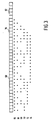
- Figure 3 shows a particular coding scheme to be used in the invention.
- a single bit error correcting, double bit error detecting [30,24,4] Hamming bit code is used as an error protective code.
- block 60 contains the 24 user bits.
- Block 76 contains 6 redundant bits. Of these, 5 bits suffice to attain-single-bit error correction.
- the sixth bit raises that level to simultaneous single-bit error correction and double bit error protection, corresponding to distance 4. In fact, distance 4 also allows triple bit error detection.
- Lines 64-74 show the formation of the six parity bits as follows. As indicated by the dots on line 64, the sixth parity bit is generated by even parity on all bits.
- the fifth parity bit is generated by even parity on all odd numbered bits, and so on for the further parity bits.
- the code as shown up to now is known in the art.
- the rank thereof is stored in the five remaining bits in part 62.
- the rank may be coded from 00001 to 11110 (HEX 1E).
- the absence of error may be represented by a dummy identifier (00000). If two errors are found, the rank of the first one is indicated by the discrepancy identifier. If three or more errors are found, an URD code 11111 (IF) is stored, signalling UnReliable Data.
- the standard decoding is undertaken for this particular code. If the decoding is successful, the reconstructed data is available to a user. If the amount of errors is too high, the outcome will generally be an incorrectibility signalization. In rather improbable situations, the errors will map the erroneous data word on another code word or rather on a data word that is correctable another to code word.
- the discrepancy identifier is inspected, to find an error that had been detected originally upon first write.
- the following codes may be found therein:
- case 1 The result of case 1 is that the stored data was already beyond correction, and an unreliability signal is sent to a user.
- case 2 the original error is directly pointed at; after inversion thereof, the decoding will present correct data.
- case 3 the decoding also after access of the discrepancy identifier will signal correctly the presence of exactly two incorrectible bit errors.
- Case 4 gives the same result as case 2: one error is inverted through the discrepancy identifier. Thereafter, the second error becomes correctable.
- Cases 5 and 6 are beyond correction, but also here, after inversion of the bit error identified by the discrepancy identifier, the presence of exactly two bit errors is correctly signalled. In all cases, an optimistic view is held.
- the later errors may or may not lead to a corrected word; correction or even detection are not guaranteed.
- the later errors are supposed to occur in the encoded data.
- the discrepancy identifier may comprise the extra error. In general, this will lead to pointing at an erroneous discrepancy position. The result of the decoding will then be dependent on the existence of an earlier error in the encoded data. If none, full correction is attained. If one, two errors are detected. The other possibilities will be clear now.
- the coding scheme used is particularly advantageous through the properties of the distance 4 code.
- the error protectivity is relatively high.
- the decoding is extremely simple because the discrepancy identifier may control the correcting of one error simply through inverting.
- a conventional [35,24,5] code may also correct two errors, but necessitates a decoder of much greater complexity.
- the only advantage of the latter code is that the two errors may occur at any instant in time .
- the two-error correctability requires that one error occurs at first write.
- this is no disadvantage, because in the environment of a matrix memory, in particular an EEPROM or the like, a great fraction of the errors will occur at the write operation.
- the present invention in case at least one error occurs at the original write phase, guarantees three error detection (including one original write error).
- tail point to an error position found during read-back, and add a parity bit over the tail to get odd parity. If at later read-out the tail has odd weight, the original error protection code is used without heeding the tail. If the tail has even weight however, the bit to which it is pointing, is inverted, and the original error protecting code is used on the information so modified.
- a Reed-Solomon code may be used. For example, with a user word of 24 bytes, adding four bytes would provide double byte error correctability. If now, upon reading directly after encoding, the storage is found to have one or more erroneous bytes, the rank numbers of the first two thereof are stored as discrepancy identifier. This allows the decoder later on to directly go to a two-erasure, one error strategy. Usually it is preferable to store the rank number of each erroneous byte also in the form of a byte, in case the hardware used is byte-oriented. However, this is not a prequisite.
- the erasure is generally treated by a standard correcting procedure, because the one-bit inversion technique is not possible here.
- the erasure may be brought about by an arbitrary bit error pattern in the erroneous byte or bytes.
- the procedure considered for Reed-Solomon codes can be used advantageously for an arbitrary code distance. Also here, the decoding is much easier than would be the case when the discrepancy identifier were replaced by extra distance producing symbols of the Reed-Solomon code.
Landscapes
- Engineering & Computer Science (AREA)
- Theoretical Computer Science (AREA)
- Quality & Reliability (AREA)
- Physics & Mathematics (AREA)
- General Engineering & Computer Science (AREA)
- General Physics & Mathematics (AREA)
- Multimedia (AREA)
- Signal Processing (AREA)
- Techniques For Improving Reliability Of Storages (AREA)
- Detection And Correction Of Errors (AREA)
- Error Detection And Correction (AREA)
Abstract
Description
- encoding the data by an error protecting code to encoded data
- storing the encoded data in a medium as stored data
- reading the stored data from the medium and comparing with the encoded data.
- upon detecting a particular discrepancy between stored data and encoded data generating a discrepancy identifier
- storing the discrepancy identifier in association with the stored data as stored identifier, thereby raising error protection offered by said error protecting code.
- an error protecting encoder for encoding the data to encoded data
- memory medium means for storing said encoded data
- memory access means for writing said encoded data in the memory as stored data and for reading said stored data from the medium
- comparing means connected to said access means for comparing said encoded data with said stored data,
Claims (14)
- A method for error-protective encoding of data, said method comprising the steps of:characterized byencoding the data by an error protecting code to encoded datastoring said encoded data in a medium as stored datareading said stored data from the medium and comparing with said encoded data,upon detecting a particular discrepancy between said stored data and said encoded data generating a discrepancy identifierstoring said discrepancy identifier in association with said stored data as stored identifier, thereby raising error protection offered by said error protecting code.
- A method as claimed in Claim 1, wherein upon absent detecting of a discrepancy, a dummy identifier is stored.
- A method as claimed in Claims 1 or 2, wherein said discrepancy as identified by the discrepancy identifier is within the error correcting capability of the error protecting code.
- A method as claimed in Claims 1, 2 or 3, wherein said error protecting code is a block code.
- A method as claimed in any of Claims 1 to 4, wherein said error protecting code is a bit error correcting code, and said discrepancy identifier is a bit error identifier.
- A method as claimed in any of Claims 1 to 5, wherein said error correcting code is a Hamming code or a Reed Solomon code.
- A method as claimed in Claim 6, wherein said medium is matrix-organized.
- A device for error-protective encoding of data, said device comprising:characterized by secondary encoding means fed by the comparing means for under control of detection of a particular discrepancy between said stored data and said encoded data generating a discrepancy identifier for presentation to said memory access means, for storing said discrepancy identifier with said stored data as stored identifier as additional error protection for said stored data.an error protecting encoder for encoding the data to encoded datamemory medium means for storing said encoded datamemory access means for writing said encoded data in the memory as stored data and for reading said stored data from the mediumcomparing means connected to said access means for comparing said encoded data with said stored data,
- A device as claimed in Claim 8, wherein said medium is matrix-organized.
- A method for decoding data that has been encoded according to a method as claimed in any of Claims 1 to 7, said method comprising the steps of reading and decoding said encoded data, and upon so attaining correctly decoded data forwarding said decoded data to a user, and furthermore, accessing a discrepancy identifier stored in association with the encoded data, under control of said discrepancy identifier amending said encoded data to correctible data, and decoding the correctible data to correctly decoded data for forwarding to a user.
- A method as claimed in Claim 10, combined with detecting an UnReliable Data value in said discrepancy identifier and thereupon signalling an unreliability signal to a user.
- A device for decoding data that has been encoded according to a method as claimed in any of Claims 1 to 7, said device comprising medium access means for reading and decoding said encoded data, detection means fed by said access means for detecting correctly decoded data for forwarding said decoded data to a user, furthermore detection/amending means for accessing a discrepancy identifier stored in association with the encoded data, and under control of said discrepancy identifier amending said encoded data to correctible data, and said decoding being fed by said further detection/amending means for decoding the correctible data to correctly decoded data for forwarding to a user.
- A device as claimed in Claim 12, wherein said detection means have an UnReliable Data output for under control of an UnReliable Data value in said discrepancy identifier signalling an unreliability signal to a user.
- A storage medium for storing data generated by a method as claimed in any of Claims 1 to 7, and for interfacing to a device as claimed in Claims 12 or 13, said storage medium having a plurality of uniform-sized storage locations each accommodating storage of an encoded data unit and an associated discrepancy identifier, and said storage medium allowing location-wise access thereto.
Priority Applications (1)
| Application Number | Priority Date | Filing Date | Title |
|---|---|---|---|
| EP96935199A EP0803094B1 (en) | 1995-11-10 | 1996-10-30 | Method and device for error protection of programmable memories |
Applications Claiming Priority (4)
| Application Number | Priority Date | Filing Date | Title |
|---|---|---|---|
| EP95203072 | 1995-11-10 | ||
| EP95203072 | 1995-11-10 | ||
| EP96935199A EP0803094B1 (en) | 1995-11-10 | 1996-10-30 | Method and device for error protection of programmable memories |
| PCT/IB1996/001164 WO1997017655A1 (en) | 1995-11-10 | 1996-10-30 | Method and device for error protection of programmable memories |
Publications (2)
| Publication Number | Publication Date |
|---|---|
| EP0803094A1 EP0803094A1 (en) | 1997-10-29 |
| EP0803094B1 true EP0803094B1 (en) | 2002-02-20 |
Family
ID=8220823
Family Applications (1)
| Application Number | Title | Priority Date | Filing Date |
|---|---|---|---|
| EP96935199A Expired - Lifetime EP0803094B1 (en) | 1995-11-10 | 1996-10-30 | Method and device for error protection of programmable memories |
Country Status (6)
| Country | Link |
|---|---|
| US (1) | US5896397A (en) |
| EP (1) | EP0803094B1 (en) |
| JP (1) | JPH10512697A (en) |
| KR (1) | KR100715878B1 (en) |
| DE (1) | DE69619359T2 (en) |
| WO (1) | WO1997017655A1 (en) |
Families Citing this family (4)
| Publication number | Priority date | Publication date | Assignee | Title |
|---|---|---|---|---|
| JP3094957B2 (en) * | 1997-06-30 | 2000-10-03 | 日本電気株式会社 | Radio base station reception data transmission system in uplink selection site diversity of mobile communication system |
| US7047481B2 (en) * | 2001-10-26 | 2006-05-16 | Koninklijke Philips Electronics N.V. | Decoding method and decoder for Reed Solomon code |
| US7220233B2 (en) * | 2003-04-08 | 2007-05-22 | Flowcardia, Inc. | Ultrasound catheter devices and methods |
| US9466301B2 (en) * | 2012-11-07 | 2016-10-11 | Kenneth John Lannes | System and method for linear frequency translation, frequency compression and user selectable response time |
Family Cites Families (9)
| Publication number | Priority date | Publication date | Assignee | Title |
|---|---|---|---|---|
| NL7804673A (en) * | 1978-05-02 | 1979-11-06 | Philips Nv | SYSTEM FOR TRANSFERRING BINARY INFORMATION ON SOME CHANNELS |
| JPS58105500A (en) * | 1981-11-23 | 1983-06-23 | スペリ・コ−ポレ−シヨン | Memory drive circuit failure detection system and method |
| NL8105799A (en) * | 1981-12-23 | 1983-07-18 | Philips Nv | SYSTEM FOR THE TRANSFER OF A TELEVISION IMAGE INFORMATION BY AN ERROR-PROTECTIVE CODE, IMAGER WITH DEVICE FOR GENERATING SUCH A PROTECTIVE CODE, AND THE DISPLAYING COVERING THE COATING OF THE COURTICTION IN THE COURSE OF THE COURTICLE. |
| DE3319710A1 (en) * | 1983-05-31 | 1984-12-06 | Siemens AG, 1000 Berlin und 8000 München | MEMORY CONTROL ARRANGEMENT, ESPECIALLY FOR AN ERROR-TOLERANT TELEPHONE MEDIATION SYSTEM |
| NL8701996A (en) * | 1987-08-26 | 1989-03-16 | Philips Nv | SEMICONDUCTOR MEMORIES INCLUDED WITH AN INCLUDED ERROR CORRECTION DEVICE, AND INTEGRATED CIRCUIT PROVIDED WITH SUCH A SEMICONDUCTOR MEMORY. |
| ATE132986T1 (en) * | 1988-08-02 | 1996-01-15 | Siemens Ag | METHOD FOR ERROR PROTECTION IN STORAGE SYSTEMS OF DATA PROCESSING SYSTEMS, IN PARTICULAR TELEPHONE SWITCHING SYSTEMS |
| ES2103719T3 (en) * | 1990-01-18 | 1997-10-01 | Philips Electronics Nv | REVERSIBLE DIGITAL DATA STORAGE DEVICE ON A MULTI-TRACK MEDIA, DECODING DEVICE FOR INFORMATION REPRODUCTION TO BE USED WITH SUCH MEDIA, AND STORAGE SUPPORT FOR USE WITH SUCH STORAGE DEVICE |
| NL9100218A (en) * | 1991-02-07 | 1992-09-01 | Philips Nv | ENCODE / DECODE SWITCH AND DIGITAL VIDEO SYSTEM FITTED WITH THE SWITCH. |
| EP0603932B1 (en) * | 1992-12-14 | 1998-04-08 | Koninklijke Philips Electronics N.V. | Method and apparatus for implementing a quasi-product code with different degrees of protection against errors |
-
1996
- 1996-10-30 EP EP96935199A patent/EP0803094B1/en not_active Expired - Lifetime
- 1996-10-30 KR KR1019970704818A patent/KR100715878B1/en not_active Expired - Fee Related
- 1996-10-30 JP JP9518012A patent/JPH10512697A/en active Pending
- 1996-10-30 DE DE69619359T patent/DE69619359T2/en not_active Expired - Fee Related
- 1996-10-30 WO PCT/IB1996/001164 patent/WO1997017655A1/en not_active Ceased
- 1996-11-12 US US08/744,165 patent/US5896397A/en not_active Expired - Fee Related
Also Published As
| Publication number | Publication date |
|---|---|
| US5896397A (en) | 1999-04-20 |
| KR100715878B1 (en) | 2007-12-07 |
| JPH10512697A (en) | 1998-12-02 |
| KR19980701428A (en) | 1998-05-15 |
| DE69619359D1 (en) | 2002-03-28 |
| WO1997017655A1 (en) | 1997-05-15 |
| DE69619359T2 (en) | 2002-10-24 |
| EP0803094A1 (en) | 1997-10-29 |
Similar Documents
| Publication | Publication Date | Title |
|---|---|---|
| US5757824A (en) | Code error correction apparatus | |
| US5182752A (en) | Method and apparatus for transferring data between a data bus and a data storage device | |
| CA1275739C (en) | Error correction method | |
| KR960003094B1 (en) | Error correction code generator | |
| US6018817A (en) | Error correcting code retrofit method and apparatus for multiple memory configurations | |
| EP0332662B1 (en) | Byte write error code method and apparatus | |
| US6012839A (en) | Method and apparatus to protect data within a disk drive buffer | |
| US6367047B1 (en) | Multi-level error detection and correction technique for data storage recording device | |
| EP1500200B1 (en) | Method and apparatus for embedding an additional layer of error correction into an error correcting code | |
| US20070283214A1 (en) | Corruption-resistant data porting with multiple error correction schemes | |
| US7168026B2 (en) | Method and apparatus for preservation of failure state in a read destructive memory | |
| US20200007168A1 (en) | Data storage system and associated data storing method for reducing data error rate | |
| EP0803094B1 (en) | Method and device for error protection of programmable memories | |
| CN115729746A (en) | A method for protecting stored data based on CRC and ECC | |
| US7073024B1 (en) | Data protection method wherein data protection code is stored together with parity | |
| EP0850473A1 (en) | A method and apparatus for trackwise burst error correction in a multitrack storage format | |
| US6615384B1 (en) | Encoding/decoding method and apparatus and disk storage device | |
| JP2005011386A (en) | Error correction apparatus | |
| JPS567299A (en) | Error correcting circuit | |
| US11775387B2 (en) | Cyclic redundancy check (CRC) retry for memory systems in compute express link (CXL) devices | |
| TWI708256B (en) | Memory apparatus, memory controller and data accessing method thereof | |
| KR20000020028A (en) | Method for encoding/decoding flash memory | |
| CN120994121A (en) | A data integrity verification method, apparatus, and electronic device | |
| TW591670B (en) | Memory device | |
| JPS62254540A (en) | Error correction device |
Legal Events
| Date | Code | Title | Description |
|---|---|---|---|
| PUAI | Public reference made under article 153(3) epc to a published international application that has entered the european phase |
Free format text: ORIGINAL CODE: 0009012 |
|
| AK | Designated contracting states |
Kind code of ref document: A1 Designated state(s): DE FR GB |
|
| 17P | Request for examination filed |
Effective date: 19971117 |
|
| GRAG | Despatch of communication of intention to grant |
Free format text: ORIGINAL CODE: EPIDOS AGRA |
|
| 17Q | First examination report despatched |
Effective date: 20010423 |
|
| GRAG | Despatch of communication of intention to grant |
Free format text: ORIGINAL CODE: EPIDOS AGRA |
|
| GRAH | Despatch of communication of intention to grant a patent |
Free format text: ORIGINAL CODE: EPIDOS IGRA |
|
| GRAH | Despatch of communication of intention to grant a patent |
Free format text: ORIGINAL CODE: EPIDOS IGRA |
|
| REG | Reference to a national code |
Ref country code: GB Ref legal event code: IF02 |
|
| GRAA | (expected) grant |
Free format text: ORIGINAL CODE: 0009210 |
|
| AK | Designated contracting states |
Kind code of ref document: B1 Designated state(s): DE FR GB |
|
| REF | Corresponds to: |
Ref document number: 69619359 Country of ref document: DE Date of ref document: 20020328 |
|
| ET | Fr: translation filed | ||
| PLBE | No opposition filed within time limit |
Free format text: ORIGINAL CODE: 0009261 |
|
| STAA | Information on the status of an ep patent application or granted ep patent |
Free format text: STATUS: NO OPPOSITION FILED WITHIN TIME LIMIT |
|
| 26N | No opposition filed |
Effective date: 20021121 |
|
| PGFP | Annual fee paid to national office [announced via postgrant information from national office to epo] |
Ref country code: FR Payment date: 20061025 Year of fee payment: 11 |
|
| PGFP | Annual fee paid to national office [announced via postgrant information from national office to epo] |
Ref country code: GB Payment date: 20061030 Year of fee payment: 11 |
|
| PGFP | Annual fee paid to national office [announced via postgrant information from national office to epo] |
Ref country code: DE Payment date: 20061227 Year of fee payment: 11 |
|
| GBPC | Gb: european patent ceased through non-payment of renewal fee |
Effective date: 20071030 |
|
| PG25 | Lapsed in a contracting state [announced via postgrant information from national office to epo] |
Ref country code: DE Free format text: LAPSE BECAUSE OF NON-PAYMENT OF DUE FEES Effective date: 20080501 |
|
| REG | Reference to a national code |
Ref country code: FR Ref legal event code: ST Effective date: 20080630 |
|
| PG25 | Lapsed in a contracting state [announced via postgrant information from national office to epo] |
Ref country code: GB Free format text: LAPSE BECAUSE OF NON-PAYMENT OF DUE FEES Effective date: 20071030 |
|
| PG25 | Lapsed in a contracting state [announced via postgrant information from national office to epo] |
Ref country code: FR Free format text: LAPSE BECAUSE OF NON-PAYMENT OF DUE FEES Effective date: 20071031 |