EP0803027B1 - Fuel injection device for an internal combustion engine - Google Patents
Fuel injection device for an internal combustion engine Download PDFInfo
- Publication number
- EP0803027B1 EP0803027B1 EP96931751A EP96931751A EP0803027B1 EP 0803027 B1 EP0803027 B1 EP 0803027B1 EP 96931751 A EP96931751 A EP 96931751A EP 96931751 A EP96931751 A EP 96931751A EP 0803027 B1 EP0803027 B1 EP 0803027B1
- Authority
- EP
- European Patent Office
- Prior art keywords
- fuel
- heating element
- injection device
- valve
- fuel injection
- Prior art date
- Legal status (The legal status is an assumption and is not a legal conclusion. Google has not performed a legal analysis and makes no representation as to the accuracy of the status listed.)
- Expired - Lifetime
Links
- 239000000446 fuel Substances 0.000 title claims description 130
- 239000007924 injection Substances 0.000 title claims description 58
- 238000002347 injection Methods 0.000 title claims description 58
- 238000002485 combustion reaction Methods 0.000 title claims description 23
- 238000010438 heat treatment Methods 0.000 claims description 74
- 239000006200 vaporizer Substances 0.000 claims description 13
- 239000000463 material Substances 0.000 claims description 7
- 239000011148 porous material Substances 0.000 claims description 3
- 229910001111 Fine metal Inorganic materials 0.000 claims description 2
- 239000000919 ceramic Substances 0.000 claims description 2
- 210000002268 wool Anatomy 0.000 claims description 2
- 238000011144 upstream manufacturing Methods 0.000 claims 1
- 239000007921 spray Substances 0.000 description 17
- 239000007789 gas Substances 0.000 description 14
- 239000007788 liquid Substances 0.000 description 9
- 239000000203 mixture Substances 0.000 description 7
- 238000002360 preparation method Methods 0.000 description 5
- 238000001704 evaporation Methods 0.000 description 4
- 230000008020 evaporation Effects 0.000 description 4
- 239000012530 fluid Substances 0.000 description 4
- 238000007789 sealing Methods 0.000 description 4
- 238000000889 atomisation Methods 0.000 description 3
- 230000015572 biosynthetic process Effects 0.000 description 3
- 241000446313 Lamella Species 0.000 description 2
- 230000001771 impaired effect Effects 0.000 description 2
- 230000001133 acceleration Effects 0.000 description 1
- 230000006835 compression Effects 0.000 description 1
- 238000007906 compression Methods 0.000 description 1
- 238000010276 construction Methods 0.000 description 1
- 238000001816 cooling Methods 0.000 description 1
- 230000001419 dependent effect Effects 0.000 description 1
- 238000005485 electric heating Methods 0.000 description 1
- 239000003344 environmental pollutant Substances 0.000 description 1
- 238000009413 insulation Methods 0.000 description 1
- 238000004519 manufacturing process Methods 0.000 description 1
- 230000002093 peripheral effect Effects 0.000 description 1
- 231100000719 pollutant Toxicity 0.000 description 1
- 230000001105 regulatory effect Effects 0.000 description 1
- 230000002269 spontaneous effect Effects 0.000 description 1
- 239000012899 standard injection Substances 0.000 description 1
- 230000036962 time dependent Effects 0.000 description 1
Images

Classifications
-
- F—MECHANICAL ENGINEERING; LIGHTING; HEATING; WEAPONS; BLASTING
- F02—COMBUSTION ENGINES; HOT-GAS OR COMBUSTION-PRODUCT ENGINE PLANTS
- F02M—SUPPLYING COMBUSTION ENGINES IN GENERAL WITH COMBUSTIBLE MIXTURES OR CONSTITUENTS THEREOF
- F02M31/00—Apparatus for thermally treating combustion-air, fuel, or fuel-air mixture
- F02M31/02—Apparatus for thermally treating combustion-air, fuel, or fuel-air mixture for heating
- F02M31/12—Apparatus for thermally treating combustion-air, fuel, or fuel-air mixture for heating electrically
-
- F—MECHANICAL ENGINEERING; LIGHTING; HEATING; WEAPONS; BLASTING
- F02—COMBUSTION ENGINES; HOT-GAS OR COMBUSTION-PRODUCT ENGINE PLANTS
- F02M—SUPPLYING COMBUSTION ENGINES IN GENERAL WITH COMBUSTIBLE MIXTURES OR CONSTITUENTS THEREOF
- F02M53/00—Fuel-injection apparatus characterised by having heating, cooling or thermally-insulating means
- F02M53/04—Injectors with heating, cooling, or thermally-insulating means
- F02M53/06—Injectors with heating, cooling, or thermally-insulating means with fuel-heating means, e.g. for vaporising
-
- F—MECHANICAL ENGINEERING; LIGHTING; HEATING; WEAPONS; BLASTING
- F02—COMBUSTION ENGINES; HOT-GAS OR COMBUSTION-PRODUCT ENGINE PLANTS
- F02M—SUPPLYING COMBUSTION ENGINES IN GENERAL WITH COMBUSTIBLE MIXTURES OR CONSTITUENTS THEREOF
- F02M61/00—Fuel-injectors not provided for in groups F02M39/00 - F02M57/00 or F02M67/00
- F02M61/04—Fuel-injectors not provided for in groups F02M39/00 - F02M57/00 or F02M67/00 having valves, e.g. having a plurality of valves in series
- F02M61/08—Fuel-injectors not provided for in groups F02M39/00 - F02M57/00 or F02M67/00 having valves, e.g. having a plurality of valves in series the valves opening in direction of fuel flow
-
- F—MECHANICAL ENGINEERING; LIGHTING; HEATING; WEAPONS; BLASTING
- F02—COMBUSTION ENGINES; HOT-GAS OR COMBUSTION-PRODUCT ENGINE PLANTS
- F02M—SUPPLYING COMBUSTION ENGINES IN GENERAL WITH COMBUSTIBLE MIXTURES OR CONSTITUENTS THEREOF
- F02M69/00—Low-pressure fuel-injection apparatus ; Apparatus with both continuous and intermittent injection; Apparatus injecting different types of fuel
- F02M69/04—Injectors peculiar thereto
- F02M69/047—Injectors peculiar thereto injectors with air chambers, e.g. communicating with atmosphere for aerating the nozzles
-
- F—MECHANICAL ENGINEERING; LIGHTING; HEATING; WEAPONS; BLASTING
- F02—COMBUSTION ENGINES; HOT-GAS OR COMBUSTION-PRODUCT ENGINE PLANTS
- F02M—SUPPLYING COMBUSTION ENGINES IN GENERAL WITH COMBUSTIBLE MIXTURES OR CONSTITUENTS THEREOF
- F02M2200/00—Details of fuel-injection apparatus, not otherwise provided for
- F02M2200/24—Fuel-injection apparatus with sensors
-
- Y—GENERAL TAGGING OF NEW TECHNOLOGICAL DEVELOPMENTS; GENERAL TAGGING OF CROSS-SECTIONAL TECHNOLOGIES SPANNING OVER SEVERAL SECTIONS OF THE IPC; TECHNICAL SUBJECTS COVERED BY FORMER USPC CROSS-REFERENCE ART COLLECTIONS [XRACs] AND DIGESTS
- Y02—TECHNOLOGIES OR APPLICATIONS FOR MITIGATION OR ADAPTATION AGAINST CLIMATE CHANGE
- Y02T—CLIMATE CHANGE MITIGATION TECHNOLOGIES RELATED TO TRANSPORTATION
- Y02T10/00—Road transport of goods or passengers
- Y02T10/10—Internal combustion engine [ICE] based vehicles
- Y02T10/12—Improving ICE efficiencies
Definitions
- the invention relates to a fuel injection device for an internal combustion engine according to the preamble of the claim 1.
- a fuel evaporator has an evaporator chamber on, through an inlet port from an injector Fuel is injected.
- the evaporator chamber is an ordinary glow plug arranged in the heated Condition causes the fuel to evaporate.
- the Fuel vapor formed in the evaporator chamber can collectively with air flowing in through a corresponding air inlet the evaporator chamber flows through a small nozzle into the Inlet area of a downstream combustion chamber of an internal combustion engine flow out.
- the glow plug After a cold start after the warm-up phase the glow plug is switched off, the fuel is discharged through the evaporator chamber only due to the flowing through the evaporator chamber from the internal combustion engine sucked in air, whereby atomization through the small nozzle of the fuel should be reached.
- Such a heating element in the injection region of the injection valve not heated, so it represents a relatively large one Obstacle to the sprayed fuel jet and interferes with the fuel preparation for the mixture formation.
- Another known fuel injection device (DE 20 57 972 C3) comprises the individual combustion chambers of an internal combustion engine associated injectors, those of one Fuel metering device is supplied with fuel via pipelines becomes.
- the fuel supplied goes into a Valve chamber of the respective injection valve, the outlet side is closed by an outlet valve.
- the exhaust valve includes a valve body by a spring in its closed position is biased and that of the fuel pressure in the valve chamber is opened when that of this force exerted on the valve body is the closing force of the spring exceeds.
- Each injector has one inside Radiator with which the one in the injection valve Fuel can be heated so that it is even when the engine is cold evaporates when it flows out through the exhaust valve and expanded in the outlet area of the injection valve.
- the chamber-like in a housing structure Evaporator area connects to a receiving opening for the injector from which the at least partially then evaporated fuel largely perpendicular to Injection direction of the injector to the exhaust valve is promoted.
- the heating element protrudes into the chamber-like Evaporator area, around the in the evaporator area to heat injected fuel and at least partially evaporate. If the pressure of the im Evaporator area located fuel vapor one certain threshold value, this opens the evaporator area final exhaust valve, and the vaporized fuel is emitted directly towards a combustion chamber.
- DE 195 04 175.5 which i.a. as WHERE 96/24764, a device for Metering and atomization of fluid proposed.
- This Spray device has a base body, the one encloses inner chamber K, an inlet Z with a Backflow valve RV and a drain A with a spray valve AV are lockable.
- Heating element H arranged to evaporate the fluid is provided.
- the backflow valve RV provides one closable inlet of this device. That in the Chamber K arranged heating element H can also have several Individual heating elements EH.
- the heating elements H are always arranged in the middle part of the chamber K.
- the fuel injection device with the characteristic features of claim 1 has in contrast the advantage that the fuel vaporizer in all heating conditions, in heating mode for full or partial evaporation and in the unheated state, a very good fuel preparation guaranteed because the fuel is always with the preset pressure exits.
- the metering function of the standard injection valve by the Fuel vaporizer does not change as a constant Pressure difference between the fuel pressure in the injection valve and the pressure in the fuel evaporator through the opening pressure of the exhaust valve is ensured.
- the invention Fuel injector a first heating element, the the immediately downstream of the spray opening of the Injector is assigned to lying evaporator area, and a second one arranged directly on the outlet valve electric heating element independent of the at least one first heating element. It is advantageous that the outflowing, partly vaporous, partly liquid, hot Fuel from and the second heater heated outlet valve is additionally heated. The Evaporation of the fuel is carried out over the length of the Maintain exhaust valve effectively.
- Leave with the fuel injection device according to the invention therefore both pollutant emissions in particular during the cold start and during the warm-up phase as well Reduce fuel consumption because of a start and acceleration enrichment of the fuel-air mixture is eliminated.
- a gas duct comprising the fuel evaporator is provided, so you can even with the electric heater turned off Heating of the fuel during continuous operation of the Ensure the internal combustion engine if the gas duct has hot exhaust gases are supplied by the internal combustion engine. Will instead whose air is introduced into the gas channel, become liquid out of the exhaust valve fuel through the Airflow atomized very finely.
- NTC heating elements i.e. heating elements with positive temperature coefficients
- NTC heating elements i.e. heating elements with negative temperature coefficients
- the use of NTC heating elements is involved in terms of manufacturing costs and tolerances are advantageous and especially economical, if due to different fuel flow rates an external temperature control for the heating elements anyway is required.
- the invention Fuel injection device any common injection valve use with metering function.
- a fuel injection device for an internal combustion engine a fuel injector 10 on that in the usual way in its outlet side End face 11 has a spray opening 12, the a valve seat 14 cooperating with a valve needle 13 assigned.
- valve needle 13 one extending through the spray opening 12
- Spray pin 13 'on when the injector is open 10 to form a hosed fuel lamella so in the outlet opening 12 is arranged that in a spray area 15 hosed fuel fins essentially is cone-shaped.
- the formation of the fuel lamella or one shaped in any other desired manner or multi-part fuel jet can also on others Way to be achieved. So it is z. B. possible, a spray orifice plate to be provided with one or more spray holes or to design the outlet opening as an annular gap.
- a Fuel evaporator 16 placed tightly on a housing 17th with a sleeve-shaped mounting section 18.
- a on Inner circumference of the mounting section 18 formed ring web 19 engages in an end of the injection valve on the intake pipe side 10 provided annular groove 20 and thus holds the fuel evaporator 16 close to the injection valve 10.
- the attachment The fuel vaporizer 16 can also be used in other ways respectively.
- a tight press fit connection is also conceivable between fuel evaporator 16 and injection valve 10th
- the heating elements 23 are for power supply via a electrical line 25 which is electrically insulated but gas-tight is inserted into the housing 17, with a not shown Power source connected.
- the heating elements 23 consist Washers. But there are also other geometric configurations of the heating elements 23 conceivable.
- FIG. 2 shows, for example, two sleeve-shaped heating elements 23 ', which are arranged coaxially to one another and to the receiving sleeve 22 and are held by a common holding part 24.
- the holding part 24 is on the side facing away from the injection valve 10 Side of the heating elements 23 'provided and in not shown in such a way that it is the exit not hindered by fuel vapor from the evaporator area 21.
- the inner heating element 23 ' is expediently shown in Axial direction shorter than the outer.
- For electrical Connection is the heating elements 23 'via a branch line 26 connected to line 25.
- Fig. 3 shows a further embodiment of the heating elements 23, at of the heating elements 23 "concentric to each other and to the receiving sleeve 22 are arranged.
- the two heating elements 23 " are held on holding parts 24 at their axial ends.
- the evaporator area 21 is between the heating elements 23 " doing so with a porous material 27, e.g. B. with porous ceramics or fine metal wool, filled for heat transfer to further improve the fuel.
- the individual Heating elements 23, 23 'and 23 made of a PTC resistance material, So from a resistance material with a positive temperature coefficients exist. It is also possible, an NTC resistance material, i.e. a resistance material to be used with a negative temperature coefficient. In this case, external temperature control is required provided.
- a temperature control device not shown, the in a control unit for the Internal combustion engine can be integrated, the temperature the heating elements 23, 23 'and 23 "corresponding temperature signal fed. To form the temperature signal can either the temperature-dependent internal resistance of the heating elements 23, 23 'and 23 "are used, or there is an in the drawing, not shown temperature sensor on one of the heating elements 23, 23 'and 23 "arranged.
- heating elements 23, 23 'and 23 "from one NTC resistance material is particularly advantageous if if due to different fuel throughputs Temperature control for the heating elements 23, 23 'and 23 "anyway is required.
- the exhaust valve 30, which has an acicular valve body 31st with a closing head 32 on its remote from the injection valve 10 End and includes a valve seat 33 is in one Holding sleeve 34 arranged on the outside of a assembled state against the inside of the receiving sleeve 22
- Sealing ring 35 carries between a radially outwardly projecting Flange 36 of the holding sleeve 34 and also one outwardly projecting flange 37 one on the outside on the holding sleeve 34 arranged support sleeve 38 is inserted.
- the holding sleeve 34 On hers outlet-side end, the holding sleeve 34 has a radial inwardly extending retaining flange 34 'on which a Valve seat 33 supporting valve seat body 39 is attached.
- a closing spring 41 which is expedient is designed as a compression spring and between the valve seat body 39 and an end facing away from the closing head 32 of the valve body 31 arranged support plate 42 clamped is, towards the injection valve 10 in its closed position biased, in which the the outer region of the exhaust valve 30 associated closing head 32 abuts the valve seat 33.
- the valve closing force generated by the closing spring 41 becomes preset so that the exhaust valve 30 at an inner Pressure from 2000 hPa to 4000 hPa opens.
- the z. B. from a permanent magnet is provided.
- the outlet valve 30 is another, sleeve-shaped heating element 43 assigned, which is attached to the valve seat body 39 and the valve body 31 and the closing spring 41 surrounds.
- the heating element 43 is on the one hand with the electrical Line 25 and on the other hand with an outer peripheral portion connected to the holding sleeve 34.
- Casing 17 comprising casing sleeve 50 is provided, which with the housing 17 together an annular cylindrical gas channel 51 forms the air on the inlet side or preferably from the internal combustion engine recirculated exhaust gas via a connection piece 52 can be fed.
- the jacket sleeve 50 flange-like bent inwards and lies with the bent Section 53 close to the housing 17.
- the housing 17 has at its end facing away from the injection valve 10 in Fuel injection direction seen behind the investment area of the sealing ring 35 has a plurality of outlet openings 54, arranged circumferentially at equal intervals, for example are.
- To guide 34 extends that facing away from the injector 10 End of the housing 17 or the receiving sleeve 22 to front end of the holding sleeve 34 for the outlet valve 30 and thus forms together with the holding sleeve 34 surrounding it exit cylinder 55 in the form of a ring cylinder for the air or exhaust flow front section the receiving sleeve 22, which surrounds the outlet channel 55 on the outside, can be slightly tapered inwards.
- the gas channel 51 comprising the fuel evaporator 16 is designed together with the outlet openings 54 so that air supplied or exhaust gas recirculated from the internal combustion engine at high speed from between the holding sleeve 34 and receiving sleeve 22 formed, annular-gap-shaped gas outlet opening 56 exits.
- Suction pipe 60 is a radially U-shaped in cross section externally open retaining ring 61 is provided on the casing sleeve 50, in which a sealing ring 62 is inserted, which in the installed state on an inner wall 63 of a corresponding opening 64 fits tightly in the intake manifold 60.
- the retaining ring 61 is used together with the sealing ring 62 as thermal insulation between the Fuel evaporator 16 and the intake manifold 60 of the internal combustion engine. If the sleeve 50 to form the fuel evaporator 16 comprehensive gas channel 51 is not provided is the retaining ring 61 directly on the housing 17th placed.
- Heating element 43 electrically heated. From the fuel meter Injection valve 10 in the spray area 15 in the fuel evaporator 16 injected fuel gets in from there the evaporator area 21, whereby it is applied to the heating elements 23, 23 ', 23 ", the holding parts 24 and in the embodiment according to FIG. 3 also on the porous material 27 in the evaporator region 21 strikes, is heated and at least partially evaporated. Depending on the shape of the sprayed fuel jet can also some of the liquid fuel on the inner surface the receiving sleeve 22 hit. There he will when the receiving sleeve 22 is sufficiently heated, also evaporated.
- the evaporation of fuel increases the pressure inside of the evaporator 16 to the preset opening pressure is reached, the outlet valve 30 opens and Fuel flows out.
- the outflowing, partly vaporous, partly liquid, hot fuel is from the heating element 43 and the exhaust valve 30 heated therefrom additionally heated.
- the heating elements are to provide a fuel / air mixture 23, 23 'and 23 "are designed accordingly and / or by the temperature control device controlled accordingly.
- a major advantage of the fuel evaporator according to the invention 16 is that the injection of liquid Fuel and the discharge of the hot fuel-fuel vapor mixture without affecting fuel metering can overlap in time without the metering function of the injection valve 10 is impaired.
- the fuel evaporator 16 is thereby heated up, and there is fuel evaporation reach without additional electrical heating.
- the air can be introduced into the gas channel 51 Support fuel atomization.
Landscapes
- Engineering & Computer Science (AREA)
- Chemical & Material Sciences (AREA)
- Combustion & Propulsion (AREA)
- Mechanical Engineering (AREA)
- General Engineering & Computer Science (AREA)
- Fuel-Injection Apparatus (AREA)
Description
Die Erfindung betrifft eine Kraftstoffeinspritzvorrichtung für einen Verbrennungsmotor nach dem Oberbegriff des Anspruchs 1.The invention relates to a fuel injection device for an internal combustion engine according to the preamble of the claim 1.
Bei einer derartigen bekannten Kraftstoffeinspritzvorrichtung (GB 2 281 101 A) weist ein Kraftstoffverdampfer eine Verdampferkammer auf, in die durch eine Einlaßöffnung von einem Einspritzventil Kraftstoff eingespritzt wird. In der Verdampferkammer ist eine gewöhnliche Glühkerze angeordnet, die im beheizten Zustand eine Verdampfung des Kraftstoffs bewirkt. Der in der Verdampferkammer gebildete Kraftstoffdampf kann zusammen mit Luft, die durch einen entsprechenden Lufteinlaß in die Verdampferkammer einströmt, durch eine kleine Düse in den Einlaßbereich einer nachgeordneten Brennkammer eines Verbrennungsmotors ausströmen.In such a known fuel injection device (GB 2 281 101 A), a fuel evaporator has an evaporator chamber on, through an inlet port from an injector Fuel is injected. In the evaporator chamber is an ordinary glow plug arranged in the heated Condition causes the fuel to evaporate. The Fuel vapor formed in the evaporator chamber can collectively with air flowing in through a corresponding air inlet the evaporator chamber flows through a small nozzle into the Inlet area of a downstream combustion chamber of an internal combustion engine flow out.
Wird nach einem Kaltstart nach Beendigung der Warmlaufphase die Glühkerze abgeschaltet, so erfolgt der Kraftstoffaustrag durch die Verdampferkammer hindurch nur noch aufgrund der durch die Verdampferkammer strömenden, vom Verbrennungsmotor angesaugten Luft, wobei durch die kleine Düse eine Zerstäubung des Kraftstoffs erreicht werden soll.After a cold start after the warm-up phase the glow plug is switched off, the fuel is discharged through the evaporator chamber only due to the flowing through the evaporator chamber from the internal combustion engine sucked in air, whereby atomization through the small nozzle of the fuel should be reached.
Bei einer anderen bekannten Kraftstoffeinspritzvorrichtung (DE 28 43 534 A1) ist saugrohrseitig vor der Abspritzöffnung im Kraftstoffaustrittsbereich eines Einspritzventils ein Heizelement mit Verdampferflächen angeordnet, auf die zu verdampfender Kraftstoff aufgespritzt wird. Ein vom Heizelement festgelegter Verdampferbereich ist dabei auslaßseitig offen. Bei dieser bekannten Kraftstoffeinspritzvorrichtung kann zur Verbesserung der Wärmeübertragung auf den Kraftstoff auch ein Heizelement mit einer Honigwabenstruktur vorgesehen sein, das auslaßseitig ebenfalls offen ist.In another known fuel injection device (DE 28 43 534 A1) is on the intake manifold side in front of the spray opening in the fuel outlet area of an injection valve Heating element arranged with evaporator surfaces on which to be evaporated Fuel is sprayed on. One from the heating element The specified evaporator area is open on the outlet side. In this known fuel injection device can Improve heat transfer to the fuel too Heating element with a honeycomb structure may be provided is also open on the outlet side.
Wird ein derartiges Heizelement im Abspritzbereich des Einspritzventils nicht beheizt, so stellt es ein relativ großes Hindernis für den abgespritzten Kraftstoffstrahl dar und stört die Kraftstoffaufbereitung für die Gemischbildung.Such a heating element in the injection region of the injection valve not heated, so it represents a relatively large one Obstacle to the sprayed fuel jet and interferes with the fuel preparation for the mixture formation.
Bei üblichen Kraftstoffverdampfern, die im Abspritzbereich eines Einspritzventils angeordnet sind, treten daher Probleme bei der Gemischaufbereitung, also bei der Aufbereitung des Kraftstoffs für die Bildung des Kraftstoffluftgemischs auf, wenn der Kraftstoffverdampfer während des Dauerbetriebs des Verbrennungsmotors elektrisch nicht beheizt wird, da der Kraftstoffverdampfer den vom Einspritzventil erzeugten Kraftstoffstrahl beeinträchtigt und damit den Kraftstoffaustrag stört.With conventional fuel vaporizers in the spray area of an injection valve, problems therefore arise in the mixture preparation, i.e. in the preparation of the Fuel for the formation of the fuel-air mixture, if the fuel vaporizer is in continuous operation of the Internal combustion engine is not heated electrically because of Fuel evaporator the fuel jet generated by the injector impaired and thus the fuel discharge disturbs.
Eine weitere bekannte Kraftstoffeinspritzvorrichtung (DE 20
57 972 C3) umfaßt den einzelnen Brennkammern eines Verbrennungsmotors
zugeordnete Einspritzventile, denen von einer
Kraftstoffzumeßeinrichtung über Rohrleitungen Kraftstoff zugeführt
wird. Der zugeführte Kraftstoff gelangt dabei in eine
Ventilkammer des jeweiligen Einspritzventils, die auslaßseitig
von einem Auslaßventil abgeschlossen wird. Das Auslaßventil
umfaßt dabei einen Ventilkörper, der von einer Feder in
seine Schließstellung vorgespannt ist und der vom Kraftstoffdruck
in der Ventilkammer geöffnet wird, wenn die von diesem
auf den Ventilkörper ausgeübte Kraft die Schließkraft der Feder
übersteigt.Another known fuel injection device (
Jedes Einspritzventil weist dabei in seinem Innern einen Heizkörper auf, mit dem der im Einspritzventil befindliche Kraftstoff so erwärmt werden kann, daß er auch bei kaltem Motor verdampft, wenn er durch das Auslaßventil ausströmt und im Austrittsbereich des Einspritzventils expandiert.Each injector has one inside Radiator with which the one in the injection valve Fuel can be heated so that it is even when the engine is cold evaporates when it flows out through the exhaust valve and expanded in the outlet area of the injection valve.
Aus der US 4,137,872 ist eine Kraftstoffeinspritzvorrichtung für einen Verbrennungsmotor bekannt, die mit einem zumessenden Einspritzventil und mit einem saugrohrseitig vor einer Abspritzöffnung des Einspritzventils angeordneten Kraftstoffverdampfer, der einen Verdampferbereich mit einem zugeordneten elektrischen Heizelement aufweist, ausgestattet ist. Den Verdampferbereich schließt ein Auslassventil auslassseitig ab.From US 4,137,872 is a fuel injection device known for an internal combustion engine with a metering injection valve and with an intake manifold side an injection opening of the injector Fuel vaporizer that has an evaporator area with a has associated electrical heating element equipped is. An outlet valve closes the evaporator area exhaust side.
Der kammerartig in einer Gehäusestruktur ausgebildete Verdampferbereich schließt sich an eine Aufnahmeöffnung für das Einspritzventil an, aus dem der zumindest teilweise verdampfte Brennstoff dann weitgehend senkrecht zur Einspritzrichtung des Einspritzventils zum Auslassventil befördert wird. Das Heizelement ragt in den kammerartigen Verdampferbereich, um den in den Verdampferbereich eingespritzten Kraftstoff zu erhitzen und wenigstens teilweise zu verdampfen. Übersteigt der Druck des im Verdampferbereich befindlichen Kraftstoffdampfes einen bestimmten Schwellwert, so öffnet das den Verdampferbereich abschließende Auslassventil, und der verdampfte Kraftstoff wird unmittelbar in Richtung einer Brennkammer abgegeben.The chamber-like in a housing structure Evaporator area connects to a receiving opening for the injector from which the at least partially then evaporated fuel largely perpendicular to Injection direction of the injector to the exhaust valve is promoted. The heating element protrudes into the chamber-like Evaporator area, around the in the evaporator area to heat injected fuel and at least partially evaporate. If the pressure of the im Evaporator area located fuel vapor one certain threshold value, this opens the evaporator area final exhaust valve, and the vaporized fuel is emitted directly towards a combustion chamber.
Des weiteren wird in der DE 195 04 175.5, die u.a. als WO 96/24764 nachveröffentlicht ist, eine Vorrichtung zum Zumessen und Zerstäuben von Fluid vorgeschlagen. Diese Abspritzvorrichtung weist einen Grundkörper auf, der eine innere Kammer K umschließt, wobei ein Zulauf Z mit einem Rückstromventil RV und ein Ablauf A mit einem Abspritzventil AV verschließbar sind. In der inneren Kammer ist ein Heizelement H angeordnet, das zum Verdampfen des Fluids vorgesehen ist. Das Rückstromventil RV stellt dabei einen verschließbaren Zulauf dieser Vorrichtung dar. Das in der Kammer K angeordnete Heizelement H kann auch mit mehreren Einzelheizelementen EH ausgestattet sein. Die Heizelemente H sind dabei stets im mittleren Teil der Kammer K angeordnet. Aufgrund der räumlichen Anordnung und des strukturellen Aufbaus des Abspritzventils AV in der Vorrichtung ist eine unmittelbare Zuordnung eines Heizelements zum Abspritzventil AV nicht möglich, so daß über die Strömungslänge des Abspritzventils AV bis zum eigentlichen Abspritzpunkt ED wieder eine Abkühlung des Fluids bzw. des Fluiddampfes erfolgt.Furthermore, DE 195 04 175.5, which i.a. as WHERE 96/24764, a device for Metering and atomization of fluid proposed. This Spray device has a base body, the one encloses inner chamber K, an inlet Z with a Backflow valve RV and a drain A with a spray valve AV are lockable. There is a in the inner chamber Heating element H arranged to evaporate the fluid is provided. The backflow valve RV provides one closable inlet of this device. That in the Chamber K arranged heating element H can also have several Individual heating elements EH. The heating elements H are always arranged in the middle part of the chamber K. Because of the spatial arrangement and the structural Construction of the spray valve AV in the device is one immediate assignment of a heating element to the spray valve AV not possible, so that over the flow length of the Spray valve AV up to the actual spray point ED cooling of the fluid or fluid vapor again he follows.
Die erfindungsgemäße Kraftstoffeinspritzvorrichtung mit den kennzeichnenden Merkmalen des Anspruches 1 hat demgegenüber den Vorteil, daß der Kraftstoffverdampfer in allen Heizzuständen, also bei einem Heizbetrieb für Voll- oder Teilverdampfung und im ungeheizten Zustand, eine sehr gute Kraftstoffaufbereitung gewährleistet, da der Kraftstoff stets mit dem voreingestellten Druck austritt. Dabei wird die Zumeßfunktion des standardmäßigen Einspritzventils durch den Kraftstoffverdampfer nicht verändert, da eine konstante Druckdifferenz zwischen dem Kraftstoffdruck im Einspritzventil und dem Druck im Kraftstoffverdampfer durch den Öffnungsdruck des Auslaßventils sichergestellt ist.The fuel injection device according to the invention with the characteristic features of claim 1 has in contrast the advantage that the fuel vaporizer in all heating conditions, in heating mode for full or partial evaporation and in the unheated state, a very good fuel preparation guaranteed because the fuel is always with the preset pressure exits. The metering function of the standard injection valve by the Fuel vaporizer does not change as a constant Pressure difference between the fuel pressure in the injection valve and the pressure in the fuel evaporator through the opening pressure of the exhaust valve is ensured.
In vorteilhafter Weise besitzt die erfindungsgemäße Kraftstoffeinspritzvorrichtung ein erstes Heizelement, das dem unmittelbar stromabwärts der Abspritzöffnung des Einspritzventils liegenden Verdampferbereich zugeordnet ist, und ein zweites am Auslassventil unmittelbar angeordnetes elektrisches Heizelement unabhängig von dem wenigstens einen ersten Heizelement. Dabei ist es von Vorteil, daß der ausströmende, teils dampfförmige, teils flüssige, heiße Kraftstoff von dem zweiten Heizelement und dem davon aufgeheizten Auslassventil zusätzlich aufgeheizt wird. Die Verdampfung des Kraftstoffs wird über die Länge des Auslassventils effektiv aufrechterhalten.Advantageously, the invention Fuel injector a first heating element, the the immediately downstream of the spray opening of the Injector is assigned to lying evaporator area, and a second one arranged directly on the outlet valve electric heating element independent of the at least one first heating element. It is advantageous that the outflowing, partly vaporous, partly liquid, hot Fuel from and the second heater heated outlet valve is additionally heated. The Evaporation of the fuel is carried out over the length of the Maintain exhaust valve effectively.
Mit der erfindungsgemäßen Kraftstoffeinspritzvorrichtung lassen sich daher sowohl die Schadstoffemissionen insbesondere beim Kaltstart und während der Warmlaufphase als auch der Kraftstoffverbrauch verringern, da eine Start- und Beschleunigungsanreicherung des Kraftstoffluftgemischs wegfällt.Leave with the fuel injection device according to the invention therefore both pollutant emissions in particular during the cold start and during the warm-up phase as well Reduce fuel consumption because of a start and acceleration enrichment of the fuel-air mixture is eliminated.
Da der gesamte Heizbereich im Kraftstoffverdampfer immer wieder mit flüssigem Kraftstoff gespült wird, lassen sich Ablagerungen sicher verhindern.Because the entire heating area in the fuel evaporator is always there deposits with liquid fuel prevent safely.
Die Gefahr einer Selbstentzündung des Kraftstoffs im Heizbereich des Kraftstoffverdampfers, also im Verdampferbereich, ist praktisch beseitigt, da dort nur Kraftstoff und/oder Kraftstoffdampf vorliegt.The risk of spontaneous combustion of the fuel in the heating area the fuel evaporator, i.e. in the evaporator area, is practically eliminated since there is only fuel and / or There is fuel vapor.
Durch die in den Unteransprüchen aufgeführten Maßnahmen sind vorteilhafte Ausgestaltungen und Verbesserungen der im Anspruch 1 angegebenen Kraftstoffeinspritzvorrichtung möglich.By the measures listed in the subclaims advantageous refinements and improvements in the claim 1 specified fuel injector possible.
Ist bei der erfindungsgemäßen Kraftstoffeinspritzvorrichtung ein den Kraftstoffverdampfer umfassender Gaskanal vorgesehen, so läßt sich auch bei abgeschalteter elektrischer Heizung eine Aufheizung des Kraftstoffs während des Dauerbetriebs des Verbrennungsmotors sicherstellen, wenn dem Gaskanal heiße Abgase vom Verbrennungsmotor zugeführt werden. Wird anstelle dessen Luft in den Gaskanal eingeleitet, so werden flüssig aus dem Auslaßventil austretende Kraftstoffanteile durch den Luftstrom sehr fein zerstäubt. Is in the fuel injection device according to the invention a gas duct comprising the fuel evaporator is provided, so you can even with the electric heater turned off Heating of the fuel during continuous operation of the Ensure the internal combustion engine if the gas duct has hot exhaust gases are supplied by the internal combustion engine. Will instead whose air is introduced into the gas channel, become liquid out of the exhaust valve fuel through the Airflow atomized very finely.
Neben der Verwendung von PTC-Heizelementen, also von Heizelementen mit positiven Temperaturkoeffizienten, können auch NTC-Heizelemente, also Heizelemente mit negativen Temperaturkoeffizienten, eingesetzt werden, die von einer externen Steuereinrichtung geregelt werden können. Die Verwendung von NTC-Heizelementen ist dabei hinsichtlich der Herstellungskosten und Toleranzen von Vorteil und insbesondere dann wirtschaftlich, wenn aufgrund verschiedener Kraftstoffdurchsätze eine externe Temperaturregelung für die Heizelemente ohnehin erforderlich ist.In addition to the use of PTC heating elements, i.e. heating elements with positive temperature coefficients, too NTC heating elements, i.e. heating elements with negative temperature coefficients, be used by an external Control device can be regulated. The use of NTC heating elements is involved in terms of manufacturing costs and tolerances are advantageous and especially economical, if due to different fuel flow rates an external temperature control for the heating elements anyway is required.
Da sich der Kraftstoffverdampfer ohne weiteres an beliebige Einspritzventile anpassen läßt, kann die erfindungsgemäße Kraftstoffeinspritzvorrichtung jedes gängige Einspritzventil mit Zumeßfunktion verwenden.Because the fuel vaporizer can be used by anyone Injector can be adjusted, the invention Fuel injection device any common injection valve use with metering function.
Ausführungsbeispiele der Erfindung sind in der Zeichnung vereinfacht dargestellt und in der nachfolgenden Beschreibung näher erläutert. Es zeigen:
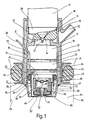
- Fig. 1
- einen schematischen Schnitt durch eine erfindungsgemäße Kraftstoffeinspritzvorrichtung,
- Fig. 2
- einen schematischen Schnitt durch einen Kraftstoffverdampfer einer erfindungsgemäßen Kraftstoffeinspritzvorrichtung mit einer anderen Ausführungsform der Heizelemente und
- Fig. 3
- einen schematischen Schnitt durch einen Kraftstoffverdampfer einer erfindungsgemäßen Kraftstoffeinspritzvorrichtung mit einer weiteren Ausführungsform der Heizelemente.
- Fig. 1
- 2 shows a schematic section through a fuel injection device according to the invention,
- Fig. 2
- a schematic section through a fuel evaporator of a fuel injection device according to the invention with another embodiment of the heating elements and
- Fig. 3
- a schematic section through a fuel evaporator of a fuel injection device according to the invention with a further embodiment of the heating elements.
In den verschiedenen Figuren der Zeichnung sind einander entsprechende Teile mit gleichen Bezugszeichen versehen.In the different figures of the drawing are corresponding to each other Provide parts with the same reference numerals.
Wie Fig. 1 zeigt, weist eine Kraftstoffeinspritzvorrichtung
für einen Verbrennungsmotor ein kraftstoffzumessendes Einspritzventil
10 auf, das in üblicher Weise in seiner auslaßseitigen
Stirnfläche 11 eine Abspritzöffnung 12 aufweist, der
ein mit einer Ventilnadel 13 zusammenwirkender Ventilsitz 14
zugeordnet ist.As shown in FIG. 1, a fuel injection device
for an internal combustion engine a
Im dargestellten Ausführungsbeispiel weist die Ventilnadel 13
einen sich durch die Abspritzöffnung 12 hindurch erstreckenden
Spritzzapfen 13' auf, der bei geöffnetem Einspritzventil
10 zur Formung einer abgespritzten Kraftstofflamelle so in
der Austrittsöffnung 12 angeordnet ist, daß die in einen Abspritzbereich
15 abgespritzte Kraftstofflamelle im wesentlichen
kegelmantelförmig ist. Die Ausbildung der Kraftstofflamelle
oder eines in anderer gewünschter Weise geformten, ein-
oder mehrteiligen Kraftstoffstrahls kann aber auch auf andere
Weise erreicht werden. So ist es z. B. möglich, eine Spritzlochscheibe
mit einem oder mehreren Spritzlöchern vorzusehen
oder die Austrittsöffnung als Ringspalt auszubilden.In the exemplary embodiment shown, the
Auf das saugrohrseitige Ende des Einspritzventils 10 ist ein
Kraftstoffverdampfer 16 dicht aufgesetzt, der ein Gehäuse 17
mit einem hülsenförmigen Montageabschnitt 18 umfaßt. Ein am
Innenumfang des Montageabschnitts 18 ausgebildeter Ringsteg
19 greift in eine am saugrohrseitigen Ende des Einspritzventils
10 vorgesehene Ringnut 20 ein und hält so den Kraftstoffverdampfer
16 dicht am Einspritzventil 10. Die Befestigung
des Kraftstoffverdampfers 16 kann auch in anderer Weise
erfolgen. Z. B. ist es auch möglich am Einspritzventil 10 einen
Ringsteg auszubilden, der dann von einem sich radial nach
innen erstreckenden Ringflansch umgriffen wird oder der in
eine geeignete, innen am Montageabschnitt 18 vorgesehene
Ringnut eingreift. Denkbar ist auch eine dichte Preßsitzverbindung
zwischen Kraftstoffverdampfer 16 und Einspritzventil
10.On the intake pipe end of the
An den Montageabschnitt 18 des Gehäuses 17 schließt sich eine
sich vom Einspritzventil 10 weg erstreckende, den freien Abspritzbereich
15 des Einspritzventils 10 und einen daran anschließenden
Verdampferbereich 21 umfangsmäßig umgebende Aufnahmehülse
22 an, in der zwei Heizelemente 23 in deren Axialrichtung
mit Abstand zueinander angeordnet und mittels metallischen
Halteteilen 24 mechanisch gehalten und elektrisch mit
Masse verbunden sind. Die Halteteile 24 sind dabei so ausgebildet,
daß sie die Wärmeübertragung von den Heizelemeten 23
auf den abgespritzten Kraftstoff unterstützen, das Einströmen
von Kraftstoff in den Verdampferbereich 21 jedoch nicht beeinträchtigen.One closes on the mounting
Die Heizelemente 23 sind dabei zur Stromversorgung über eine
elektrische Leitung 25, die elektrisch isoliert, aber gasdicht
in das Gehäuse 17 eingeführt ist, mit einer nicht dargestellten
Spannungsquelle verbunden.The
Wie in Fig. 1 dargestellt, bestehen die Heizelemente 23 aus
Ringscheiben. Es sind aber auch andere geometrische Ausgestaltungen
der Heizelemente 23 denkbar. As shown in Fig. 1, the
Fig. 2 zeigt beispielsweise zwei hülsenförmige Heizelemente
23', die koaxial zueinander und zu der Aufnahmehülse 22 angeordnet
und von einem gemeinsamen Halteteil 24 gehalten sind.
Das Halteteil 24 ist dabei auf der vom Einspritzventil 10 abgewandten
Seite der Heizelemente 23' vorgesehen und in nicht
näher dargestellter Weise so ausgebildet, daß es den Austritt
von Kraffstoffdampf aus dem Verdampferbereich 21 nicht behindert.
Zweckmäßigerweise ist das innere Heizelement 23' in
Axialrichtung kürzer ausgebildet als das äußere. Zum elektrischen
Anschluß sind die Heizelemente 23' über eine Zweigleitung
26 mit der Leitung 25 verbunden.2 shows, for example, two sleeve-shaped heating elements
23 ', which are arranged coaxially to one another and to the receiving
Fig. 3 zeigt eine weitere Ausbildung der Heizelemente 23, bei
der die Heizelemente 23" konzentrisch zueinander und zur Aufnahmehülse
22 angeordnet sind. Die beiden Heizelemete 23"
sind dabei an ihren axialen Enden an Halteteilen 24 gehalten.
Der Verdampferbereich 21 zwischen den Heizelementen 23" ist
dabei mit einem porösen Material 27, z. B. mit poröser Keramik
oder feiner Metallwolle, gefüllt, um die Wärmeübertragung
auf den Kraftstoff weiter zu verbessern.Fig. 3 shows a further embodiment of the
Unabhängig von ihrem geometrischen Aufbau können die einzelnen
Heizelemente 23, 23' und 23" aus einem PTC-Widerstandsmaterial,
also aus einem Widerstandsmaterial mit einem
positiven Temperaturkoeffizienten bestehen. Es ist aber auch
möglich, ein NTC-Widerstandsmaterial, also ein Widerstandsmaterial
mit negativem Temperaturkoeffizienten zu verwenden. In
diesem Fall ist es erforderlich, eine externe Temperaturregelung
vorzusehen. Hierfür wird einer nicht dargestellten Temperatursteuereinrichtung,
die in einem Steuergerät für den
Verbrennungsmotor integriert sein kann, ein der Temperatur
der Heizelemente 23, 23' und 23" entsprechendes Temperatursignal
zugeführt. Zur Bildung des Temperatursignals kann dabei
entweder der temperaturabhängige Innenwiderstand der Heizelemente
23, 23' und 23" verwendet werden, oder es wird ein in
der Zeichnung nicht dargestellter Temperaturfühler an einem
der Heizelemente 23, 23' und 23" angeordnet.Regardless of their geometric structure, the
Die Verwendung von Heizelementen 23, 23' und 23" aus einem
NTC-Widerstandsmaterial ist insbesondere dann von Vorteil,
wenn aufgrund unterschiedlicher Kraftstoffdurchsätze eine
Temperaturregelung für die Heizelemente 23, 23' und 23" ohnehin
erforderlich ist.The use of
In Ausströmrichtung des erzeugten Kraftstoffdampfes ist hinter
dem Verdampferbereich 21, also auf der vom Einspritzventil
10 abgewandten Seite der Heizelemente 23, 23' und 23" ein
vorzugsweise druckgeregeltes Auslaßventil 30 angeordnet, daß
den Verdampferbereich 21 auslaßseitig abschließt.In the outflow direction of the fuel vapor generated is behind
the
Das Auslaßventil 30, das einen nadelförmigen Ventilkörper 31
mit einem Schließkopf 32 an seinem vom Einspritzventil 10 abgewandten
Ende und einen Ventilsitz 33 umfaßt, ist in einer
Haltehülse 34 angeordnet, die auf ihrer Außenseite einen im
montierten Zustand innen an der Aufnahmehülse 22 anliegenden
Dichtring 35 trägt, der zwischen einem radial nach außen vorstehenden
Flansch 36 der Haltehülse 34 und einem ebenfalls
nach außen vorstehenden Flansch 37 einer außen auf der Haltehülse
34 angeordneten Stützhülse 38 eingesetzt ist. An ihrem
auslaßseitigen Ende weist die Haltehülse 34 einen sich radial
nach innen erstreckenden Halteflansch 34' auf, an dem ein den
Ventilsitz 33 tragender Ventilsitzkörper 39 befestigt ist.The
Der sich durch eine vom Ventilsitz 33 umgebene Durchgangsöffnung
40 im Ventilsitzkörper 39 hindurch erstreckende Ventilkörper
31 wird von einer Schließfeder 41, die zweckmäßigerweise
als Druckfeder ausgebildet ist und zwischen den Ventilsitzkörper
39 und eine am vom Schließkopf 32 abgewandten Ende
des Ventilkörpers 31 angeordnete Stützscheibe 42 eingespannt
ist, auf das Einspritzventil 10 hin in seine Schließstellung
vorgespannt, in welcher der dem Außenbereich des Auslaßventils
30 zugeordnete Schließkopf 32 am Ventilsitz 33 anliegt.The through a through opening surrounded by the
Die von der Schließfeder 41 erzeugte Ventilschließkraft wird
so voreingestellt, daß das Auslaßventil 30 bei einem inneren
Druck von 2000 hPa bis 4000 hPa öffnet.The valve closing force generated by the closing
Anstelle der mechanischen erzeugten Schließkraft könnte auch eine magnetische Schließkraft vorgesehen sein, die z. B. von einem Dauermagneten bereitgestellt wird.Instead of the mechanically generated closing force could also a magnetic closing force can be provided, the z. B. from a permanent magnet is provided.
Dem Auslaßventil 30 ist ein weiteres, hülsenförmiges Heizelement
43 zugeordnet, das auf dem Ventilsitzkörper 39 angebracht
ist und den Ventilkörper 31 sowie die Schließfeder 41
umgibt. Das Heizelement 43 ist einerseits mit der elektrischen
Leitung 25 und andererseits mit einem Außenumfangsabschnitt
mit der Haltehülse 34 verbunden.The
Wie in Fig. 1 weiter dargestellt ist, kann wahlweise eine das
Gehäuse 17 umfassende Mantelhülse 50 vorgesehen sein, die mit
dem Gehäuse 17 zusammen einen ringzylinderförmigen Gaskanal
51 bildet, dem einlaßseitig Luft oder vorzugsweise vom Verbrennungsmotor
rückgeführtes Abgas über einen Anschlußstutzen
52 zuführbar ist. Am auslaßseitigen Ende ist die Mantelhülse
50 flanschartig nach innen umgebogen und liegt mit dem umgebogenen
Abschnitt 53 dicht am Gehäuse 17 an. Das Gehäuse 17
weist an seinem vom Einspritzventil 10 abgewandten Ende in
Kraftstoffabspritzrichtung gesehen hinter dem Anlagebereich
des Dichtrings 35 eine Vielzahl von Auslaßöffnungen 54 auf,
die beispielsweise umfangsmäßig in gleichen Abständen angeordnet
sind.As further shown in Fig. 1, one can optionally
Casing 17 comprising
Um einen Luft- oder Abgasstrom außen entlang der Haltehülse
34 zu führen, erstreckt sich das vom Einspritzventil 10 abgewandte
Ende des Gehäuses 17 bzw. der Aufnahmehülse 22 bis zum
vorderen Ende der Haltehülse 34 für das Auslaßventil 30 und
bildet so zusammen mit der Haltehülse 34 einen diese umgebenden
ringzylinderartigen Austrittskanal 55. Der als Gasleitwand
für den Luft- oder Abgasstrom dienende vordere Abschnitt
der Aufnahmehülse 22, der den Austrittskanal 55 außen umgibt,
kann dabei leicht konisch nach innen zulaufend sein.To an air or exhaust gas flow outside along the holding sleeve
To guide 34 extends that facing away from the
Der den Kraftstoffverdampfer 16 umfassende Gaskanal 51 ist
dabei zusammen mit den Auslaßöffnungen 54 so ausgelegt, daß
zugeführte Luft oder vom Verbrennungsmotor rückgeführtes Abgas
mit hoher Geschwindigkeit aus einer zwischen Haltehülse
34 und Aufnahmehülse 22 gebildeten, ringspaltförmigen Gasausaustrittsöffnung
56 austritt.The
Zum Einbau der beschriebenen Kraftstoffeinspritzvorrichtung
in eine in Fig. 1 nur gestrichelt angedeutete Wand eines
Saugrohres 60 ist ein im Querschnitt U-förmiger, radial nach
außen offener Haltering 61 auf der Mantelhülse 50 vorgesehen,
in den ein Dichtring 62 eingelegt ist, der im eingebauten Zustand
an einer Innenwand 63 einer entsprechenden Öffnung 64
im Saugrohr 60 dicht anliegt. Der Haltering 61 dient dabei
zusammen mit dem Dichtring 62 als Wärmeisolation zwischen dem
Kraftstoffverdampfer 16 und dem Saugrohr 60 des Verbrennungsmotors.
Falls die Mantelhülse 50 zur Bildung des den Kraftstoffverdampfer
16 umfassenden Gaskanals 51 nicht vorgesehen
ist, wird der Haltering 61 unmittelbar auf das Gehäuse 17
aufgesetzt. To install the described fuel injection device
into a wall indicated only by dashed lines in FIG. 1
Beim Betrieb des Verbrennungsmotors werden nach dem Starten
während der Warmlaufphase die Heizelemente 23, 23' bzw. 23"
im Verdampferbereich sowie das dem Auslaßventil 30 zugeordnete
Heizelement 43 elektrisch geheizt. Vom kraftstoffzumessenden
Einspritzventil 10 in den Abspritzbereich 15 im Kraftstoffverdampfer
16 gespritzter Kraftstoff gelangt von dort in
den Verdampferbereich 21, wobei er auf die Heizelemente 23,
23', 23", die Halteteile 24 und bei der Ausführung nach Fig.
3 auch auf das poröse Material 27 im Verdampferbereich 21
auftrifft, aufgeheizt und zumindest teilweise verdampft wird.
Je nach der Form des abgespritzten Kraftstoffstrahls kann
auch ein Teil des flüssigen Kraftstoffs auf die Innenfläche
der Aufnahmehülse 22 auftreffen. Dort wird er, wenn die Aufnahmehülse
22 genügend aufgeheizt ist, ebenfalls verdampft.When operating the internal combustion engine, after starting
Durch die Kraftstoffverdampfung steigt der Druck im Inneren
des Kraftstoffverdampfers 16 an bis der voreingestellte Öffnungsdruck
erreicht ist, das Auslaßventil 30 öffnet und
Kraftstoff ausströmt. Der ausströmende, teils dampfförmige,
teils flüssige, heiße Kraftstoff wird von dem Heizelement 43
und dem davon aufgeheizten Auslaßventil 30 zusätzlich aufgeheizt.The evaporation of fuel increases the pressure inside
of the
Beim Ausströmen des unter definiertem Druck stehenden, heißen
Kraftstoff-Kraftstoffdampf-Gemischs in das Saugrohr 60 wird
durch die Expansion zusätzlich flüssiger Kraftstoff verdampft.
Um das Dampf-Flüssigkeits-Verhältnis des Kraftstoffs
im Saugrohr auf den Wert einzuregeln, der erforderlich ist,
um ein für den Betrieb des Verbrennungsmotors optimales
Kraftstoffluftgemisch bereitzustellen, sind die Heizelemente
23, 23' bzw. 23" entsprechend ausgelegt und/oder werden von
der Temperatursteuereinrichtung entsprechend gesteuert. When the hot, under pressure, flows out
Fuel-fuel vapor mixture in the
Ein wesentlicher Vorteil des erfindungsgemäßen Kraftstoffverdampfers
16 besteht darin, daß das Einspritzen von flüssigem
Kraftstoff und das Auslassen des heißen Kraftstoff-Kraftstoffdampf-Gemischs
ohne Beeinträchtigung der Kraftstoffzumessung
zeitlich überlappen kann, ohne daß die Zumeßfunktion
des Einspritzventils 10 beeinträchtigt wird.A major advantage of the fuel evaporator according to the
Auch bei abgeschalteten Heizelementen 23, 23' bzw. 23" steigt
der Druck im Kraftstoffverdampfer 16 bis auf den Öffnungsdruck
an, da vom Einspritzventil 10 Kraftstoff mit höherem
Druck eingespritzt wird. Erreicht der Kraftstoffdruck im
Kraftstoffverdampfer bei abgeschalteter Heizung den Öffnungsdruck,
so tritt der im wesentlichen flüssige Kraftstoff unter
diesem voreingestellten, definierten Druck zwischen typischerweise
2000 hPa und 4000 hPa aus und zerstäubt, so daß
durch den Kraftstoffverdampfer 16 mit vom Auslaßventil 30 abgeschlossenen
Verdampferbereich 21 weder der Kraftstoffaustrag
noch die Kraftstoffaufbereitung beeinträchtigt werden.Even when the
Wird während des Dauerbetriebs des Verbrennungsmotors dem
wahlweise vorgesehenen Gaskanal 51 heißes Abgas vom Verbrennungsmotor
zugeführt, so wird der Kraftstoffverdampfer 16 dadurch
aufgeheizt, und es läßt sich eine Kraftstoffverdampfung
ohne zusätzliche elektrische Heizung erreichen. Andererseits
läßt sich bei der Einleitung von Luft in den Gaskanal 51 die
Kraftstoffzerstäubung unterstützen.Will the during the continuous operation of the internal combustion engine
optionally provided
Durch die Ausnutzung der Druckabstufungen zwischen dem Druck
im Einspritzventil 10 und dem Auslaßdruck des Kraftstoffverdampfers
16 sowie zwischen dem Auslaßdruck und dem Druck im
Saugrohr 60 läßt sich die kraftstoffzumessende Funktion des
Einspritzventils 10, also die einspritzzeitabhängig zugemessene
Kraftstoffmenge, unverändert beibehalten.By taking advantage of the pressure gradations between the print
in the
Claims (10)
- Fuel injection device for an internal combustion engine having a metering injection valve (10) and fuel vaporizer (16) which is arranged on the intake manifold end upstream of an ejection opening (12) of the injection valve (10) and which has a vaporizer region (21) with at least one assigned electrical heating element (23, 23', 23"), and having an outlet valve (30) which shuts off the vaporizer region (21) at the outlet end, characterized in that the at least one heating element (23, 23', 23'') which is assigned to the vaporizer region (21) is embodied as a first heating element (23, 23', 23"), and in that a second electrical heating element (43) is arranged directly on the outlet valve (30), independently of the at least one first heating element (23, 23', 23").
- Fuel injection device according to Claim 1, characterized in that the outlet valve (30) has a valve body (31) which is forced into its closed position by a preferably adjustable closing force and can be moved into its open position by the pressure in the fuel vaporizer (16) if the force on the valve body (31) which is exerted by the pressure exceeds the closing force.
- Fuel injection device according to Claim 2, characterized in that the second heating element (43) which is assigned to the outlet valve (30) is connected to a valve seat body (39) and surrounds the valve body (31) and an element, preferably a closing spring (41) which generates the closing force, in the shape of an annular cylinder.
- Fuel injection device according to one of the preceding claims, characterized in that the at least one first heating element (23, 23', 23'') is formed from a resistant material with a positive temperature coefficient.
- Fuel injection device according to one of Claims 1 to 3, characterized in that the at least one first heating element (23, 23', 23'') is formed from a resistant material with a negative temperature coefficient.
- Fuel injection device according to Claim 4 or 5, characterized in that the at least one first heating element (23, 23', 23") is assigned a temperature controller which, in order to regulate the temperature, controls the heating current fed to the at least one first heating element (23, 23', 23") and to which a temperature signal which corresponds to the heating element temperature can be fed.
- Fuel injection device according to Claim 6, characterized in that in order to form the temperature signal a temperature sensor which is assigned to at least one of the first heating elements (23, 23', 23") is provided.
- Fuel injection device according to one of the preceding claims, characterized in that at least two first heating elements (23, 23', 23'') are arranged in the vaporizer region (21), and in that the free space between the first heating elements (23, 23', 23") is filled with a porous material (27), preferably with porous ceramic or with fine metal wool, which is in thermal contact with the first heating elements (23, 23', 23'').
- Fuel injection device according to one of the preceding claims, characterized in that the fuel vaporizer (16) is surrounded by a gas duct (51) into which air or preferably fed-back exhaust gas can be fed at the input end and which opens into an annular cylinder-like outlet duct (55) which surrounds a securing sleeve (34) of the outlet valve (30) and whose annular gap-shaped gas outlet opening (56) lies essentially in a plane with an outlet of a passage opening (40) of the outlet valve (30).
- Fuel injection device according to Claim 9, characterized in that the gas conduction means composed of the gas duct (51) and outlet duct (55) surround both the at least one first heating element (23, 23', 23'') and the second heating element (43).
Applications Claiming Priority (3)
| Application Number | Priority Date | Filing Date | Title |
|---|---|---|---|
| DE19542317A DE19542317A1 (en) | 1995-11-14 | 1995-11-14 | Fuel injection device for an internal combustion engine |
| DE19542317 | 1995-11-14 | ||
| PCT/DE1996/001512 WO1997018390A1 (en) | 1995-11-14 | 1996-08-14 | Fuel injection device for an internal combustion engine |
Publications (2)
| Publication Number | Publication Date |
|---|---|
| EP0803027A1 EP0803027A1 (en) | 1997-10-29 |
| EP0803027B1 true EP0803027B1 (en) | 2002-03-20 |
Family
ID=7777364
Family Applications (1)
| Application Number | Title | Priority Date | Filing Date |
|---|---|---|---|
| EP96931751A Expired - Lifetime EP0803027B1 (en) | 1995-11-14 | 1996-08-14 | Fuel injection device for an internal combustion engine |
Country Status (5)
| Country | Link |
|---|---|
| US (1) | US5947091A (en) |
| EP (1) | EP0803027B1 (en) |
| JP (1) | JPH10512651A (en) |
| DE (2) | DE19542317A1 (en) |
| WO (1) | WO1997018390A1 (en) |
Families Citing this family (48)
| Publication number | Priority date | Publication date | Assignee | Title |
|---|---|---|---|---|
| US5758826A (en) | 1996-03-29 | 1998-06-02 | Siemens Automotive Corporation | Fuel injector with internal heater |
| DE19749471A1 (en) * | 1997-11-08 | 1999-05-12 | Bosch Gmbh Robert | Device for evaporating fuel |
| GB2358437B (en) * | 1998-07-17 | 2002-11-13 | Timothy Wyse | A fuel vaporisation system |
| AU4780300A (en) * | 1999-05-24 | 2000-12-12 | Nishiyama, Kenichi | Method of improving petroleum fuel combustion and device therefor |
| US6816669B2 (en) | 2001-06-08 | 2004-11-09 | Algas-Sdi International Llc | Vaporizer with capacity control valve |
| US6957013B2 (en) * | 2001-06-08 | 2005-10-18 | Algas-Sdi International Llc | Fluid heater |
| US6820598B2 (en) | 2002-03-22 | 2004-11-23 | Chrysalis Technologies Incorporated | Capillary fuel injector with metering valve for an internal combustion engine |
| US6779513B2 (en) | 2002-03-22 | 2004-08-24 | Chrysalis Technologies Incorporated | Fuel injector for an internal combustion engine |
| US6913004B2 (en) * | 2002-03-22 | 2005-07-05 | Chrysalis Technologies Incorporated | Fuel system for an internal combustion engine and method for controlling same |
| US7249596B2 (en) * | 2002-03-22 | 2007-07-31 | Philip Morris Usa Inc. | Fuel system for an internal combustion engine and method for controlling same |
| US6913005B2 (en) | 2002-03-22 | 2005-07-05 | Chrysalis Technologies Incorporated | System and methodology for purging fuel from a fuel injector during start-up |
| DE60314737T2 (en) | 2002-03-22 | 2007-10-18 | Philip Morris Usa Inc. | FUEL INJECTION VALVE FOR AN INTERNAL COMBUSTION ENGINE |
| US7032576B2 (en) | 2002-05-10 | 2006-04-25 | Philip Morris Usa Inc. | Capillary heating control and fault detection system and methodology for fuel system in an internal combustion engine |
| US7357124B2 (en) * | 2002-05-10 | 2008-04-15 | Philip Morris Usa Inc. | Multiple capillary fuel injector for an internal combustion engine |
| US6758194B2 (en) | 2002-11-12 | 2004-07-06 | Emission Controls Corporation | Parallel vaporized fuel system |
| DE10256453A1 (en) * | 2002-12-03 | 2004-06-24 | Robert Bosch Gmbh | metering |
| TWI341901B (en) * | 2003-07-01 | 2011-05-11 | Philip Morris Usa Inc | Apparatus for generating power and hybrid fuel vaporization system therefor |
| US6843236B1 (en) | 2003-07-14 | 2005-01-18 | Michael Shetley | Multi-phase fuel system |
| TWI346741B (en) | 2003-10-30 | 2011-08-11 | Philip Morris Usa Inc | Multiple capillary fuel injector for an internal combustion engine |
| US7350514B2 (en) * | 2004-03-01 | 2008-04-01 | Donald Joseph Stoddard | System for vaporizing liquid fuel |
| US20050193993A1 (en) * | 2004-03-04 | 2005-09-08 | Dale Thomas D. | Fuel vapor systems for internal combustion engines |
| US7337768B2 (en) * | 2004-05-07 | 2008-03-04 | Philip Morris Usa Inc. | Multiple capillary fuel injector for an internal combustion engine |
| DE102007004799A1 (en) * | 2007-01-31 | 2008-08-07 | Robert Bosch Gmbh | metering |
| GB2454022A (en) * | 2007-10-27 | 2009-04-29 | Uav Engines Ltd | Fuel heating apparatus to aid cold starts in low ambient temperatures |
| US8225768B2 (en) | 2008-01-07 | 2012-07-24 | Mcalister Technologies, Llc | Integrated fuel injector igniters suitable for large engine applications and associated methods of use and manufacture |
| US8074625B2 (en) | 2008-01-07 | 2011-12-13 | Mcalister Technologies, Llc | Fuel injector actuator assemblies and associated methods of use and manufacture |
| US8413634B2 (en) | 2008-01-07 | 2013-04-09 | Mcalister Technologies, Llc | Integrated fuel injector igniters with conductive cable assemblies |
| US8387599B2 (en) | 2008-01-07 | 2013-03-05 | Mcalister Technologies, Llc | Methods and systems for reducing the formation of oxides of nitrogen during combustion in engines |
| US8365700B2 (en) | 2008-01-07 | 2013-02-05 | Mcalister Technologies, Llc | Shaping a fuel charge in a combustion chamber with multiple drivers and/or ionization control |
| US7628137B1 (en) | 2008-01-07 | 2009-12-08 | Mcalister Roy E | Multifuel storage, metering and ignition system |
| US8635985B2 (en) | 2008-01-07 | 2014-01-28 | Mcalister Technologies, Llc | Integrated fuel injectors and igniters and associated methods of use and manufacture |
| US8561598B2 (en) | 2008-01-07 | 2013-10-22 | Mcalister Technologies, Llc | Method and system of thermochemical regeneration to provide oxygenated fuel, for example, with fuel-cooled fuel injectors |
| US8192852B2 (en) | 2008-01-07 | 2012-06-05 | Mcalister Technologies, Llc | Ceramic insulator and methods of use and manufacture thereof |
| EP2470775B1 (en) | 2009-08-27 | 2015-04-29 | McAlister Technologies, LLC | Shaping a fuel charge in a combustion chamber with multiple drivers and/or ionization control |
| WO2011028225A1 (en) * | 2009-08-27 | 2011-03-10 | Mcalister Technoligies, Llc | Method and system of thermochemical regeneration to provide oxygenated fuel, for example, with fuel-cooled fuel injectors |
| SG181518A1 (en) | 2009-12-07 | 2012-07-30 | Mcalister Technologies Llc | Adaptive control system for fuel injectors and igniters |
| WO2011100701A2 (en) | 2010-02-13 | 2011-08-18 | Mcalister Roy E | Fuel injector assemblies having acoustical force modifiers and associated methods of use and manufacture |
| US8297265B2 (en) | 2010-02-13 | 2012-10-30 | Mcalister Technologies, Llc | Methods and systems for adaptively cooling combustion chambers in engines |
| US20110297753A1 (en) | 2010-12-06 | 2011-12-08 | Mcalister Roy E | Integrated fuel injector igniters configured to inject multiple fuels and/or coolants and associated methods of use and manufacture |
| US8528519B2 (en) | 2010-10-27 | 2013-09-10 | Mcalister Technologies, Llc | Integrated fuel injector igniters suitable for large engine applications and associated methods of use and manufacture |
| US8091528B2 (en) | 2010-12-06 | 2012-01-10 | Mcalister Technologies, Llc | Integrated fuel injector igniters having force generating assemblies for injecting and igniting fuel and associated methods of use and manufacture |
| US8820275B2 (en) | 2011-02-14 | 2014-09-02 | Mcalister Technologies, Llc | Torque multiplier engines |
| US8919377B2 (en) | 2011-08-12 | 2014-12-30 | Mcalister Technologies, Llc | Acoustically actuated flow valve assembly including a plurality of reed valves |
| CN103890343B (en) | 2011-08-12 | 2015-07-15 | 麦卡利斯特技术有限责任公司 | Systems and methods for improved engine cooling and power generation |
| US9115325B2 (en) | 2012-11-12 | 2015-08-25 | Mcalister Technologies, Llc | Systems and methods for utilizing alcohol fuels |
| KR102409471B1 (en) * | 2014-12-22 | 2022-06-16 | 가부시키가이샤 호리바 에스텍 | Fluid heater |
| EP3153697A1 (en) * | 2015-10-09 | 2017-04-12 | Continental Automotive GmbH | Valve assembly arrangement for an injection valve and injection valve |
| US20190170037A1 (en) * | 2017-12-06 | 2019-06-06 | Continental Automotive Systems, Inc. | Diesel dosing unit having an anti-coking injector assembly, and methods of constructing and utilizing same |
Citations (1)
| Publication number | Priority date | Publication date | Assignee | Title |
|---|---|---|---|---|
| WO1996024764A1 (en) * | 1995-02-07 | 1996-08-15 | Siemens Aktiengesellschaft | Fluid proportioning and atomizing device |
Family Cites Families (14)
| Publication number | Priority date | Publication date | Assignee | Title |
|---|---|---|---|---|
| DE841973C (en) * | 1936-01-14 | 1952-06-23 | Daimler Benz Ag | Device for preparing and introducing fuel in internal combustion engines with self-ignition |
| GB1282016A (en) * | 1969-07-21 | 1972-07-19 | Brian Thomas Croft | Fuel injectors for internal combustion engines |
| US3999525A (en) * | 1970-11-25 | 1976-12-28 | Robert Bosch G.M.B.H. | Apparatus for the cold starting and warming run of spark plug-ignited internal combustion engines |
| DE2057972C3 (en) * | 1970-11-25 | 1975-06-26 | Robert Bosch Gmbh, 7000 Stuttgart | Cold start fuel injection device designed for spark ignition internal combustion engines |
| DE2210250C2 (en) * | 1972-03-03 | 1982-05-13 | Robert Bosch Gmbh, 7000 Stuttgart | Fuel injection device for cold starting and warming up externally ignited internal combustion engines |
| US4137872A (en) * | 1976-02-25 | 1979-02-06 | Loflin Max G | Fuel vaporizing device for internal combustion engines |
| JPS5453714A (en) * | 1977-10-06 | 1979-04-27 | Toyota Motor Corp | Internal combustion engine fuel injector |
| DE3240554C2 (en) * | 1982-11-03 | 1993-10-07 | Bosch Gmbh Robert | Fuel injection valve for an internal combustion engine |
| DE3327773A1 (en) * | 1983-05-13 | 1984-11-15 | Robert Bosch Gmbh, 7000 Stuttgart | FUEL INJECTION DEVICE IN COMBUSTION CHAMBER |
| DE3335298A1 (en) * | 1983-09-29 | 1985-04-18 | Robert Bosch Gmbh, 7000 Stuttgart | DEVICE FOR INJECTING FUEL IN THE COMBUSTION ROOM OF INTERNAL COMBUSTION ENGINES |
| GB2263501A (en) * | 1992-01-16 | 1993-07-28 | Ford Motor Co | I.c.engine fuel vaporiser having a porous electric heating element. |
| JPH05340325A (en) * | 1992-04-07 | 1993-12-21 | Unisia Jecs Corp | Assist air type fuel injection device |
| GB2281101B (en) * | 1993-07-19 | 1997-05-07 | Univ London | Combined fuel vaporiser and atomiser |
| DE4446242A1 (en) * | 1994-12-23 | 1996-06-27 | Bosch Gmbh Robert | Fuel injection device for an internal combustion engine |
-
1995
- 1995-11-14 DE DE19542317A patent/DE19542317A1/en not_active Withdrawn
-
1996
- 1996-08-14 WO PCT/DE1996/001512 patent/WO1997018390A1/en not_active Ceased
- 1996-08-14 DE DE59608923T patent/DE59608923D1/en not_active Expired - Fee Related
- 1996-08-14 JP JP9518485A patent/JPH10512651A/en not_active Abandoned
- 1996-08-14 US US08/860,916 patent/US5947091A/en not_active Expired - Fee Related
- 1996-08-14 EP EP96931751A patent/EP0803027B1/en not_active Expired - Lifetime
Patent Citations (1)
| Publication number | Priority date | Publication date | Assignee | Title |
|---|---|---|---|---|
| WO1996024764A1 (en) * | 1995-02-07 | 1996-08-15 | Siemens Aktiengesellschaft | Fluid proportioning and atomizing device |
Also Published As
| Publication number | Publication date |
|---|---|
| DE19542317A1 (en) | 1997-05-15 |
| EP0803027A1 (en) | 1997-10-29 |
| WO1997018390A1 (en) | 1997-05-22 |
| US5947091A (en) | 1999-09-07 |
| DE59608923D1 (en) | 2002-04-25 |
| JPH10512651A (en) | 1998-12-02 |
Similar Documents
| Publication | Publication Date | Title |
|---|---|---|
| EP0803027B1 (en) | Fuel injection device for an internal combustion engine | |
| DE69724172T2 (en) | Device for direct fuel injection and internal combustion engine equipped with this device | |
| EP0677653B1 (en) | Device for atomizing fuel | |
| DE3032067C2 (en) | ||
| DE2843534C2 (en) | Fuel delivery device for an internal combustion engine | |
| DE60220456T2 (en) | Fuel supply system | |
| EP0770175B1 (en) | Fuel injection unit for an internal combustion engine | |
| EP0151793B1 (en) | Fuel injection nozzle for internal-combustion engines | |
| DE3032066A1 (en) | MIXING FORMATION SYSTEM FOR MIXTURING COMPRESSIVE IGNITION ENGINES | |
| DE3010078A1 (en) | BURNER USED WITH LIQUID FUEL FOR HEATING DEVICES | |
| EP0148837B1 (en) | Device for injecting fuel into a secondary flow of combustion air in a combustion chamber | |
| EP1291579B1 (en) | Nozzle for pulverizing liquid fuel | |
| DE60108178T2 (en) | COLD STORAGE SYSTEM FOR DIESEL ENGINES WITH FAST DIRECT INJECTION | |
| DE3307666A1 (en) | Device for the injection of fuel into combustion chambers, especially combustion chambers of diesel engines | |
| DE4309833C2 (en) | Method and device for operating an internal combustion engine or furnace | |
| DE3716411A1 (en) | Vaporiser plug | |
| WO1997022799A1 (en) | Fuel injection device for an internal combustion engine | |
| DE19843317A1 (en) | Heated injection valve for controlled input of fuel in suction tract of remotely ignited internal combustion engine comprises valve housing with nozzle body and valve body closing nozzle of nozzle body in end position | |
| DE4242091C2 (en) | Device for starting the regeneration burner of a particle filter system at low temperatures | |
| DE19506711C1 (en) | Flame glow plug for Diesel engines | |
| DE19542318A1 (en) | Fuel injector for IC engine | |
| DE4412448C2 (en) | Device for atomizing fuel | |
| EP1291079B1 (en) | Apparatus for feeding an air-fuel mixture in a combustion engine and method for mounting such an arragement | |
| DE3404710A1 (en) | DEVICE FOR INJECTING FUEL IN THE COMBUSTION ROOM OF INTERNAL COMBUSTION ENGINES | |
| DE3150760A1 (en) | BURNER ARRANGEMENT FOR LIQUID FUEL |
Legal Events
| Date | Code | Title | Description |
|---|---|---|---|
| PUAI | Public reference made under article 153(3) epc to a published international application that has entered the european phase |
Free format text: ORIGINAL CODE: 0009012 |
|
| AK | Designated contracting states |
Kind code of ref document: A1 Designated state(s): DE FR GB IT |
|
| 17P | Request for examination filed |
Effective date: 19971124 |
|
| 17Q | First examination report despatched |
Effective date: 19991028 |
|
| GRAG | Despatch of communication of intention to grant |
Free format text: ORIGINAL CODE: EPIDOS AGRA |
|
| GRAG | Despatch of communication of intention to grant |
Free format text: ORIGINAL CODE: EPIDOS AGRA |
|
| GRAH | Despatch of communication of intention to grant a patent |
Free format text: ORIGINAL CODE: EPIDOS IGRA |
|
| GRAH | Despatch of communication of intention to grant a patent |
Free format text: ORIGINAL CODE: EPIDOS IGRA |
|
| REG | Reference to a national code |
Ref country code: GB Ref legal event code: IF02 |
|
| GRAA | (expected) grant |
Free format text: ORIGINAL CODE: 0009210 |
|
| AK | Designated contracting states |
Kind code of ref document: B1 Designated state(s): DE FR GB IT |
|
| REF | Corresponds to: |
Ref document number: 59608923 Country of ref document: DE Date of ref document: 20020425 |
|
| GBT | Gb: translation of ep patent filed (gb section 77(6)(a)/1977) |
Effective date: 20020529 |
|
| ET | Fr: translation filed | ||
| PLBE | No opposition filed within time limit |
Free format text: ORIGINAL CODE: 0009261 |
|
| STAA | Information on the status of an ep patent application or granted ep patent |
Free format text: STATUS: NO OPPOSITION FILED WITHIN TIME LIMIT |
|
| 26N | No opposition filed |
Effective date: 20021223 |
|
| PGFP | Annual fee paid to national office [announced via postgrant information from national office to epo] |
Ref country code: GB Payment date: 20030729 Year of fee payment: 8 |
|
| PGFP | Annual fee paid to national office [announced via postgrant information from national office to epo] |
Ref country code: FR Payment date: 20030819 Year of fee payment: 8 |
|
| PG25 | Lapsed in a contracting state [announced via postgrant information from national office to epo] |
Ref country code: GB Free format text: LAPSE BECAUSE OF NON-PAYMENT OF DUE FEES Effective date: 20040814 |
|
| GBPC | Gb: european patent ceased through non-payment of renewal fee |
Effective date: 20040814 |
|
| PG25 | Lapsed in a contracting state [announced via postgrant information from national office to epo] |
Ref country code: FR Free format text: LAPSE BECAUSE OF NON-PAYMENT OF DUE FEES Effective date: 20050429 |
|
| REG | Reference to a national code |
Ref country code: FR Ref legal event code: ST |
|
| PG25 | Lapsed in a contracting state [announced via postgrant information from national office to epo] |
Ref country code: IT Free format text: LAPSE BECAUSE OF NON-PAYMENT OF DUE FEES;WARNING: LAPSES OF ITALIAN PATENTS WITH EFFECTIVE DATE BEFORE 2007 MAY HAVE OCCURRED AT ANY TIME BEFORE 2007. THE CORRECT EFFECTIVE DATE MAY BE DIFFERENT FROM THE ONE RECORDED. Effective date: 20050814 |
|
| PGFP | Annual fee paid to national office [announced via postgrant information from national office to epo] |
Ref country code: DE Payment date: 20051021 Year of fee payment: 10 |
|
| PG25 | Lapsed in a contracting state [announced via postgrant information from national office to epo] |
Ref country code: DE Free format text: LAPSE BECAUSE OF NON-PAYMENT OF DUE FEES Effective date: 20070301 |