EP0802892B1 - Chemische abscheidung von mullitschichten und mullitpulvern aus der gasphase - Google Patents
Chemische abscheidung von mullitschichten und mullitpulvern aus der gasphase Download PDFInfo
- Publication number
- EP0802892B1 EP0802892B1 EP96906166A EP96906166A EP0802892B1 EP 0802892 B1 EP0802892 B1 EP 0802892B1 EP 96906166 A EP96906166 A EP 96906166A EP 96906166 A EP96906166 A EP 96906166A EP 0802892 B1 EP0802892 B1 EP 0802892B1
- Authority
- EP
- European Patent Office
- Prior art keywords
- flow
- mullite
- gases
- substrate
- source gas
- Prior art date
- Legal status (The legal status is an assumption and is not a legal conclusion. Google has not performed a legal analysis and makes no representation as to the accuracy of the status listed.)
- Expired - Lifetime
Links
- KZHJGOXRZJKJNY-UHFFFAOYSA-N dioxosilane;oxo(oxoalumanyloxy)alumane Chemical group O=[Si]=O.O=[Si]=O.O=[Al]O[Al]=O.O=[Al]O[Al]=O.O=[Al]O[Al]=O KZHJGOXRZJKJNY-UHFFFAOYSA-N 0.000 title claims abstract description 68
- 229910052863 mullite Inorganic materials 0.000 title claims abstract description 67
- 238000000576 coating method Methods 0.000 title claims abstract description 46
- 238000005229 chemical vapour deposition Methods 0.000 title claims abstract description 39
- 239000000843 powder Substances 0.000 title claims description 35
- 238000000034 method Methods 0.000 claims abstract description 62
- 230000008569 process Effects 0.000 claims abstract description 43
- 239000000376 reactant Substances 0.000 claims abstract description 38
- 239000011248 coating agent Substances 0.000 claims abstract description 27
- 238000000151 deposition Methods 0.000 claims abstract description 17
- 239000007789 gas Substances 0.000 claims description 66
- 239000000758 substrate Substances 0.000 claims description 37
- VSCWAEJMTAWNJL-UHFFFAOYSA-K aluminium trichloride Chemical compound Cl[Al](Cl)Cl VSCWAEJMTAWNJL-UHFFFAOYSA-K 0.000 claims description 32
- 230000007797 corrosion Effects 0.000 claims description 19
- 238000005260 corrosion Methods 0.000 claims description 19
- 229910003910 SiCl4 Inorganic materials 0.000 claims description 17
- 239000000203 mixture Substances 0.000 claims description 17
- FDNAPBUWERUEDA-UHFFFAOYSA-N silicon tetrachloride Chemical compound Cl[Si](Cl)(Cl)Cl FDNAPBUWERUEDA-UHFFFAOYSA-N 0.000 claims description 17
- VYPSYNLAJGMNEJ-UHFFFAOYSA-N Silicium dioxide Chemical compound O=[Si]=O VYPSYNLAJGMNEJ-UHFFFAOYSA-N 0.000 claims description 15
- 229910052581 Si3N4 Inorganic materials 0.000 claims description 14
- 239000000463 material Substances 0.000 claims description 12
- 239000000919 ceramic Substances 0.000 claims description 10
- PNEYBMLMFCGWSK-UHFFFAOYSA-N aluminium oxide Inorganic materials [O-2].[O-2].[O-2].[Al+3].[Al+3] PNEYBMLMFCGWSK-UHFFFAOYSA-N 0.000 claims description 9
- 238000002156 mixing Methods 0.000 claims description 9
- 230000001464 adherent effect Effects 0.000 claims description 8
- 229910052681 coesite Inorganic materials 0.000 claims description 8
- 229910052593 corundum Inorganic materials 0.000 claims description 8
- 229910052906 cristobalite Inorganic materials 0.000 claims description 8
- 230000001590 oxidative effect Effects 0.000 claims description 8
- 239000000377 silicon dioxide Substances 0.000 claims description 8
- 229910052682 stishovite Inorganic materials 0.000 claims description 8
- 229910052905 tridymite Inorganic materials 0.000 claims description 8
- 229910001845 yogo sapphire Inorganic materials 0.000 claims description 8
- 239000012159 carrier gas Substances 0.000 claims description 5
- 238000005245 sintering Methods 0.000 claims description 5
- MCMNRKCIXSYSNV-UHFFFAOYSA-N Zirconium dioxide Chemical compound O=[Zr]=O MCMNRKCIXSYSNV-UHFFFAOYSA-N 0.000 claims description 4
- 229910009043 WC-Co Inorganic materials 0.000 claims description 2
- 239000002131 composite material Substances 0.000 claims description 2
- 150000004820 halides Chemical class 0.000 claims 2
- XUIMIQQOPSSXEZ-UHFFFAOYSA-N Silicon Chemical compound [Si] XUIMIQQOPSSXEZ-UHFFFAOYSA-N 0.000 claims 1
- 229910052710 silicon Inorganic materials 0.000 claims 1
- 239000010703 silicon Substances 0.000 claims 1
- 230000015572 biosynthetic process Effects 0.000 description 13
- 238000006243 chemical reaction Methods 0.000 description 13
- 230000035882 stress Effects 0.000 description 11
- 238000003786 synthesis reaction Methods 0.000 description 8
- 230000008021 deposition Effects 0.000 description 7
- 230000003647 oxidation Effects 0.000 description 7
- 238000007254 oxidation reaction Methods 0.000 description 7
- 238000002441 X-ray diffraction Methods 0.000 description 5
- QVGXLLKOCUKJST-UHFFFAOYSA-N atomic oxygen Chemical compound [O] QVGXLLKOCUKJST-UHFFFAOYSA-N 0.000 description 5
- 230000000694 effects Effects 0.000 description 5
- 239000012535 impurity Substances 0.000 description 5
- 229910052760 oxygen Inorganic materials 0.000 description 5
- 239000001301 oxygen Substances 0.000 description 5
- 239000002245 particle Substances 0.000 description 5
- 238000010587 phase diagram Methods 0.000 description 5
- 239000000126 substance Substances 0.000 description 5
- 239000010410 layer Substances 0.000 description 4
- 238000001878 scanning electron micrograph Methods 0.000 description 4
- 230000035939 shock Effects 0.000 description 4
- 239000000446 fuel Substances 0.000 description 3
- 229910001055 inconels 600 Inorganic materials 0.000 description 3
- 239000007921 spray Substances 0.000 description 3
- 238000012932 thermodynamic analysis Methods 0.000 description 3
- XLYOFNOQVPJJNP-UHFFFAOYSA-N water Substances O XLYOFNOQVPJJNP-UHFFFAOYSA-N 0.000 description 3
- 229910045601 alloy Inorganic materials 0.000 description 2
- 239000000956 alloy Substances 0.000 description 2
- XAGFODPZIPBFFR-UHFFFAOYSA-N aluminium Chemical compound [Al] XAGFODPZIPBFFR-UHFFFAOYSA-N 0.000 description 2
- 229910052782 aluminium Inorganic materials 0.000 description 2
- 238000004458 analytical method Methods 0.000 description 2
- 229910052799 carbon Inorganic materials 0.000 description 2
- 238000005524 ceramic coating Methods 0.000 description 2
- 238000006731 degradation reaction Methods 0.000 description 2
- 238000001704 evaporation Methods 0.000 description 2
- 230000003993 interaction Effects 0.000 description 2
- 239000007788 liquid Substances 0.000 description 2
- 238000004519 manufacturing process Methods 0.000 description 2
- 230000006911 nucleation Effects 0.000 description 2
- 238000010899 nucleation Methods 0.000 description 2
- 230000001681 protective effect Effects 0.000 description 2
- 239000007787 solid Substances 0.000 description 2
- 238000012360 testing method Methods 0.000 description 2
- 239000012720 thermal barrier coating Substances 0.000 description 2
- OKTJSMMVPCPJKN-UHFFFAOYSA-N Carbon Chemical compound [C] OKTJSMMVPCPJKN-UHFFFAOYSA-N 0.000 description 1
- DGAQECJNVWCQMB-PUAWFVPOSA-M Ilexoside XXIX Chemical compound C[C@@H]1CC[C@@]2(CC[C@@]3(C(=CC[C@H]4[C@]3(CC[C@@H]5[C@@]4(CC[C@@H](C5(C)C)OS(=O)(=O)[O-])C)C)[C@@H]2[C@]1(C)O)C)C(=O)O[C@H]6[C@@H]([C@H]([C@@H]([C@H](O6)CO)O)O)O.[Na+] DGAQECJNVWCQMB-PUAWFVPOSA-M 0.000 description 1
- 239000007832 Na2SO4 Substances 0.000 description 1
- ZLMJMSJWJFRBEC-UHFFFAOYSA-N Potassium Chemical compound [K] ZLMJMSJWJFRBEC-UHFFFAOYSA-N 0.000 description 1
- PMZURENOXWZQFD-UHFFFAOYSA-L Sodium Sulfate Chemical compound [Na+].[Na+].[O-]S([O-])(=O)=O PMZURENOXWZQFD-UHFFFAOYSA-L 0.000 description 1
- NINIDFKCEFEMDL-UHFFFAOYSA-N Sulfur Chemical compound [S] NINIDFKCEFEMDL-UHFFFAOYSA-N 0.000 description 1
- OLBVUFHMDRJKTK-UHFFFAOYSA-N [N].[O] Chemical compound [N].[O] OLBVUFHMDRJKTK-UHFFFAOYSA-N 0.000 description 1
- 238000005054 agglomeration Methods 0.000 description 1
- 230000002776 aggregation Effects 0.000 description 1
- 230000015556 catabolic process Effects 0.000 description 1
- 238000013034 coating degradation Methods 0.000 description 1
- 230000002301 combined effect Effects 0.000 description 1
- 239000000567 combustion gas Substances 0.000 description 1
- 238000002485 combustion reaction Methods 0.000 description 1
- 150000001875 compounds Chemical class 0.000 description 1
- 238000007596 consolidation process Methods 0.000 description 1
- 230000003247 decreasing effect Effects 0.000 description 1
- 230000001419 dependent effect Effects 0.000 description 1
- 238000010586 diagram Methods 0.000 description 1
- 238000009792 diffusion process Methods 0.000 description 1
- 230000003292 diminished effect Effects 0.000 description 1
- 230000008020 evaporation Effects 0.000 description 1
- 239000012467 final product Substances 0.000 description 1
- 238000010438 heat treatment Methods 0.000 description 1
- 239000010763 heavy fuel oil Substances 0.000 description 1
- BHEPBYXIRTUNPN-UHFFFAOYSA-N hydridophosphorus(.) (triplet) Chemical compound [PH] BHEPBYXIRTUNPN-UHFFFAOYSA-N 0.000 description 1
- 238000011065 in-situ storage Methods 0.000 description 1
- 230000001939 inductive effect Effects 0.000 description 1
- 239000011261 inert gas Substances 0.000 description 1
- 239000011229 interlayer Substances 0.000 description 1
- 238000011068 loading method Methods 0.000 description 1
- 230000008018 melting Effects 0.000 description 1
- 238000002844 melting Methods 0.000 description 1
- 150000001247 metal acetylides Chemical class 0.000 description 1
- 238000012544 monitoring process Methods 0.000 description 1
- 150000004767 nitrides Chemical class 0.000 description 1
- 239000012299 nitrogen atmosphere Substances 0.000 description 1
- 230000003287 optical effect Effects 0.000 description 1
- 239000012466 permeate Substances 0.000 description 1
- 230000021715 photosynthesis, light harvesting Effects 0.000 description 1
- 230000000704 physical effect Effects 0.000 description 1
- 239000011591 potassium Substances 0.000 description 1
- 229910052700 potassium Inorganic materials 0.000 description 1
- 238000012545 processing Methods 0.000 description 1
- 239000011253 protective coating Substances 0.000 description 1
- 239000011241 protective layer Substances 0.000 description 1
- 230000009467 reduction Effects 0.000 description 1
- 150000003839 salts Chemical class 0.000 description 1
- 239000011734 sodium Substances 0.000 description 1
- 229910052708 sodium Inorganic materials 0.000 description 1
- 229910052911 sodium silicate Inorganic materials 0.000 description 1
- 229910052938 sodium sulfate Inorganic materials 0.000 description 1
- 229910002076 stabilized zirconia Inorganic materials 0.000 description 1
- 229910052717 sulfur Inorganic materials 0.000 description 1
- 239000011593 sulfur Substances 0.000 description 1
- 239000002344 surface layer Substances 0.000 description 1
- 230000002194 synthesizing effect Effects 0.000 description 1
- 230000008646 thermal stress Effects 0.000 description 1
- GPPXJZIENCGNKB-UHFFFAOYSA-N vanadium Chemical compound [V]#[V] GPPXJZIENCGNKB-UHFFFAOYSA-N 0.000 description 1
- 229910052720 vanadium Inorganic materials 0.000 description 1
Images



Classifications
-
- C—CHEMISTRY; METALLURGY
- C04—CEMENTS; CONCRETE; ARTIFICIAL STONE; CERAMICS; REFRACTORIES
- C04B—LIME, MAGNESIA; SLAG; CEMENTS; COMPOSITIONS THEREOF, e.g. MORTARS, CONCRETE OR LIKE BUILDING MATERIALS; ARTIFICIAL STONE; CERAMICS; REFRACTORIES; TREATMENT OF NATURAL STONE
- C04B41/00—After-treatment of mortars, concrete, artificial stone or ceramics; Treatment of natural stone
- C04B41/80—After-treatment of mortars, concrete, artificial stone or ceramics; Treatment of natural stone of only ceramics
- C04B41/81—Coating or impregnation
-
- C—CHEMISTRY; METALLURGY
- C04—CEMENTS; CONCRETE; ARTIFICIAL STONE; CERAMICS; REFRACTORIES
- C04B—LIME, MAGNESIA; SLAG; CEMENTS; COMPOSITIONS THEREOF, e.g. MORTARS, CONCRETE OR LIKE BUILDING MATERIALS; ARTIFICIAL STONE; CERAMICS; REFRACTORIES; TREATMENT OF NATURAL STONE
- C04B35/00—Shaped ceramic products characterised by their composition; Ceramics compositions; Processing powders of inorganic compounds preparatory to the manufacturing of ceramic products
- C04B35/01—Shaped ceramic products characterised by their composition; Ceramics compositions; Processing powders of inorganic compounds preparatory to the manufacturing of ceramic products based on oxide ceramics
- C04B35/16—Shaped ceramic products characterised by their composition; Ceramics compositions; Processing powders of inorganic compounds preparatory to the manufacturing of ceramic products based on oxide ceramics based on silicates other than clay
- C04B35/18—Shaped ceramic products characterised by their composition; Ceramics compositions; Processing powders of inorganic compounds preparatory to the manufacturing of ceramic products based on oxide ceramics based on silicates other than clay rich in aluminium oxide
- C04B35/185—Mullite 3Al2O3-2SiO2
-
- C—CHEMISTRY; METALLURGY
- C04—CEMENTS; CONCRETE; ARTIFICIAL STONE; CERAMICS; REFRACTORIES
- C04B—LIME, MAGNESIA; SLAG; CEMENTS; COMPOSITIONS THEREOF, e.g. MORTARS, CONCRETE OR LIKE BUILDING MATERIALS; ARTIFICIAL STONE; CERAMICS; REFRACTORIES; TREATMENT OF NATURAL STONE
- C04B35/00—Shaped ceramic products characterised by their composition; Ceramics compositions; Processing powders of inorganic compounds preparatory to the manufacturing of ceramic products
- C04B35/622—Forming processes; Processing powders of inorganic compounds preparatory to the manufacturing of ceramic products
- C04B35/62222—Forming processes; Processing powders of inorganic compounds preparatory to the manufacturing of ceramic products obtaining ceramic coatings
-
- C—CHEMISTRY; METALLURGY
- C04—CEMENTS; CONCRETE; ARTIFICIAL STONE; CERAMICS; REFRACTORIES
- C04B—LIME, MAGNESIA; SLAG; CEMENTS; COMPOSITIONS THEREOF, e.g. MORTARS, CONCRETE OR LIKE BUILDING MATERIALS; ARTIFICIAL STONE; CERAMICS; REFRACTORIES; TREATMENT OF NATURAL STONE
- C04B35/00—Shaped ceramic products characterised by their composition; Ceramics compositions; Processing powders of inorganic compounds preparatory to the manufacturing of ceramic products
- C04B35/622—Forming processes; Processing powders of inorganic compounds preparatory to the manufacturing of ceramic products
- C04B35/626—Preparing or treating the powders individually or as batches ; preparing or treating macroscopic reinforcing agents for ceramic products, e.g. fibres; mechanical aspects section B
-
- C—CHEMISTRY; METALLURGY
- C04—CEMENTS; CONCRETE; ARTIFICIAL STONE; CERAMICS; REFRACTORIES
- C04B—LIME, MAGNESIA; SLAG; CEMENTS; COMPOSITIONS THEREOF, e.g. MORTARS, CONCRETE OR LIKE BUILDING MATERIALS; ARTIFICIAL STONE; CERAMICS; REFRACTORIES; TREATMENT OF NATURAL STONE
- C04B41/00—After-treatment of mortars, concrete, artificial stone or ceramics; Treatment of natural stone
- C04B41/45—Coating or impregnating, e.g. injection in masonry, partial coating of green or fired ceramics, organic coating compositions for adhering together two concrete elements
- C04B41/4505—Coating or impregnating, e.g. injection in masonry, partial coating of green or fired ceramics, organic coating compositions for adhering together two concrete elements characterised by the method of application
- C04B41/4529—Coating or impregnating, e.g. injection in masonry, partial coating of green or fired ceramics, organic coating compositions for adhering together two concrete elements characterised by the method of application applied from the gas phase
- C04B41/4531—Coating or impregnating, e.g. injection in masonry, partial coating of green or fired ceramics, organic coating compositions for adhering together two concrete elements characterised by the method of application applied from the gas phase by C.V.D.
-
- C—CHEMISTRY; METALLURGY
- C23—COATING METALLIC MATERIAL; COATING MATERIAL WITH METALLIC MATERIAL; CHEMICAL SURFACE TREATMENT; DIFFUSION TREATMENT OF METALLIC MATERIAL; COATING BY VACUUM EVAPORATION, BY SPUTTERING, BY ION IMPLANTATION OR BY CHEMICAL VAPOUR DEPOSITION, IN GENERAL; INHIBITING CORROSION OF METALLIC MATERIAL OR INCRUSTATION IN GENERAL
- C23C—COATING METALLIC MATERIAL; COATING MATERIAL WITH METALLIC MATERIAL; SURFACE TREATMENT OF METALLIC MATERIAL BY DIFFUSION INTO THE SURFACE, BY CHEMICAL CONVERSION OR SUBSTITUTION; COATING BY VACUUM EVAPORATION, BY SPUTTERING, BY ION IMPLANTATION OR BY CHEMICAL VAPOUR DEPOSITION, IN GENERAL
- C23C16/00—Chemical coating by decomposition of gaseous compounds, without leaving reaction products of surface material in the coating, i.e. chemical vapour deposition [CVD] processes
- C23C16/22—Chemical coating by decomposition of gaseous compounds, without leaving reaction products of surface material in the coating, i.e. chemical vapour deposition [CVD] processes characterised by the deposition of inorganic material, other than metallic material
- C23C16/30—Deposition of compounds, mixtures or solid solutions, e.g. borides, carbides, nitrides
- C23C16/40—Oxides
- C23C16/401—Oxides containing silicon
-
- C—CHEMISTRY; METALLURGY
- C23—COATING METALLIC MATERIAL; COATING MATERIAL WITH METALLIC MATERIAL; CHEMICAL SURFACE TREATMENT; DIFFUSION TREATMENT OF METALLIC MATERIAL; COATING BY VACUUM EVAPORATION, BY SPUTTERING, BY ION IMPLANTATION OR BY CHEMICAL VAPOUR DEPOSITION, IN GENERAL; INHIBITING CORROSION OF METALLIC MATERIAL OR INCRUSTATION IN GENERAL
- C23C—COATING METALLIC MATERIAL; COATING MATERIAL WITH METALLIC MATERIAL; SURFACE TREATMENT OF METALLIC MATERIAL BY DIFFUSION INTO THE SURFACE, BY CHEMICAL CONVERSION OR SUBSTITUTION; COATING BY VACUUM EVAPORATION, BY SPUTTERING, BY ION IMPLANTATION OR BY CHEMICAL VAPOUR DEPOSITION, IN GENERAL
- C23C16/00—Chemical coating by decomposition of gaseous compounds, without leaving reaction products of surface material in the coating, i.e. chemical vapour deposition [CVD] processes
- C23C16/44—Chemical coating by decomposition of gaseous compounds, without leaving reaction products of surface material in the coating, i.e. chemical vapour deposition [CVD] processes characterised by the method of coating
- C23C16/455—Chemical coating by decomposition of gaseous compounds, without leaving reaction products of surface material in the coating, i.e. chemical vapour deposition [CVD] processes characterised by the method of coating characterised by the method used for introducing gases into reaction chamber or for modifying gas flows in reaction chamber
Definitions
- This invention relates to methods for producing mullite coatings and mullite powders by chemical vapor deposition (CVD) and to the resulting coated substrates.
- the coatings produced by this method are dense and both the powder and the coatings produced by the method have a uniform thickness and a uniform microstructure.
- heat engines are more efficient and produce more power at higher nominal operating temperatures.
- the temperature at which the engines may operate is limited by the ability of the engine components to withstand the heat, oxidation and corrosion effects of the impinging hot gas stream. Mechanical strength of the operating components is diminished over time in such an environment.
- Si 3 N 4 and SiC currently appear to be the leading candidate materials due to their unique combination of high strength and thermal conductivity, low thermal expansion, and good high temperature stability. Ceramics possess excellent room and elevated temperature strength as well as thermal stability. However, Si 3 N 4 and SiC have poor corrosion behavior in fuel environments, and are susceptible to damage due to contact stress thus limiting their full usage as engine materials.
- Oxides unlike most of the carbides and nitrides are typically stable at high temperature in an oxygen and oxygen-nitrogen atmosphere.
- Si 3 N 4 and SiC oxidation does not appear to be a problem due to the formation of a passive SiO 2 surface layer at moderate oxygen pressures.
- This thin, self-healing layer protects the Si-based substrates from catastrophic oxidation by effectively minimizing diffusion of O 2 to the substrate.
- corrosion can result from the combined effect of oxygen plus gaseous, condensed, or particulate impurities introduced via the impinging gas stream.
- impurities can increase the rate of passive oxidation by modifying the transport rate of oxygen through the protective layer, by causing active oxidation via formation of SiO which accelerates the degradation process, or by producing compositions such as Na 2 SiO 3 which chemically attack the ceramic via rapid corrosion.
- Small quantities of impurities have a pronounced effect on the corrosion behavior of Si 3 N 4 and SiC. This effect is especially pronounced in applications where heavy residual fuels are being considered since these fuels often contain large amounts of impurities.
- Corrosion of SiC also occurs in the presence of Na 2 SO 4 . Corrosion may cause a strength degradation of as much as 30-45%.
- contact stresses often damage structural components made of ceramics such as Si 3 N 4 and SiC.
- the surface damage is attributed to high localized tensile stresses due to biaxial loading at interfaces. These tensile stresses result from aerodynamic forces and relative motion at the interfaces due to thermal expansion. Tensile stresses are localized at the surface and decrease rapidly inward.
- Ceramic coating materials such as the stabilized zirconias, exhibit inherent thermodynamic instability problems when subjected to combustion environments that contain impurities such as sodium, potassium, vanadium, phosphorous and sulfur. Reactions between the ceramic coating material and corrosive combustion gases or condensates may also cause failure of some coatings in the absence of porosity.
- the plasma spray process generally produces a porous coating which may help achieve increased thermal protection and improved thermal stress resistance. Unfortunately, however, such a porous coating may allow gas to permeate and condensed salt to penetrate the porous coating structure thereby inducing coating degradation. In general, further improvements of thermal barrier coatings are still required with respect to corrosion and thermal shock resistance.
- Mullite has been found to posses the material properties necessary for use as a thermal barrier coating.
- Mullite is an excellent high temperature material with high corrosion resistance, high thermal shock resistance, chemical stability at high temperatures, and a coefficient of thermal expansion close to that of Si 3 N 4 and SiC. It is the only stable crystalline compound in the Al 2 O 3 -SiO 2 system under normal atmospheric pressure. It has a chemical composition ranging from 3Al 2 O 3 •2SiO 2 (71.8 wt% Al 2 O 3 ) to approximately 2Al 2 O 3 •SiO 2 (77.3 wt% Al 2 O 3 ) and crystallizes in the orthorhombic system.
- mullite has a melting point of 1850°C and a coefficient of thermal expansion (CTE) of 5.62x10 -6 /°C in the 25° - 1500°C range. In the absence of glassy inclusions, mullite retains greater than 90% of its room temperature strength to 1500°C and displays very high creep and thermal shock resistance.
- Coatings containing mullite as a major phase have shown some promise in thermal cycle tests. Duplex coatings with a mullite inter-layer, and a high alumina content coating on the surface have been found to protect SiC from corrosion. High temperature atmospheric plasma sprayed mullite coatings have also shown some promise as corrosion resistant coatings. However, as noted above, the plasma spray process has inherent porosity problems. Additionally, the microstructure and thus the properties of the coating cannot be controlled accurately.
- Another application for ceramics is the sintering of bulk parts from ceramic powders.
- the properties which make mullite desirable for use as a coating also suggest its use for powders to sinter bulk parts.
- close control of the microstructure of the powder is necessary in order to produce parts with consistent properties.
- Close control of microstructure, grain size, and the aggregate particle size is important in the consolidation of bulk parts because it affects the properties of the final product. For example, grain growth and microporosity can have a profound effect on properties of Al 2 O 3 components. Techniques presently used to produce powders have been incapable of achieving the necessary control of the microstructure and have thus been relatively unsuccessful in the formation of bulk parts via sintering.
- the present invention provides a method and an apparatus for depositing mullite coatings on substrates using CVD.
- the coatings formed as a result of the present invention offer improved high temperature corrosion resistance and contact stress resistance. While this invention is particularly effective when employed to coat Si 3 N 4 and SiC substrates, it has broad applicability beyond these particular materials.
- the apparatus of the current invention may be used, under different process conditions, to produce a fine mullite powder of approximately 100nm size. This powder has wide application in high temperature environments and may be used to consolidate bulk parts via sintering.
- reactor for producing mullite by chemical vapor deposition comprising:
- a mullite coated article comprising a substrate directly coated with a layer of dense adherent crystalline mullite having a uniform microstructure and thickness and providing high temperature corrosion resistance and contact stress resistance to the substrate.
- FIG. 1 is an illustration of a novel CVD reactor for use with the novel methods for producing mullite powders and coatings according to the teachings of the present invention.
- the reactor 10 provides an enclosed area wherein mullite deposition or powder synthesis may take place.
- the reactor chamber is 11.43cm (4.5 inches) in diameter and has a height of about 63.5cm (25 inches).
- the reactor is preferably constructed from Inconel 600 alloy.
- a heating source (not shown) provides precise temperature control within the chamber environment.
- a vacuum pump (not shown) is also supplied in order to precisely control pressure within reactant chamber 10.
- Also provided (not shown) are sensors for monitoring pressure, gas flow rates and chamber temperature.
- One or more reactant gases are introduced from the bottom of the chamber through tube 50.
- additional reactants flow through sleeve 40 which is coaxial with tube 50.
- the distance from the outlet port of tube 50 to the far end of sleeve 40 is about 35.56cm (14 inches).
- sample holders 30 allowing for varying the position of the substrate with respect to the end of sleeve 40 and tube 50.
- samples 30 are spaced at two inch increments. It is possible, however, to provide more or less samples 30 as well as varying the distance between them.
- the distance between the outlet port of tube 50 (where the reactant gases enter the CVD reactor 10) and the substrate may be varied by placing the substrate in each of the substrate samples 30. Similarly the distance may be adjusted by substituting tubes of varying lengths for tube 50. Alternatively, the position of the outlet port of tube 50 may be adjusted by raising or lowering tube 50 within sleeve 40. The height of sleeve 40 may also be adjusted to provide precise gas flow control.
- a pair of exhaust tubes 20 which allow the reactant gases and the gases produced through the reaction to escape from the reactor 10. In a preferred embodiment, there are two exhaust tubes 20 spaced approximately 9.75cm (3.75 inches) apart although there may be additional exhaust tubes which may or may not be at different spacings.
- the exhaust tubes 20 preferably serve the additional purpose of providing support for the substrate through sample holders 70.
- the exhaust tube heights may be adjusted in a manner similar to that of sleeve 40 and tube 50 by either raising or lowering them or by substituting tubes of varying lengths.
- Reactant gases are permitted to interact in the presence of the substrate surface (or without a substrate in the case of powder synthesis) within the controlled environment of reactor chamber 10.
- the CVD reactor 10 of the present invention it is possible to easily adjust various parameters both for experimentation and for production processing. For example, it may be desirable to provide a relatively long period of time in which the reactant gases can mix. In such a case, the reactor 10 would be set up with either or both of tube 50 and sleeve 40 close to the bottom of the reactor chamber 10. This is easily accomplished through the use of CVD reactor of the present invention. Alternatively, it may be desirable to reduce the time in which reactant gases are permitted to mix.
- FIG. 1 depicts the steps of a method of the present invention in flow chart form.
- step 100 a flow of AlCl 3 is established by flowing a Cl source over aluminum chips.
- step 200 a flow of SiCl 4 is established by evaporation from a liquid source of SiCl 4 at room temperature.
- step 300 a flow of AlCl 3 /SiCl 4 is established by mixing the flow of AlCl 3 created in step 100 with the flow of SiCl 4 created in step 200.
- a flow of water gas is established by combining H 2 and CO 2 .
- step 500 the water-gas flow and the AlCl 3 /SiCl 4 flow are mixed to form a reactant flow.
- step 600 the mixture of the water-gas flow, the AlCl 3 /SiCl 4 flow, and the reactant flow causes the deposition of mullite in the form 3Al 2 O 3 •2SiO 2 .
- step 100 the flow of AlCl 3 is established.
- This step is accomplished in-situ by flowing a Cl source such as Cl 2 or HCl through aluminum chips maintained at a constant temperature.
- the Cl source is preferably combined with a carrier gas such Ar or H 2 . It is possible, however, to employ any other inert gas as the carrier gas.
- the source AlCl 3 is derived from the following reaction: 2Al + 3Cl 2 ⁇ 2AlCl 3 This reaction is carried out at 300 °C in an Inconel 600 container. It is noted that the initial reaction, generating the AlCl 3 is accomplished outside of the CVD reactor prior to deposition. The gas is eventually introduced into reactor 10 through tube 50.
- step 200 SiCl 4 is obtained by evaporating a liquid source of SiCl 4 at room temperature.
- the flow rates of both the Cl 2 (used in step 100) and the SiCl 4 are carefully and accurately controlled by using mass flow controllers.
- step 300 the AlCl 3 /SiCl 4 mix flow is established by mixing the two gases prior to introducing them into the CVD reactor at the bottom of the reactor. This mixture is carried into the chamber with a carrier gas such as Ar. In one embodiment of the invention the mixture is introduced through tube 50.
- step 400 the water-gas-shift is carried out by mixing CO 2 and H 2 prior to introduction into the reactor according to the following reaction: CO 2 + H 2 ⁇ H 2 O + CO This reaction causes water gas to form and then flow into the CVD reactor.
- the water-gas-shift reaction is preferably carried out at 950 °C and at 102g/cm 2 (75 torr) pressure and causes the formation of water gas within the reactor chamber.
- the reactant flow is established by further introducing the AlCl 3 /SiCl 4 flow into the CVD reactor.
- the material to be coated is ultrasonically cleaned and then placed within the reactor on the sample holder 70 shown in Figure 1 .
- the sample holder 70 is preferably constructed from Inconel 600 alloy although it could be constructed from other substances that are chemically stable at the desired reaction temperature. It is also desirable for the sample holder 70 to be formed from a substance having a low creep rate.
- the CVD reactor of Figure 1 is preferably employed in housing the following reactions.
- the reactant flow is introduced at the bottom of the reactor and exits at the top of the reactor through the exhaust pipes that run to the bottom.
- the deposition takes place in the CVD reactor according to the following reaction: 6AlCl 3 + 2SiCl 4 + 13H 2 O ⁇ 3Al 2 O 3 •2SiO 2 + 26HCl
- the CVD mullite coatings grown from AlCl 3 -SiCl 4 -CO 2 -H 2 mixtures according to this invention are effectively grown as a result of desirable process parameters.
- Initial parameters for growth are determined as a result of an equilibrium thermodynamic analysis and the corresponding CVD phase diagrams that were constructed as a result of the analysis.
- Figure 3 shows the CVD phase diagram constructed at 1000 °C and 102g/cm 2 (75 torr). The diagram shows that individual phases or a combination of Al 2 O 3 , mullite, and SiO 2 phases can be obtained at relatively low concentrations of AlCl 3 and SiCl 4 .
- mullite coating deposition As one example of mullite coating deposition, the following process parameters are used:
- phase diagram of Figure 3 is consulted and parameters are selected to maximize mullite formation by approximating the mullite+SiO 2 /mullite+Al O 2 phase line.
- the flow rate ratio between AlCl 3 and SiCl 4 is maintained at approximately 3:1. In this way, carbon deposits are minimized within the system.
- the processes described herein could be used with a multitude of process parameter combinations and the above example is merely exemplary and not limiting.
- the flow rate of AlCl 3 is preferably in the range from 10-20 sccm and the flow rate of SiCl 4 is preferably in the range between 3 and 7 sccm. These values are not limiting, however, in that the inventors have not confirmed either the effectiveness or non-effectiveness of all possible parameter sets.
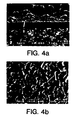
- Figure 4 is a scanning electron micrograph of a typical mullite coating on a Si 3 N 4 substrate using the above process parameters.
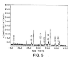
- X-ray diffraction analysis confirms that mullite is the only crystalline phase present in the coating.
- Figure 5 shows the x-ray diffraction pattern.
- the coating is uniform, with a fine grained, equiaxed structure. There is some agglomeration of grains seen on the surface. This, however is not believed to have originated from the substrate surface, but instead is believed to be formed on the surface of the coating.
- the coating appears to be very dense. Additionally, no cracks are observed on the surface of the coating.
- CVD mullite powder is synthesized from AlCl 3 -SiCl- 4 -CO 2 -H 2 mixtures.
- the parameters for synthesis are selected based upon the equilibrium thermodynamic analysis and the corresponding CVD phase diagram of Figure 3 constructed as a result of that analysis.
- the process steps for accomplishing the synthesis are the same as those described above with respect to the deposition of mullite coatings.
- the reaction is preferably performed in the reactor of Figure 1 . Again, there should be provided accurate temperature, pressure and flow controls.
- the process described above is employed in order to create a mullite powder. Parameters are selected based upon the equilibrium thermodynamic analysis and the corresponding CVD phase diagram ( Figure 3 ) discussed above. When there is no surface available for the mullite to nucleate upon, under the proper process parameters (e.g. sufficient energy and proper gas flow ratios), a mullite powder may be formed through homogeneous nucleation. This physical property forms the basis for the synthesis of mullite powder according to the second embodiment of the present invention.
- the reactor of Figure 1 is employed and an identical process as that described above is used. The process parameters, however, are different and there is no substrate placed in the CVD reactor. In the case of powder synthesis, the powder will form upon the sidewalls of the CVD reactor chamber.
- Figure 6 shows scanning electron micrographs of mullite powder observed in the CVD reactor as a result of the above-described process.
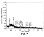
- the only crystalline phase found in the powder was mullite. This is confirmed the x-ray diffraction pattern illustrated in Figure 7 .
- the structure and composition of the powder grown according to the process of the present invention may be accurately controlled through changes in process parameters and deposition conditions. For example, it is postulated that an increased temperature will result in a larger particle size.
Landscapes
- Chemical & Material Sciences (AREA)
- Engineering & Computer Science (AREA)
- Ceramic Engineering (AREA)
- Organic Chemistry (AREA)
- Materials Engineering (AREA)
- Structural Engineering (AREA)
- Manufacturing & Machinery (AREA)
- Inorganic Chemistry (AREA)
- General Chemical & Material Sciences (AREA)
- Chemical Kinetics & Catalysis (AREA)
- Mechanical Engineering (AREA)
- Metallurgy (AREA)
- Chemical Vapour Deposition (AREA)
- Silicates, Zeolites, And Molecular Sieves (AREA)
- Compositions Of Oxide Ceramics (AREA)
Claims (20)
- Verfahren zum Abscheiden einer dichten, haftbeständigen kristallinen Mullit-Beschichtung auf einem Substrat durch chemisches Aufdampfen, das die folgenden Schritte umfasst:a) Ablegen des Substrates in einer geschlossenen Kammer;b) Einrichten eines Flusses von Al-Ausgangsgas;c) Einrichten eines Flusses von Si-Ausgangsgas;d) Mischen des Flusses des Al-Ausgangsgases mit dem Fluss des Si-Ausgangsgases;e) Einrichten eines Flusses eines Gemisches aus H2 und CO2;f) Fördern des Mischflusses der Al/Si-Ausgangsgase und des Flusses des Gemisches aus H2 und CO2 in die geschlossene Kammer;g) Einrichten eines Reaktantflusses durch Kombinieren des Mischflusses der Al/Si-Ausgangsgase und des Flusses des Gemisches aus H2 und CO2; undh) Abscheiden einer kristallinen Mullit-Schicht aus dem Reaktantfluss auf das zu beschichtende Substrat, wobei die so abgeschiedene kristalline Mullit-Schicht dicht und haftbeständig ist und das Substrat mit Hochtemperatur-Korrosionsbeständigkeit und Berührungsspannungsbeständigkeit ausstattet.
- Verfahren nach Anspruch 1, wobei das Substrat eine Silikonkeramik ist.
- Verfahren nach Anspruch 1, wobei das Substratmaterial ausgewählt ist aus Si, SiC, Si3N4, WC, WC-Co, Al2O3, SiO2, Mullit, BN, AIN oder ZrO2.
- Verfahren nach Anspruch 1, wobei das Substrat ein Verbundsubstrat auf der Basis von entweder SiC oder Si3N4 ist.
- Verfahren zum Herstellen eines feinkörnigen Pulvers aus kristallinem Mullit mit einer einheitlichen Mikrostruktur, das die folgenden Schritte umfasst:a) Einrichten eines Flusses von Al-Ausgangsgas;b) Einrichten eines Flusses von Si-Ausgangsgas;c) Mischen des Flusses des Al-Ausgangsgases mit dem Fluss des Si-Ausgangsgases;d) Einrichten eines Flusses von einem oder mehreren oxidierenden Gas(en);e) Fördern des Mischflusses der Al/Si-Ausgangsgase und des Flusses von einem oder mehreren oxidierenden Gas(en) in eine geschlossene Kammer;f) Einrichten eines Reaktantflusses durch Kombinieren des Flusses der Al/Si-Ausgangsgase und des Flusses von einem oder mehreren oxidierenden Gas(en); undg) Abscheiden eines feinkömigen Pulvers aus kristallinem Mullit aus dem Reaktantfluss in der geschlossenen Kammer.
- Verfahren nach einem der vorstehenden Ansprüche, wobei die geschlossene Kammer auf einer konstanten Temperatur im Bereich von 800°C bis 1500°C gehalten wird.
- Verfahren nach einem der vorstehenden Ansprüche, wobei die geschlossene Kammer auf einem konstanten Druck im Bereich von 0.27 g/cm2 (0.2 Torr) bis 1.033 g/cm2 (760 Torr) gehalten wird.
- Verfahren nach einem der vorstehenden Ansprüche, wobei der Fluss des Al-Ausgangsgases aus einem Al-Halogenid besteht.
- Verfahren nach Anspruch 8, wobei der Fluss des Al-Ausgangsgases aus AlCl3 besteht.
- Verfahren nach einem der vorstehenden Ansprüche, wobei der Fluss des Si-Ausgangsgases aus einem Si-Halogenid besteht.
- Verfahren nach Anspruch 10, wobei der Fluss des Si-Ausgangsgases aus SiCl4 besteht.
- Verfahren nach Anspruch 5, wobei der Fluss von einem oder mehreren oxidierenden Gas(en) aus einem Gemisch aus H2 und CO2 besteht.
- Verfahren nach einem der vorstehenden Ansprüche, wobei der Mischfluss der Al/Si-Ausgangsgase in die geschlossene Kammer mit einem Trägergas gefördert wird.
- Verfahren nach einem der vorstehenden Ansprüche, wobei das eine oder die mehreren oxierende(n) Gas(e) in die geschlossene Kammer mit einem Trägergas gefördert wird/werden.
- Verfahren nach einem der vorstehenden Ansprüche, wobei das Al/Si-Verhältnis bei ungefähr 3 zu 1 gehalten wird.
- Verfahren zum Herstellen von Mullit-Teilen, wobei das Verfahren das Herstellen von Mullit-Pulver durch ein Verfahren nach einem der Ansprüche 5 bis 15 umfasst sowie anschließend das Ausführen des Sinterns des Pulvers.
- Reaktor zum Herstellen von Mullit durch chemisches Aufdampfen (CVD), der umfasst:eine zylindrische Kammer;eine äußere Reaktantzufuhrleitung und eine innere, damit konzentrische Reaktantzufuhrleitung, wobei die Reaktantzufuhrleitungen angeordnet sind, dass sie Reaktantgase in die zylindrische Kammer fördern, und wobei diese relativ zueinander angeordnet sind, um das Mischen der Reaktantgase in der äußeren Reaktantzufuhrleitung vor dem Eintritt der Gase in die zylindrische Kammer zu erlauben;wenigstens zwei Abgasleitungen, die in der zylindrischen Kammer angeordnet sind und die derart angeordnet sind, dass sie die Reaktantzufuhrleitungen umgeben;eine Vielzahl von Probenhaltem, wobei sich jeder Probenhalter zwischen den Abgasleitungen erstreckt und durch diese gehalten wird.
- CVD-Reaktor nach Anspruch 17, wobei jede der Abgasleitungen Schlitze aufweist und wobei jeder der Vielzahl von Probenhaltem eine Kante aufweist, die angepasst ist, um zwischen die Schlitze der Abgasleitungen zu passen.
- CVD-Reaktor nach Anspruch 17 oder 18, wobei sich die Abgasleitungen von dem Boden der zylindrischen Kammer erstrecken.
- Mullit-beschichteter Gegenstand, der ein Substrat umfasst, das direkt mit einer Schicht aus dichtem, haftbeständigem Mullit beschichtet ist, die eine einheitliche Mikrostruktur und Dicke aufweist, die man durch ein Verfahren nach einem der Ansprüche 1 bis 4 erhalten kann und die das Substrat mit Hochtemperatur-Korrosionsbeständigkeit und Berührungsspannungsbeständigkeit ausstattet.
Applications Claiming Priority (3)
| Application Number | Priority Date | Filing Date | Title |
|---|---|---|---|
| US08/368,814 US5763008A (en) | 1995-01-06 | 1995-01-06 | Chemical vapor deposition of mullite coatings |
| US368814 | 1995-01-06 | ||
| PCT/US1996/000482 WO1996020903A1 (en) | 1995-01-06 | 1996-01-05 | Chemical vapor deposition of mullite coatings and powders |
Publications (2)
| Publication Number | Publication Date |
|---|---|
| EP0802892A1 EP0802892A1 (de) | 1997-10-29 |
| EP0802892B1 true EP0802892B1 (de) | 2002-04-10 |
Family
ID=23452854
Family Applications (1)
| Application Number | Title | Priority Date | Filing Date |
|---|---|---|---|
| EP96906166A Expired - Lifetime EP0802892B1 (de) | 1995-01-06 | 1996-01-05 | Chemische abscheidung von mullitschichten und mullitpulvern aus der gasphase |
Country Status (7)
| Country | Link |
|---|---|
| US (1) | US5763008A (de) |
| EP (1) | EP0802892B1 (de) |
| AT (1) | ATE215919T1 (de) |
| AU (1) | AU4963496A (de) |
| CA (1) | CA2209561A1 (de) |
| DE (1) | DE69620577T2 (de) |
| WO (1) | WO1996020903A1 (de) |
Families Citing this family (12)
| Publication number | Priority date | Publication date | Assignee | Title |
|---|---|---|---|---|
| US5869146A (en) * | 1997-11-12 | 1999-02-09 | United Technologies Corporation | Plasma sprayed mullite coatings on silicon based ceramic materials |
| US6299988B1 (en) | 1998-04-27 | 2001-10-09 | General Electric Company | Ceramic with preferential oxygen reactive layer |
| US6485848B1 (en) | 1998-04-27 | 2002-11-26 | General Electric Company | Coated article and method of making |
| US6517960B1 (en) | 1999-04-26 | 2003-02-11 | General Electric Company | Ceramic with zircon coating |
| US6485791B1 (en) * | 2000-04-06 | 2002-11-26 | Bangalore A. Nagaraj | Method for improving the performance of oxidizable ceramic materials in oxidizing environments |
| SE522735C2 (sv) * | 2001-05-30 | 2004-03-02 | Sandvik Ab | Aluminiumoxidbelagt skärverktyg |
| US6759151B1 (en) | 2002-05-22 | 2004-07-06 | The United States Of America As Represented By The Administrator Of The National Aeronautics And Space Administration | Multilayer article characterized by low coefficient of thermal expansion outer layer |
| US6733908B1 (en) | 2002-07-08 | 2004-05-11 | The United States Of America As Represented By The Administrator Of The National Aeronautics And Space Administration | Multilayer article having stabilized zirconia outer layer and chemical barrier layer |
| US7497895B2 (en) * | 2005-11-18 | 2009-03-03 | Exxonmobil Research And Engineering Company | Membrane separation process |
| US9315905B2 (en) * | 2010-03-04 | 2016-04-19 | United Technologies Corporation | Coated article and coating process therefor |
| US9581042B2 (en) | 2012-10-30 | 2017-02-28 | United Technologies Corporation | Composite article having metal-containing layer with phase-specific seed particles and method therefor |
| CN113957439B (zh) * | 2021-10-26 | 2024-01-23 | 西安热工研究院有限公司 | 一种钛合金用Al2O3_莫来石梯度防氧化涂层及其制备方法 |
Family Cites Families (14)
| Publication number | Priority date | Publication date | Assignee | Title |
|---|---|---|---|---|
| US3306768A (en) * | 1964-01-08 | 1967-02-28 | Motorola Inc | Method of forming thin oxide films |
| JPS61251588A (ja) * | 1985-04-26 | 1986-11-08 | 株式会社豊田中央研究所 | セラミツクス複合体の製造方法 |
| DE3623786A1 (de) * | 1985-11-13 | 1987-05-14 | Man Technologie Gmbh | Verfahren zur herstellung von russfiltern |
| JPS62238368A (ja) * | 1986-04-08 | 1987-10-19 | Toshiba Corp | 薄膜形成装置 |
| US5077243A (en) * | 1988-07-02 | 1991-12-31 | Noritake Co., Limited | Fiber-reinforced and particle-dispersion reinforced mullite composite material and method of producing the same |
| US4880614A (en) * | 1988-11-03 | 1989-11-14 | Allied-Signal Inc. | Ceramic thermal barrier coating with alumina interlayer |
| US5015502A (en) * | 1988-11-03 | 1991-05-14 | Allied-Signal Inc. | Ceramic thermal barrier coating with alumina interlayer |
| JP2881847B2 (ja) * | 1988-12-15 | 1999-04-12 | 日産化学工業株式会社 | コーティング用組成物及びその製造法 |
| US5322711A (en) * | 1989-07-21 | 1994-06-21 | Minnesota Mining And Manufacturing Company | Continuous method of covering inorganic fibrous material with particulates |
| US5316797A (en) * | 1990-07-13 | 1994-05-31 | General Atomics | Preparing refractory fiberreinforced ceramic composites |
| US5231061A (en) * | 1991-06-10 | 1993-07-27 | The Dow Chemical Company | Process for making coated ceramic reinforcement whiskers |
| WO1993024672A1 (en) * | 1992-05-29 | 1993-12-09 | United Technologies Corporation | Ceramic thermal barrier coating for rapid thermal cycling applications |
| DE4228711A1 (de) * | 1992-08-28 | 1994-03-03 | Degussa | Silicium-Aluminium-Mischoxid |
| US5336453B1 (en) * | 1993-06-11 | 1996-07-23 | Connecticut Innovations Inc | Method for producing ceramic-based electronic components |
-
1995
- 1995-01-06 US US08/368,814 patent/US5763008A/en not_active Expired - Lifetime
-
1996
- 1996-01-05 DE DE69620577T patent/DE69620577T2/de not_active Expired - Fee Related
- 1996-01-05 EP EP96906166A patent/EP0802892B1/de not_active Expired - Lifetime
- 1996-01-05 AT AT96906166T patent/ATE215919T1/de not_active IP Right Cessation
- 1996-01-05 WO PCT/US1996/000482 patent/WO1996020903A1/en not_active Ceased
- 1996-01-05 AU AU49634/96A patent/AU4963496A/en not_active Abandoned
- 1996-01-05 CA CA002209561A patent/CA2209561A1/en not_active Abandoned
Also Published As
| Publication number | Publication date |
|---|---|
| DE69620577D1 (de) | 2002-05-16 |
| AU4963496A (en) | 1996-07-24 |
| US5763008A (en) | 1998-06-09 |
| ATE215919T1 (de) | 2002-04-15 |
| CA2209561A1 (en) | 1996-07-11 |
| EP0802892A1 (de) | 1997-10-29 |
| WO1996020903A1 (en) | 1996-07-11 |
| DE69620577T2 (de) | 2002-09-26 |
Similar Documents
| Publication | Publication Date | Title |
|---|---|---|
| US5514350A (en) | Apparatus for making nanostructured ceramic powders and whiskers | |
| Niihara et al. | Chemical vapour-deposited silicon nitride: Part 1 Preparation and some properties | |
| US4312921A (en) | Super hard-highly pure silicon nitrides | |
| US5763008A (en) | Chemical vapor deposition of mullite coatings | |
| US5300322A (en) | Molybdenum enhanced low-temperature deposition of crystalline silicon nitride | |
| US4632849A (en) | Method for making a fine powder of a metal compound having ceramic coatings thereon | |
| US20050013993A1 (en) | Environmental & thermal barrier coating | |
| JP3971546B2 (ja) | 多孔質セラミック積層体及びその製造方法 | |
| JPH07252662A (ja) | 高純度複合材およびその製法 | |
| WO1996029445A1 (en) | Chemical vapor deposition of rhenium on carbon substrates | |
| US5693305A (en) | Method for synthesizing aluminum nitride whiskers | |
| US20060003567A1 (en) | MoSi2-SiC nanocomposite coating, and manufacturing method thereof | |
| EP3597621A1 (de) | Verfahren zur herstellung eines komplexes auf silicium-carbid-basis | |
| JP2801485B2 (ja) | 複合体およびその製法 | |
| JP2684106B2 (ja) | セラミックス被覆用黒鉛基材及びcvd炉用内部部品 | |
| US5001001A (en) | Process for the fabrication of ceramic monoliths by laser-assisted chemical vapor infiltration | |
| Scheiffarth et al. | Increasing high temperature oxidation and corrosion resistance of graphite and carbon-fiber-reinforced carbon by deposition of a low pressure chemically vapor-deposited silicon carbide coating | |
| Kato | Vapour Phase Synthesis of Ultrafine Non-oxide Powders and their Sintering Behaviour | |
| Thiel et al. | Thermal spraying of silicon nitride-based powders | |
| JP2955745B2 (ja) | 複合セラミックス及びその製造方法 | |
| JPH03271170A (ja) | 繊維強化セラミックス複合体 | |
| JPS58115011A (ja) | 超硬高純度の非晶質窒化珪素とその製造方法 | |
| JPH11293471A (ja) | Cvd法による成膜方法 | |
| Warren | Cost-Effective Low-Temperature CVD Coatings for Industrial Applications | |
| JPS5988306A (ja) | 超硬高純度窒化珪素の製造方法 |
Legal Events
| Date | Code | Title | Description |
|---|---|---|---|
| PUAI | Public reference made under article 153(3) epc to a published international application that has entered the european phase |
Free format text: ORIGINAL CODE: 0009012 |
|
| 17P | Request for examination filed |
Effective date: 19970801 |
|
| AK | Designated contracting states |
Kind code of ref document: A1 Designated state(s): AT BE CH DE DK ES FR GB GR IE IT LI LU MC NL PT SE |
|
| RIN1 | Information on inventor provided before grant (corrected) |
Inventor name: MULPURI, RAO Inventor name: SARIN, VINOD |
|
| 17Q | First examination report despatched |
Effective date: 19980130 |
|
| GRAG | Despatch of communication of intention to grant |
Free format text: ORIGINAL CODE: EPIDOS AGRA |
|
| GRAG | Despatch of communication of intention to grant |
Free format text: ORIGINAL CODE: EPIDOS AGRA |
|
| GRAH | Despatch of communication of intention to grant a patent |
Free format text: ORIGINAL CODE: EPIDOS IGRA |
|
| GRAH | Despatch of communication of intention to grant a patent |
Free format text: ORIGINAL CODE: EPIDOS IGRA |
|
| REG | Reference to a national code |
Ref country code: GB Ref legal event code: IF02 |
|
| GRAA | (expected) grant |
Free format text: ORIGINAL CODE: 0009210 |
|
| AK | Designated contracting states |
Kind code of ref document: B1 Designated state(s): AT BE CH DE DK ES FR GB GR IE IT LI LU MC NL PT SE |
|
| PG25 | Lapsed in a contracting state [announced via postgrant information from national office to epo] |
Ref country code: NL Free format text: LAPSE BECAUSE OF FAILURE TO SUBMIT A TRANSLATION OF THE DESCRIPTION OR TO PAY THE FEE WITHIN THE PRESCRIBED TIME-LIMIT Effective date: 20020410 Ref country code: LI Free format text: LAPSE BECAUSE OF FAILURE TO SUBMIT A TRANSLATION OF THE DESCRIPTION OR TO PAY THE FEE WITHIN THE PRESCRIBED TIME-LIMIT Effective date: 20020410 Ref country code: GR Free format text: LAPSE BECAUSE OF FAILURE TO SUBMIT A TRANSLATION OF THE DESCRIPTION OR TO PAY THE FEE WITHIN THE PRESCRIBED TIME-LIMIT Effective date: 20020410 Ref country code: CH Free format text: LAPSE BECAUSE OF FAILURE TO SUBMIT A TRANSLATION OF THE DESCRIPTION OR TO PAY THE FEE WITHIN THE PRESCRIBED TIME-LIMIT Effective date: 20020410 Ref country code: BE Free format text: LAPSE BECAUSE OF FAILURE TO SUBMIT A TRANSLATION OF THE DESCRIPTION OR TO PAY THE FEE WITHIN THE PRESCRIBED TIME-LIMIT Effective date: 20020410 Ref country code: AT Free format text: LAPSE BECAUSE OF FAILURE TO SUBMIT A TRANSLATION OF THE DESCRIPTION OR TO PAY THE FEE WITHIN THE PRESCRIBED TIME-LIMIT Effective date: 20020410 |
|
| REF | Corresponds to: |
Ref document number: 215919 Country of ref document: AT Date of ref document: 20020415 Kind code of ref document: T |
|
| REG | Reference to a national code |
Ref country code: CH Ref legal event code: EP |
|
| REG | Reference to a national code |
Ref country code: IE Ref legal event code: FG4D |
|
| REF | Corresponds to: |
Ref document number: 69620577 Country of ref document: DE Date of ref document: 20020516 |
|
| PG25 | Lapsed in a contracting state [announced via postgrant information from national office to epo] |
Ref country code: PT Free format text: LAPSE BECAUSE OF FAILURE TO SUBMIT A TRANSLATION OF THE DESCRIPTION OR TO PAY THE FEE WITHIN THE PRESCRIBED TIME-LIMIT Effective date: 20020710 Ref country code: DK Free format text: LAPSE BECAUSE OF FAILURE TO SUBMIT A TRANSLATION OF THE DESCRIPTION OR TO PAY THE FEE WITHIN THE PRESCRIBED TIME-LIMIT Effective date: 20020710 |
|
| ET | Fr: translation filed | ||
| NLV1 | Nl: lapsed or annulled due to failure to fulfill the requirements of art. 29p and 29m of the patents act | ||
| REG | Reference to a national code |
Ref country code: CH Ref legal event code: PL |
|
| PG25 | Lapsed in a contracting state [announced via postgrant information from national office to epo] |
Ref country code: ES Free format text: LAPSE BECAUSE OF FAILURE TO SUBMIT A TRANSLATION OF THE DESCRIPTION OR TO PAY THE FEE WITHIN THE PRESCRIBED TIME-LIMIT Effective date: 20021030 |
|
| PG25 | Lapsed in a contracting state [announced via postgrant information from national office to epo] |
Ref country code: LU Free format text: LAPSE BECAUSE OF NON-PAYMENT OF DUE FEES Effective date: 20030105 |
|
| PG25 | Lapsed in a contracting state [announced via postgrant information from national office to epo] |
Ref country code: IE Free format text: LAPSE BECAUSE OF NON-PAYMENT OF DUE FEES Effective date: 20030106 |
|
| PG25 | Lapsed in a contracting state [announced via postgrant information from national office to epo] |
Ref country code: MC Free format text: LAPSE BECAUSE OF NON-PAYMENT OF DUE FEES Effective date: 20030131 |
|
| PLBE | No opposition filed within time limit |
Free format text: ORIGINAL CODE: 0009261 |
|
| STAA | Information on the status of an ep patent application or granted ep patent |
Free format text: STATUS: NO OPPOSITION FILED WITHIN TIME LIMIT |
|
| 26N | No opposition filed |
Effective date: 20030113 |
|
| REG | Reference to a national code |
Ref country code: IE Ref legal event code: MM4A |
|
| PGFP | Annual fee paid to national office [announced via postgrant information from national office to epo] |
Ref country code: FR Payment date: 20050113 Year of fee payment: 10 |
|
| PGFP | Annual fee paid to national office [announced via postgrant information from national office to epo] |
Ref country code: GB Payment date: 20051130 Year of fee payment: 11 |
|
| PGFP | Annual fee paid to national office [announced via postgrant information from national office to epo] |
Ref country code: DE Payment date: 20060125 Year of fee payment: 11 |
|
| PGFP | Annual fee paid to national office [announced via postgrant information from national office to epo] |
Ref country code: SE Payment date: 20060127 Year of fee payment: 11 |
|
| PG25 | Lapsed in a contracting state [announced via postgrant information from national office to epo] |
Ref country code: FR Free format text: LAPSE BECAUSE OF NON-PAYMENT OF DUE FEES Effective date: 20060131 |
|
| PGFP | Annual fee paid to national office [announced via postgrant information from national office to epo] |
Ref country code: IT Payment date: 20060131 Year of fee payment: 11 |
|
| REG | Reference to a national code |
Ref country code: FR Ref legal event code: ST Effective date: 20060929 |
|
| PG25 | Lapsed in a contracting state [announced via postgrant information from national office to epo] |
Ref country code: SE Free format text: LAPSE BECAUSE OF NON-PAYMENT OF DUE FEES Effective date: 20070106 |
|
| PG25 | Lapsed in a contracting state [announced via postgrant information from national office to epo] |
Ref country code: DE Free format text: LAPSE BECAUSE OF NON-PAYMENT OF DUE FEES Effective date: 20070801 |
|
| EUG | Se: european patent has lapsed | ||
| GBPC | Gb: european patent ceased through non-payment of renewal fee |
Effective date: 20070105 |
|
| PG25 | Lapsed in a contracting state [announced via postgrant information from national office to epo] |
Ref country code: GB Free format text: LAPSE BECAUSE OF NON-PAYMENT OF DUE FEES Effective date: 20070105 |
|
| PG25 | Lapsed in a contracting state [announced via postgrant information from national office to epo] |
Ref country code: IT Free format text: LAPSE BECAUSE OF NON-PAYMENT OF DUE FEES Effective date: 20070105 |