EP0802810B1 - Injektionsvorrichtung zur Aufnahme eines flüssigen Medikaments - Google Patents
Injektionsvorrichtung zur Aufnahme eines flüssigen Medikaments Download PDFInfo
- Publication number
- EP0802810B1 EP0802810B1 EP95935793A EP95935793A EP0802810B1 EP 0802810 B1 EP0802810 B1 EP 0802810B1 EP 95935793 A EP95935793 A EP 95935793A EP 95935793 A EP95935793 A EP 95935793A EP 0802810 B1 EP0802810 B1 EP 0802810B1
- Authority
- EP
- European Patent Office
- Prior art keywords
- injection device
- lower portion
- container
- kinematic
- individual steps
- Prior art date
- Legal status (The legal status is an assumption and is not a legal conclusion. Google has not performed a legal analysis and makes no representation as to the accuracy of the status listed.)
- Expired - Lifetime
Links
- 238000002347 injection Methods 0.000 title claims abstract description 23
- 239000007924 injection Substances 0.000 title claims abstract description 23
- 239000003814 drug Substances 0.000 title claims abstract description 21
- 239000007788 liquid Substances 0.000 title claims abstract description 16
- 239000003708 ampul Substances 0.000 claims abstract description 15
- 229940079593 drug Drugs 0.000 claims description 16
- 230000008878 coupling Effects 0.000 claims description 6
- 238000010168 coupling process Methods 0.000 claims description 6
- 238000005859 coupling reaction Methods 0.000 claims description 6
- 239000000463 material Substances 0.000 claims description 3
- 230000006835 compression Effects 0.000 claims 1
- 238000007906 compression Methods 0.000 claims 1
- 238000012544 monitoring process Methods 0.000 claims 1
- 238000000034 method Methods 0.000 description 2
- 238000010276 construction Methods 0.000 description 1
- 230000001419 dependent effect Effects 0.000 description 1
- 238000011161 development Methods 0.000 description 1
- 230000018109 developmental process Effects 0.000 description 1
- 238000012377 drug delivery Methods 0.000 description 1
- 238000005516 engineering process Methods 0.000 description 1
- 230000007613 environmental effect Effects 0.000 description 1
- 230000007257 malfunction Effects 0.000 description 1
- 239000002184 metal Substances 0.000 description 1
- 238000011002 quantification Methods 0.000 description 1
- 238000004064 recycling Methods 0.000 description 1
- 239000000243 solution Substances 0.000 description 1
- 238000002560 therapeutic procedure Methods 0.000 description 1
Images
Classifications
-
- A—HUMAN NECESSITIES
- A61—MEDICAL OR VETERINARY SCIENCE; HYGIENE
- A61M—DEVICES FOR INTRODUCING MEDIA INTO, OR ONTO, THE BODY; DEVICES FOR TRANSDUCING BODY MEDIA OR FOR TAKING MEDIA FROM THE BODY; DEVICES FOR PRODUCING OR ENDING SLEEP OR STUPOR
- A61M5/00—Devices for bringing media into the body in a subcutaneous, intra-vascular or intramuscular way; Accessories therefor, e.g. filling or cleaning devices, arm-rests
- A61M5/178—Syringes
- A61M5/31—Details
- A61M5/315—Pistons; Piston-rods; Guiding, blocking or restricting the movement of the rod or piston; Appliances on the rod for facilitating dosing ; Dosing mechanisms
- A61M5/31565—Administration mechanisms, i.e. constructional features, modes of administering a dose
- A61M5/31576—Constructional features or modes of drive mechanisms for piston rods
- A61M5/31578—Constructional features or modes of drive mechanisms for piston rods based on axial translation, i.e. components directly operatively associated and axially moved with plunger rod
- A61M5/3158—Constructional features or modes of drive mechanisms for piston rods based on axial translation, i.e. components directly operatively associated and axially moved with plunger rod performed by axially moving actuator operated by user, e.g. an injection button
-
- A—HUMAN NECESSITIES
- A61—MEDICAL OR VETERINARY SCIENCE; HYGIENE
- A61M—DEVICES FOR INTRODUCING MEDIA INTO, OR ONTO, THE BODY; DEVICES FOR TRANSDUCING BODY MEDIA OR FOR TAKING MEDIA FROM THE BODY; DEVICES FOR PRODUCING OR ENDING SLEEP OR STUPOR
- A61M5/00—Devices for bringing media into the body in a subcutaneous, intra-vascular or intramuscular way; Accessories therefor, e.g. filling or cleaning devices, arm-rests
- A61M5/178—Syringes
- A61M5/24—Ampoule syringes, i.e. syringes with needle for use in combination with replaceable ampoules or carpules, e.g. automatic
-
- A—HUMAN NECESSITIES
- A61—MEDICAL OR VETERINARY SCIENCE; HYGIENE
- A61M—DEVICES FOR INTRODUCING MEDIA INTO, OR ONTO, THE BODY; DEVICES FOR TRANSDUCING BODY MEDIA OR FOR TAKING MEDIA FROM THE BODY; DEVICES FOR PRODUCING OR ENDING SLEEP OR STUPOR
- A61M5/00—Devices for bringing media into the body in a subcutaneous, intra-vascular or intramuscular way; Accessories therefor, e.g. filling or cleaning devices, arm-rests
- A61M5/178—Syringes
- A61M5/31—Details
- A61M5/315—Pistons; Piston-rods; Guiding, blocking or restricting the movement of the rod or piston; Appliances on the rod for facilitating dosing ; Dosing mechanisms
- A61M5/31533—Dosing mechanisms, i.e. setting a dose
- A61M5/31545—Setting modes for dosing
- A61M5/31548—Mechanically operated dose setting member
- A61M5/3155—Mechanically operated dose setting member by rotational movement of dose setting member, e.g. during setting or filling of a syringe
- A61M5/31553—Mechanically operated dose setting member by rotational movement of dose setting member, e.g. during setting or filling of a syringe without axial movement of dose setting member
-
- A—HUMAN NECESSITIES
- A61—MEDICAL OR VETERINARY SCIENCE; HYGIENE
- A61M—DEVICES FOR INTRODUCING MEDIA INTO, OR ONTO, THE BODY; DEVICES FOR TRANSDUCING BODY MEDIA OR FOR TAKING MEDIA FROM THE BODY; DEVICES FOR PRODUCING OR ENDING SLEEP OR STUPOR
- A61M5/00—Devices for bringing media into the body in a subcutaneous, intra-vascular or intramuscular way; Accessories therefor, e.g. filling or cleaning devices, arm-rests
- A61M5/178—Syringes
- A61M5/24—Ampoule syringes, i.e. syringes with needle for use in combination with replaceable ampoules or carpules, e.g. automatic
- A61M2005/2485—Ampoule holder connected to rest of syringe
- A61M2005/2488—Ampoule holder connected to rest of syringe via rotation, e.g. threads or bayonet
-
- A—HUMAN NECESSITIES
- A61—MEDICAL OR VETERINARY SCIENCE; HYGIENE
- A61M—DEVICES FOR INTRODUCING MEDIA INTO, OR ONTO, THE BODY; DEVICES FOR TRANSDUCING BODY MEDIA OR FOR TAKING MEDIA FROM THE BODY; DEVICES FOR PRODUCING OR ENDING SLEEP OR STUPOR
- A61M5/00—Devices for bringing media into the body in a subcutaneous, intra-vascular or intramuscular way; Accessories therefor, e.g. filling or cleaning devices, arm-rests
- A61M5/14—Infusion devices, e.g. infusing by gravity; Blood infusion; Accessories therefor
- A61M5/142—Pressure infusion, e.g. using pumps
- A61M5/145—Pressure infusion, e.g. using pumps using pressurised reservoirs, e.g. pressurised by means of pistons
- A61M5/1452—Pressure infusion, e.g. using pumps using pressurised reservoirs, e.g. pressurised by means of pistons pressurised by means of pistons
- A61M5/1456—Pressure infusion, e.g. using pumps using pressurised reservoirs, e.g. pressurised by means of pistons pressurised by means of pistons with a replaceable reservoir comprising a piston rod to be moved into the reservoir, e.g. the piston rod is part of the removable reservoir
-
- A—HUMAN NECESSITIES
- A61—MEDICAL OR VETERINARY SCIENCE; HYGIENE
- A61M—DEVICES FOR INTRODUCING MEDIA INTO, OR ONTO, THE BODY; DEVICES FOR TRANSDUCING BODY MEDIA OR FOR TAKING MEDIA FROM THE BODY; DEVICES FOR PRODUCING OR ENDING SLEEP OR STUPOR
- A61M5/00—Devices for bringing media into the body in a subcutaneous, intra-vascular or intramuscular way; Accessories therefor, e.g. filling or cleaning devices, arm-rests
- A61M5/178—Syringes
- A61M5/31—Details
- A61M5/315—Pistons; Piston-rods; Guiding, blocking or restricting the movement of the rod or piston; Appliances on the rod for facilitating dosing ; Dosing mechanisms
- A61M5/31533—Dosing mechanisms, i.e. setting a dose
- A61M5/31545—Setting modes for dosing
- A61M5/31548—Mechanically operated dose setting member
- A61M5/31561—Mechanically operated dose setting member using freely adjustable volume steps
-
- A—HUMAN NECESSITIES
- A61—MEDICAL OR VETERINARY SCIENCE; HYGIENE
- A61M—DEVICES FOR INTRODUCING MEDIA INTO, OR ONTO, THE BODY; DEVICES FOR TRANSDUCING BODY MEDIA OR FOR TAKING MEDIA FROM THE BODY; DEVICES FOR PRODUCING OR ENDING SLEEP OR STUPOR
- A61M5/00—Devices for bringing media into the body in a subcutaneous, intra-vascular or intramuscular way; Accessories therefor, e.g. filling or cleaning devices, arm-rests
- A61M5/178—Syringes
- A61M5/31—Details
- A61M5/315—Pistons; Piston-rods; Guiding, blocking or restricting the movement of the rod or piston; Appliances on the rod for facilitating dosing ; Dosing mechanisms
- A61M5/31565—Administration mechanisms, i.e. constructional features, modes of administering a dose
- A61M5/3159—Dose expelling manners
- A61M5/31593—Multi-dose, i.e. individually set dose repeatedly administered from the same medicament reservoir
Definitions
- the invention relates to an injection device for Admission of a liquid medication according to the generic term of claim 1.
- injection pens or “Pens” for short, because of their specific shape and Analogy to a pen.
- Examples of devices according to the first group - which are intended for single use - are detailed in the Documents EP-B 327 910, EP-A 594 349 EP-A 496 141 and US 5 295 976 described.
- the ampoule is what contains the liquid medication, directly in the "injection pen” installed and is delivered to the patient as a unit.
- these Thrown away everything because of the more complicated parts of the "Pens” which e.g. also a metering and counting device can include, is quite expensive.
- Devices this Groups are therefore very expensive and also offer no solution for the recycling of individual parts, because of the various materials that are used for this.
- Examples of devices of the second group - which can be reused - are detailed in the Documents DE-C 36 38 984, EP-A 498 737 and US 4,883,472 described. In these devices, the exhausted Ampoule to be replaced with a fresh one.
- the exchange procedure for Ampoule quite complicated. To put a new ampoule in the To use the device, its propulsion mechanism must be in a defined starting point can be brought back (e.g. by Turn back the threaded piston rod). Around The patient must be able to carry out this procedure safely be carefully instructed accordingly. Another The disadvantage is the risk of malfunction of the Dosing mechanism, since this very soon due to the frequent Use becomes worn.
- the invention seeks to remedy this.
- the invention lies based on the task, the above disadvantages of the state overcoming technology.
- the invention solves the problem with a Injection device having the features of claim 1 having.
- the lower, disposable part includes those Elements that either wear out during use or which are less complicated and therefore less are expensive, e.g. as plastic parts Ampoule holder for holding a container of the liquid drug; one Needle holder, one Ratchet, one Threaded nut and one threaded piston rod, and as Metal parts one Spring, which is mounted around the piston rod and presses against the threaded nut to make it axial Hold position.
- the upper, reusable part includes those elements which are not exhausted during use or which are complicated and / or expensive, e.g. one rotatable dosing button Coupling element for transmitting the rotation the dosing button on the threaded nut a housing, which is detachably on the lower part can be attached (not shown in the drawing)
- Counting device to measure the amount of liquid medication to capture and a mechanical fuse.
- the patient receives the device according to the invention in a two-part form, which he can assemble before use. For this purpose, he only needs to click or screw the lower, disposable part onto the upper, reusable part. After the ampoule containing the liquid medication is exhausted, the patient can throw away the entire lower part and couple a new, lower part to the reusable, upper part, which contains the valuable elements of the "injection pen" and can be reused for several years .
- the lower part preferably consists entirely of recyclable materials, so that the environmental impact can be kept to a minimum.
- An important advantage of the device according to the invention there is the possibility of paralleling the upper part Dispensing several different types of medication to use. Another advantage is the reliable quantification drug delivery.
- a quarter one full rotation of a cam of the safety device can correspond to which a turning backwards of the dosing button prevented.
- the maximum dose per injection is given by the maximum stroke of the dosing button determined. Therefore the Medication dose for a specific therapy by the lower, disposable part of the device according to the invention predetermined. Therefore the upper part is with the Dosing unit for a simple adjustment and ejection mechanism reduced, which if necessary by a counting mechanism can be supplemented by what rotational movements (e.g. quarter turns).
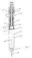
- the injection device according to the invention shown in FIG. 1 consists of a lower part 1 and an upper part Part 9 which by means of a threaded connection 13 or Bayonet lock are coupled together.
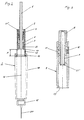
- the lower Part 1 is in Fig. 2 and the upper part in Fig. 3 in each decoupled state shown.
- the Container 14 which can consist of an ampoule, is on its rear end by an axially movable plug 15 closed.
- a non-rotatable, but axial displaceable piston rod 5 is in the longitudinal axis 16 of the Injection device arranged in alignment and can by means their front plate 17 act on the plug 15.
- the Piston rod 5 has a non-circular cross section so that it is not rotatable.
- the threaded nut 4 surrounds the Piston rod 5, the two elements 4.5 as Spindle / nut device act. For this purpose the Threaded nut 4 an internal thread, which the thread of Piston rod 5 corresponds.
- the threaded nut 4 is connected to a pipe 3 surrounding it, in which a spring 6 is accommodated, which holds the threaded nut 4 in its axial position.
- the spring 6 is secured at its lower end by the tube 3, the diameter of which is reduced there accordingly. This construction guarantees that the spring 6 also rotates when the threaded nut 4 rotates, since the threaded nut 4 is connected to the tube 3 in a rotationally fixed but axially displaceable manner.
- the threaded nut 4 is secured at its upper end by a flange 2. At the lower end of the tube 3, a ratchet 22 is attached, which will be described in more detail below.
- the functioning of the injection system is described below, starting from the rest position shown in FIG. 1.
- the user turns the knob 8 and transmits it the rotation on the hollow cylinder 7, which by means of Couplings 21 'and 21' 'rotatable on the threaded nut 4 is coupled. Since the threaded nut 4 by the spring 6 in is held in its axial position, there is an axial Forward movement of the piston rod 5 by the rotation of the Thread nut 4.
- the number of turns N (e.g. Quarter turns) of the button 8 is by a suitable-drawing not shown - counting mechanism detected, which works either mechanically or electronically.
- the ratchet 22 Reverse lock at the lower end of tube 3) acoustic or tactile signal, e.g. after every quarter turn button 8.
- the front panel 17 turns moves the corresponding amount Nz closer to the plug 15, where z corresponds to the predeterminable number of discrete steps.
- knob 8 If the knob 8 is not turned at all, there is no Ejection of medication liquid because the front panel 17 the stopper 15 only after complete replacement Stroke length H touches.
- button .8 is in its entire stroke length H down is pressed, it is by a fuse 10 by means of Leaf spring 11 held in its end position like this Fig. 3 can be seen.
Landscapes
- Health & Medical Sciences (AREA)
- Vascular Medicine (AREA)
- Engineering & Computer Science (AREA)
- Anesthesiology (AREA)
- Biomedical Technology (AREA)
- Heart & Thoracic Surgery (AREA)
- Hematology (AREA)
- Life Sciences & Earth Sciences (AREA)
- Animal Behavior & Ethology (AREA)
- General Health & Medical Sciences (AREA)
- Public Health (AREA)
- Veterinary Medicine (AREA)
- Infusion, Injection, And Reservoir Apparatuses (AREA)
Description
Nach Erschöpfung der Ampulle, welche das flüssige Medikament enthält, kann der Patient den gesamten unteren Teil wegwerfen und einen neuen, unteren Teil an den wiederverwendbaren, oberen Teil ankuppeln, welcher die wertvollen Elemente des "injection pen" enthält und während mehrerer Jahre wiederverwendet werden kann. Vorzugsweise besteht der untere Teil vollständig aus rezyklierbaren Materialien, so dass die Umweltbelastung minimal gehalten werden kann.
Die Gewindemutter 4 ist an ihrem oberen Ende durch einen Flansch 2 gesichert. Am unteren Ende des Rohres 3 ist eine Ratsche 22 angebracht, welche weiter unten noch im Detail beschrieben wird.
Claims (8)
- Injektionsvorrichtung zur Aufnahme eines flüssigen Medikamentes, welches mittels einer Nadel (20) in den menschlichen oder tierischen Körper injizierbar ist, umfassend:einen Ampullenhalter (18) zur Aufnahme eines, das flüssige Medikament enthaltenden, Behälters (14), welcher einen axial beweglichen Stopfen (15) vom Querschnitt F aufweist, zur Ausstossung des flüssigen Medikamentes aus dem Behälter (14);eine kinematische Vorrichtung zum axialen Vortrieb des Stopfens (15) über eine Anzahl N von Einzelschritten z, wobei die Anzahl N eine natürliche Zahl bedeutet;ein lösbar mit dem Ampullenhalter (18) verbindbares Gehäuse mit einem rotierbaren und über eine vorbestimmte Hublänge längsverschieblichen Dosierknopf (8) zur Auswahl der Anzahl N von Einzelschritten z und mit einstückig mit dem Dosierknopf (8) verbundenen Mitteln (7) zur Betätigung der kinematischen Vorrichtung, wodurch eine wählbare Ausstossung eines Volumens V = N x z x F des flüssigen Medikamentes aus dem Behälter (14) bewirkbar ist, dadurch gekennzeichnet, dass der Ampullenhalter (18) einen unteren, wegwerfbaren Teil (1) bildet, die kinematische Vorrichtung im unteren Teil (1) angeordnet ist , und das Gehäuse einen oberen, wiederverwendbaren Teil (9) bildet.
- Injektionsvorrichtung nach Anspruch 1, dadurch gekennzeichnet, dass die kinematische Vorrichtung nur in einer Richtung bewegbar ist und zwar vom oberen Teil (9) zum unteren Teil (1).
- Injektionsvorrichtung nach Anspruch 1 oder 2, dadurch gekennzeichnet, dass die kinematische Vorrichtung des unteren Teils (1) zusätzlich die folgenden Teile umfasst:eine rotationsfeste, aber axial bewegliche Kolbenstange (5), welche auf den Stopfen (15) des Behälters (14) wirkt;ein auf der Kolbenstange (5) angebrachtes Aussengewinde (23);eine Gewindemutter (4) mit einem Innengewinde, welches mit dem Aussengewinde (23) zusammenwirkt.
- Injektionsvorrichtung nach einem der Ansprüche 1 - 3, dadurch gekennzeichnet, dass sowohl der untere Teil (1) als auch der obere Teil (9) mit Kupplungsmitteln zur gegenseitigen lösbaren Fixierung versehen sind.
- Injektionsvorrichtung nach einem der Ansprüche 1 - 4,
dadurch gekennzeichnet, dass die mit dem rotierbaren Dosierknopf (8) verbundenen Mittel (7)
ein Kupplungselement (21') zur Übertragung der Rotation des Dosierknopfes (8) zur kinematischen Vorrichtung des unteren Teils (1) aufweisen. - Injektionsvorrichtung nach einem der Ansprüche 3 - 5, dadurch gekennzeichnet, dass der untere Teil (1) zusätzlich eine Feder (6) umfasst, welche um die Kolbenstange (5) herum angeordnet ist und durch ihre Kompression die Gewindemutter (4) in ihrer axialen Position festhält.
- Injektionsvorrichtung nach einem der Ansprüche 1 - 6, dadurch gekennzeichnet, dass am Dosierknopf (8) oder den damit verbundenen Mittel (7) zusätzlich ein elektronischer oder mechanischer Zähler zur Auswahl und Überwachung der Anzahl N von Einzelschritten z angeordnet ist.
- Injektionsvorrichtung nach einem der Ansprüche 1 - 7, dadurch gekennzeichnet, dass der untere Teil (1) vollständig aus rezyklierbarem Material besteht.
Applications Claiming Priority (1)
| Application Number | Priority Date | Filing Date | Title |
|---|---|---|---|
| PCT/CH1995/000261 WO1997017095A1 (de) | 1995-11-09 | 1995-11-09 | Injektionsvorrichtung zur aufnahme eines flüssigen medikamentes |
Publications (2)
| Publication Number | Publication Date |
|---|---|
| EP0802810A1 EP0802810A1 (de) | 1997-10-29 |
| EP0802810B1 true EP0802810B1 (de) | 2001-10-10 |
Family
ID=4549987
Family Applications (1)
| Application Number | Title | Priority Date | Filing Date |
|---|---|---|---|
| EP95935793A Expired - Lifetime EP0802810B1 (de) | 1995-11-09 | 1995-11-09 | Injektionsvorrichtung zur Aufnahme eines flüssigen Medikaments |
Country Status (7)
| Country | Link |
|---|---|
| US (1) | US6059755A (de) |
| EP (1) | EP0802810B1 (de) |
| JP (1) | JP3739406B2 (de) |
| AT (1) | ATE206625T1 (de) |
| DE (1) | DE59509694D1 (de) |
| DK (1) | DK0802810T3 (de) |
| WO (1) | WO1997017095A1 (de) |
Families Citing this family (27)
| Publication number | Priority date | Publication date | Assignee | Title |
|---|---|---|---|---|
| FR2756811B1 (fr) * | 1996-12-06 | 1999-02-05 | Valois | Dispositif de distribution de produit fluide du type bicomposant |
| DE19723647C1 (de) | 1997-06-05 | 1998-12-24 | Disetronic Licensing Ag | Rücksetzbare Anzeigeeinrichtung einer Vorrichtung zur dosierten Abgabe eines Medikamentfluids |
| US5921966A (en) * | 1997-08-11 | 1999-07-13 | Becton Dickinson And Company | Medication delivery pen having an improved clutch assembly |
| US6673049B2 (en) | 2001-02-15 | 2004-01-06 | Disetronic Licensing Ag | Injection device for injecting fluid |
| SE518708C2 (sv) * | 2001-02-28 | 2002-11-12 | Mats Bonniers Sjukvaard Och Ut | Injektionsspruta med doseringsanordning |
| DE20112501U1 (de) * | 2001-07-30 | 2002-12-19 | Disetronic Licensing Ag, Burgdorf | Verriegelungssperre für eine Verbindung von Gehäuseteilen eines Injektions- oder Infusionsgeräts |
| DE10163325B4 (de) | 2001-07-30 | 2005-07-28 | Tecpharma Licensing Ag | Verriegelungssperre für eine Verbindung von Gehäuseabschnitten eines Verabreichungsgeräts |
| DE10163328B4 (de) * | 2001-07-30 | 2005-08-11 | Tecpharma Licensing Ag | Verabreichungsgerät mit Verdrehsicherung |
| DE10163327A1 (de) * | 2001-07-30 | 2003-02-27 | Disetronic Licensing Ag | Reservoirmodul mit Kolbenstange |
| DE10163326A1 (de) | 2001-07-30 | 2003-02-27 | Disetronic Licensing Ag | Verabreichungsgerät mit Dosiervorrichtung |
| FR2829690B1 (fr) * | 2001-09-19 | 2003-12-19 | Inoteb | Dispositif de mise en place d'un biomateriau |
| DE20209051U1 (de) | 2001-12-21 | 2003-04-24 | Disetronic Licensing Ag, Burgdorf | Injektionsgerät mit endpositionsblockiertem Dosiseinstellglied |
| GB0200444D0 (en) | 2002-01-10 | 2002-02-27 | Owen Mumford Ltd | Improvements relating to medical injection devices |
| GB0304823D0 (en) | 2003-03-03 | 2003-04-09 | Dca Internat Ltd | Improvements in and relating to a pen-type injector |
| GB0304822D0 (en) | 2003-03-03 | 2003-04-09 | Dca Internat Ltd | Improvements in and relating to a pen-type injector |
| US20050222539A1 (en) * | 2004-03-30 | 2005-10-06 | Pediamed Pharmaceuticals, Inc. | Automatic injection device |
| DE102004059126B4 (de) * | 2004-12-08 | 2014-01-16 | Roche Diagnostics Gmbh | Adapter für Injektionsgerät |
| DE102006038121A1 (de) * | 2006-08-14 | 2008-02-21 | Tecpharma Licensing Ag | Injektionsvorrichtung mit Echtzeitanzeige |
| WO2008055689A1 (en) * | 2006-11-10 | 2008-05-15 | Roche Diagnostics Gmbh | Container for receiving medical liquids |
| DE102007026083A1 (de) | 2007-05-25 | 2008-11-27 | Haselmeier S.A.R.L. | Injektionsgerät |
| CH700630A1 (de) * | 2009-03-18 | 2010-09-30 | Tecpharma Licensing Ag | Verabreichungsvorrichtung mit hydraulischer Kraftübertragung. |
| CH700643A1 (de) * | 2009-03-20 | 2010-09-30 | Tecpharma Licensing Ag | Verabreichungsvorrichtung mit auswechselbarer Produkteinheit. |
| WO2010115818A1 (en) * | 2009-03-31 | 2010-10-14 | Sanofi-Aventis Deutschland Gmbh | Drug delivery device |
| DE102009003721A1 (de) * | 2009-04-01 | 2010-10-07 | Medimatik Gmbh | Applikationsgerät |
| US9265891B2 (en) * | 2009-09-30 | 2016-02-23 | Sanofi-Aventis Deutschland Gmbh | Assembly of a drug delivery device |
| US10010678B2 (en) | 2010-03-31 | 2018-07-03 | Emperra Gmbh E-Health Technologies | Assembly to administer insulin from a cartridge |
| EP2981311B1 (de) * | 2013-04-05 | 2018-06-13 | Novo Nordisk A/S | Arzneimittelabgabevorrichtung mit magnetischem bewegungsanzeiger |
Family Cites Families (6)
| Publication number | Priority date | Publication date | Assignee | Title |
|---|---|---|---|---|
| GB2109690B (en) * | 1981-02-12 | 1985-02-20 | Robert Charles Turner | Dose metering plunger devices for use with syringes |
| GB8713810D0 (en) * | 1987-06-12 | 1987-07-15 | Hypoguard Uk Ltd | Measured dose dispensing device |
| DE69203472T2 (de) * | 1991-02-07 | 1996-01-04 | Terumo Corp | Dosiereinrichtung für Injektor. |
| CH682806A5 (de) * | 1992-02-21 | 1993-11-30 | Medimpex Ets | Injektionsgerät. |
| US5545147A (en) * | 1992-10-20 | 1996-08-13 | Eli Lilly And Company | Anti-backup improvement for hypodermic syringes |
| SE9301494D0 (sv) * | 1993-04-30 | 1993-04-30 | Kabi Pharmacia Ab | A device for dosing liquid preparation |
-
1995
- 1995-11-09 DK DK95935793T patent/DK0802810T3/da active
- 1995-11-09 US US08/860,936 patent/US6059755A/en not_active Expired - Lifetime
- 1995-11-09 AT AT95935793T patent/ATE206625T1/de not_active IP Right Cessation
- 1995-11-09 EP EP95935793A patent/EP0802810B1/de not_active Expired - Lifetime
- 1995-11-09 DE DE59509694T patent/DE59509694D1/de not_active Expired - Lifetime
- 1995-11-09 WO PCT/CH1995/000261 patent/WO1997017095A1/de not_active Ceased
- 1995-11-09 JP JP52152097A patent/JP3739406B2/ja not_active Expired - Fee Related
Also Published As
| Publication number | Publication date |
|---|---|
| ATE206625T1 (de) | 2001-10-15 |
| DE59509694D1 (de) | 2001-11-15 |
| DK0802810T3 (da) | 2001-11-26 |
| JP3739406B2 (ja) | 2006-01-25 |
| EP0802810A1 (de) | 1997-10-29 |
| JPH11502145A (ja) | 1999-02-23 |
| US6059755A (en) | 2000-05-09 |
| WO1997017095A1 (de) | 1997-05-15 |
Similar Documents
| Publication | Publication Date | Title |
|---|---|---|
| EP0802810B1 (de) | Injektionsvorrichtung zur Aufnahme eines flüssigen Medikaments | |
| DE60204422T3 (de) | Automatische einspritzeinheit mit rücksetzeigenschaft | |
| DE69302625T2 (de) | Medikamentenspender | |
| EP3590569B1 (de) | Vorrichtung zur dosierten verabreichung eines fluiden produkts mit entkopplung für einen behältniswechsel | |
| DE10351596B4 (de) | Autoinjektor mit variabler Dosis | |
| EP0581788B1 (de) | Injektionsgerät | |
| DE69729300T2 (de) | Dosiervorrichtung | |
| DE60021425T2 (de) | Dosierungsbegrenzer | |
| EP2644218B2 (de) | Injektionsvorrichtung mit Dosisanzeige und Federantrieb | |
| EP2252351B1 (de) | Verabreichungsvorrichtung mit halteeinrichtung | |
| EP0848624A1 (de) | Injektionsgerät zum injizieren von flüssigkeit | |
| EP0642802A2 (de) | Inhalationsgerät | |
| DE202010018495U1 (de) | Anzeigemechanismus für einen automatischen Applikator, insbesondere für Insulin | |
| EP1525015A1 (de) | Verabreichungsgerät mit primingfunktion | |
| CH658995A5 (de) | Zahnaerztliches allzweckabgabesystem. | |
| EP0268191A2 (de) | Injektionsgerät | |
| DE10229138A1 (de) | Produktausschüttvorrichtung mit Kolbenstangen-Eilrücksetzung | |
| DE2340379A1 (de) | Geraet zur dosierenden abgabe von paste oder vergleichbaren massen | |
| EP2076303A1 (de) | Injektionsgerät mit mehreren kupplungen | |
| DE10163325A1 (de) | Verriegelungssperre für eine Verbindung von Gehäuseabschnitten eines Verabreichungsgeräts | |
| EP2013589A2 (de) | Applikator mit auswechselbarem behälter | |
| DE69230317T2 (de) | Verfahren und vorrichtung zum dosieren eines flüssigen arzneimittels | |
| EP2692376B1 (de) | Injektionsvorrichtung mit einer helix- bzw. wendelförmigen Dosisskala | |
| EP3263159B1 (de) | Injektionsvorrichtung it einem dosierglied und einer vorgespannten ausschüttfeder | |
| WO2010105376A1 (de) | Verabreichungsvorrichtung mit auswechselbarer produkteinheit |
Legal Events
| Date | Code | Title | Description |
|---|---|---|---|
| PUAI | Public reference made under article 153(3) epc to a published international application that has entered the european phase |
Free format text: ORIGINAL CODE: 0009012 |
|
| AK | Designated contracting states |
Kind code of ref document: A1 Designated state(s): AT BE CH DE DK ES FR GB GR IE IT LI LU MC NL PT SE |
|
| 17P | Request for examination filed |
Effective date: 19971117 |
|
| 17Q | First examination report despatched |
Effective date: 19990413 |
|
| RTI1 | Title (correction) |
Free format text: INJECTION DEVICE FOR A LIQUID MEDICAMENT |
|
| GRAG | Despatch of communication of intention to grant |
Free format text: ORIGINAL CODE: EPIDOS AGRA |
|
| GRAG | Despatch of communication of intention to grant |
Free format text: ORIGINAL CODE: EPIDOS AGRA |
|
| GRAH | Despatch of communication of intention to grant a patent |
Free format text: ORIGINAL CODE: EPIDOS IGRA |
|
| GRAH | Despatch of communication of intention to grant a patent |
Free format text: ORIGINAL CODE: EPIDOS IGRA |
|
| GRAA | (expected) grant |
Free format text: ORIGINAL CODE: 0009210 |
|
| AK | Designated contracting states |
Kind code of ref document: B1 Designated state(s): AT BE CH DE DK ES FR GB GR IE IT LI LU MC NL PT SE |
|
| PG25 | Lapsed in a contracting state [announced via postgrant information from national office to epo] |
Ref country code: NL Free format text: LAPSE BECAUSE OF FAILURE TO SUBMIT A TRANSLATION OF THE DESCRIPTION OR TO PAY THE FEE WITHIN THE PRESCRIBED TIME-LIMIT Effective date: 20011010 Ref country code: IT Free format text: LAPSE BECAUSE OF FAILURE TO SUBMIT A TRANSLATION OF THE DESCRIPTION OR TO PAY THE FEE WITHIN THE PRESCRIBED TIME-LIMIT;WARNING: LAPSES OF ITALIAN PATENTS WITH EFFECTIVE DATE BEFORE 2007 MAY HAVE OCCURRED AT ANY TIME BEFORE 2007. THE CORRECT EFFECTIVE DATE MAY BE DIFFERENT FROM THE ONE RECORDED. Effective date: 20011010 Ref country code: IE Free format text: LAPSE BECAUSE OF FAILURE TO SUBMIT A TRANSLATION OF THE DESCRIPTION OR TO PAY THE FEE WITHIN THE PRESCRIBED TIME-LIMIT Effective date: 20011010 |
|
| REF | Corresponds to: |
Ref document number: 206625 Country of ref document: AT Date of ref document: 20011015 Kind code of ref document: T |
|
| REG | Reference to a national code |
Ref country code: CH Ref legal event code: EP |
|
| PG25 | Lapsed in a contracting state [announced via postgrant information from national office to epo] |
Ref country code: MC Free format text: LAPSE BECAUSE OF NON-PAYMENT OF DUE FEES Effective date: 20011109 Ref country code: LU Free format text: LAPSE BECAUSE OF NON-PAYMENT OF DUE FEES Effective date: 20011109 Ref country code: AT Free format text: LAPSE BECAUSE OF NON-PAYMENT OF DUE FEES Effective date: 20011109 |
|
| REG | Reference to a national code |
Ref country code: IE Ref legal event code: FG4D Free format text: GERMAN |
|
| REF | Corresponds to: |
Ref document number: 59509694 Country of ref document: DE Date of ref document: 20011115 |
|
| REG | Reference to a national code |
Ref country code: DK Ref legal event code: T3 |
|
| PG25 | Lapsed in a contracting state [announced via postgrant information from national office to epo] |
Ref country code: BE Free format text: LAPSE BECAUSE OF NON-PAYMENT OF DUE FEES Effective date: 20011130 |
|
| REG | Reference to a national code |
Ref country code: GB Ref legal event code: IF02 |
|
| PG25 | Lapsed in a contracting state [announced via postgrant information from national office to epo] |
Ref country code: SE Free format text: LAPSE BECAUSE OF FAILURE TO SUBMIT A TRANSLATION OF THE DESCRIPTION OR TO PAY THE FEE WITHIN THE PRESCRIBED TIME-LIMIT Effective date: 20020110 Ref country code: PT Free format text: LAPSE BECAUSE OF FAILURE TO SUBMIT A TRANSLATION OF THE DESCRIPTION OR TO PAY THE FEE WITHIN THE PRESCRIBED TIME-LIMIT Effective date: 20020110 |
|
| PG25 | Lapsed in a contracting state [announced via postgrant information from national office to epo] |
Ref country code: GR Free format text: LAPSE BECAUSE OF FAILURE TO SUBMIT A TRANSLATION OF THE DESCRIPTION OR TO PAY THE FEE WITHIN THE PRESCRIBED TIME-LIMIT Effective date: 20020111 |
|
| GBT | Gb: translation of ep patent filed (gb section 77(6)(a)/1977) |
Effective date: 20020105 |
|
| NLV1 | Nl: lapsed or annulled due to failure to fulfill the requirements of art. 29p and 29m of the patents act | ||
| ET | Fr: translation filed | ||
| PG25 | Lapsed in a contracting state [announced via postgrant information from national office to epo] |
Ref country code: ES Free format text: LAPSE BECAUSE OF FAILURE TO SUBMIT A TRANSLATION OF THE DESCRIPTION OR TO PAY THE FEE WITHIN THE PRESCRIBED TIME-LIMIT Effective date: 20020430 |
|
| BERE | Be: lapsed |
Owner name: DISETRONIC LICENSING A.G. Effective date: 20011130 |
|
| PLBE | No opposition filed within time limit |
Free format text: ORIGINAL CODE: 0009261 |
|
| STAA | Information on the status of an ep patent application or granted ep patent |
Free format text: STATUS: NO OPPOSITION FILED WITHIN TIME LIMIT |
|
| REG | Reference to a national code |
Ref country code: IE Ref legal event code: FD4D |
|
| 26N | No opposition filed | ||
| REG | Reference to a national code |
Ref country code: CH Ref legal event code: PUE Owner name: DISETRONIC SERVICES AG Free format text: DISETRONIC LICENSING AG#BRUNNMATTSTRASSE 6#3400 BURGDORF (CH) -TRANSFER TO- DISETRONIC SERVICES AG#BRUNNMATTSTRASSE 6#3401 BURGDORF (CH) Ref country code: CH Ref legal event code: PFA Owner name: TECPHARMA LICENSING AG Free format text: DISETRONIC SERVICES AG#BRUNNMATTSTRASSE 6#3401 BURGDORF (CH) -TRANSFER TO- TECPHARMA LICENSING AG#BRUNNMATTSTRASSE 6#3401 BURGDORF (CH) |
|
| REG | Reference to a national code |
Ref country code: GB Ref legal event code: 732E |
|
| REG | Reference to a national code |
Ref country code: FR Ref legal event code: TP Ref country code: FR Ref legal event code: CD |
|
| PGFP | Annual fee paid to national office [announced via postgrant information from national office to epo] |
Ref country code: DK Payment date: 20091124 Year of fee payment: 15 |
|
| PGFP | Annual fee paid to national office [announced via postgrant information from national office to epo] |
Ref country code: GB Payment date: 20091123 Year of fee payment: 15 Ref country code: FR Payment date: 20091202 Year of fee payment: 15 Ref country code: CH Payment date: 20100226 Year of fee payment: 15 |
|
| REG | Reference to a national code |
Ref country code: CH Ref legal event code: PL |
|
| REG | Reference to a national code |
Ref country code: DK Ref legal event code: EBP |
|
| GBPC | Gb: european patent ceased through non-payment of renewal fee |
Effective date: 20101109 |
|
| PG25 | Lapsed in a contracting state [announced via postgrant information from national office to epo] |
Ref country code: LI Free format text: LAPSE BECAUSE OF NON-PAYMENT OF DUE FEES Effective date: 20101130 Ref country code: CH Free format text: LAPSE BECAUSE OF NON-PAYMENT OF DUE FEES Effective date: 20101130 |
|
| REG | Reference to a national code |
Ref country code: FR Ref legal event code: ST Effective date: 20110801 |
|
| PG25 | Lapsed in a contracting state [announced via postgrant information from national office to epo] |
Ref country code: FR Free format text: LAPSE BECAUSE OF NON-PAYMENT OF DUE FEES Effective date: 20101130 Ref country code: DK Free format text: LAPSE BECAUSE OF NON-PAYMENT OF DUE FEES Effective date: 20101130 |
|
| PG25 | Lapsed in a contracting state [announced via postgrant information from national office to epo] |
Ref country code: GB Free format text: LAPSE BECAUSE OF NON-PAYMENT OF DUE FEES Effective date: 20101109 |
|
| PGFP | Annual fee paid to national office [announced via postgrant information from national office to epo] |
Ref country code: DE Payment date: 20130122 Year of fee payment: 18 |
|
| PG25 | Lapsed in a contracting state [announced via postgrant information from national office to epo] |
Ref country code: DE Free format text: LAPSE BECAUSE OF NON-PAYMENT OF DUE FEES Effective date: 20140603 |
|
| REG | Reference to a national code |
Ref country code: DE Ref legal event code: R119 Ref document number: 59509694 Country of ref document: DE Effective date: 20140603 |