EP0802508A1 - Virtual image formation method and its apparatus - Google Patents
Virtual image formation method and its apparatus Download PDFInfo
- Publication number
- EP0802508A1 EP0802508A1 EP96926619A EP96926619A EP0802508A1 EP 0802508 A1 EP0802508 A1 EP 0802508A1 EP 96926619 A EP96926619 A EP 96926619A EP 96926619 A EP96926619 A EP 96926619A EP 0802508 A1 EP0802508 A1 EP 0802508A1
- Authority
- EP
- European Patent Office
- Prior art keywords
- virtual
- movable object
- image generation
- control
- input
- Prior art date
- Legal status (The legal status is an assumption and is not a legal conclusion. Google has not performed a legal analysis and makes no representation as to the accuracy of the status listed.)
- Granted
Links
Images


Classifications
-
- A—HUMAN NECESSITIES
- A63—SPORTS; GAMES; AMUSEMENTS
- A63F—CARD, BOARD, OR ROULETTE GAMES; INDOOR GAMES USING SMALL MOVING PLAYING BODIES; VIDEO GAMES; GAMES NOT OTHERWISE PROVIDED FOR
- A63F13/00—Video games, i.e. games using an electronically generated display having two or more dimensions
- A63F13/55—Controlling game characters or game objects based on the game progress
- A63F13/56—Computing the motion of game characters with respect to other game characters, game objects or elements of the game scene, e.g. for simulating the behaviour of a group of virtual soldiers or for path finding
-
- A—HUMAN NECESSITIES
- A63—SPORTS; GAMES; AMUSEMENTS
- A63F—CARD, BOARD, OR ROULETTE GAMES; INDOOR GAMES USING SMALL MOVING PLAYING BODIES; VIDEO GAMES; GAMES NOT OTHERWISE PROVIDED FOR
- A63F13/00—Video games, i.e. games using an electronically generated display having two or more dimensions
- A63F13/20—Input arrangements for video game devices
- A63F13/22—Setup operations, e.g. calibration, key configuration or button assignment
-
- A—HUMAN NECESSITIES
- A63—SPORTS; GAMES; AMUSEMENTS
- A63F—CARD, BOARD, OR ROULETTE GAMES; INDOOR GAMES USING SMALL MOVING PLAYING BODIES; VIDEO GAMES; GAMES NOT OTHERWISE PROVIDED FOR
- A63F13/00—Video games, i.e. games using an electronically generated display having two or more dimensions
- A63F13/40—Processing input control signals of video game devices, e.g. signals generated by the player or derived from the environment
- A63F13/42—Processing input control signals of video game devices, e.g. signals generated by the player or derived from the environment by mapping the input signals into game commands, e.g. mapping the displacement of a stylus on a touch screen to the steering angle of a virtual vehicle
- A63F13/422—Processing input control signals of video game devices, e.g. signals generated by the player or derived from the environment by mapping the input signals into game commands, e.g. mapping the displacement of a stylus on a touch screen to the steering angle of a virtual vehicle automatically for the purpose of assisting the player, e.g. automatic braking in a driving game
-
- A—HUMAN NECESSITIES
- A63—SPORTS; GAMES; AMUSEMENTS
- A63F—CARD, BOARD, OR ROULETTE GAMES; INDOOR GAMES USING SMALL MOVING PLAYING BODIES; VIDEO GAMES; GAMES NOT OTHERWISE PROVIDED FOR
- A63F13/00—Video games, i.e. games using an electronically generated display having two or more dimensions
- A63F13/50—Controlling the output signals based on the game progress
- A63F13/52—Controlling the output signals based on the game progress involving aspects of the displayed game scene
-
- A—HUMAN NECESSITIES
- A63—SPORTS; GAMES; AMUSEMENTS
- A63F—CARD, BOARD, OR ROULETTE GAMES; INDOOR GAMES USING SMALL MOVING PLAYING BODIES; VIDEO GAMES; GAMES NOT OTHERWISE PROVIDED FOR
- A63F13/00—Video games, i.e. games using an electronically generated display having two or more dimensions
- A63F13/50—Controlling the output signals based on the game progress
- A63F13/53—Controlling the output signals based on the game progress involving additional visual information provided to the game scene, e.g. by overlay to simulate a head-up display [HUD] or displaying a laser sight in a shooting game
-
- A—HUMAN NECESSITIES
- A63—SPORTS; GAMES; AMUSEMENTS
- A63F—CARD, BOARD, OR ROULETTE GAMES; INDOOR GAMES USING SMALL MOVING PLAYING BODIES; VIDEO GAMES; GAMES NOT OTHERWISE PROVIDED FOR
- A63F13/00—Video games, i.e. games using an electronically generated display having two or more dimensions
- A63F13/55—Controlling game characters or game objects based on the game progress
- A63F13/57—Simulating properties, behaviour or motion of objects in the game world, e.g. computing tyre load in a car race game
- A63F13/577—Simulating properties, behaviour or motion of objects in the game world, e.g. computing tyre load in a car race game using determination of contact between game characters or objects, e.g. to avoid collision between virtual racing cars
-
- A—HUMAN NECESSITIES
- A63—SPORTS; GAMES; AMUSEMENTS
- A63F—CARD, BOARD, OR ROULETTE GAMES; INDOOR GAMES USING SMALL MOVING PLAYING BODIES; VIDEO GAMES; GAMES NOT OTHERWISE PROVIDED FOR
- A63F13/00—Video games, i.e. games using an electronically generated display having two or more dimensions
- A63F13/80—Special adaptations for executing a specific game genre or game mode
- A63F13/803—Driving vehicles or craft, e.g. cars, airplanes, ships, robots or tanks
-
- G—PHYSICS
- G06—COMPUTING; CALCULATING OR COUNTING
- G06F—ELECTRIC DIGITAL DATA PROCESSING
- G06F3/00—Input arrangements for transferring data to be processed into a form capable of being handled by the computer; Output arrangements for transferring data from processing unit to output unit, e.g. interface arrangements
- G06F3/01—Input arrangements or combined input and output arrangements for interaction between user and computer
- G06F3/011—Arrangements for interaction with the human body, e.g. for user immersion in virtual reality
-
- G—PHYSICS
- G06—COMPUTING; CALCULATING OR COUNTING
- G06F—ELECTRIC DIGITAL DATA PROCESSING
- G06F3/00—Input arrangements for transferring data to be processed into a form capable of being handled by the computer; Output arrangements for transferring data from processing unit to output unit, e.g. interface arrangements
- G06F3/01—Input arrangements or combined input and output arrangements for interaction between user and computer
- G06F3/03—Arrangements for converting the position or the displacement of a member into a coded form
- G06F3/033—Pointing devices displaced or positioned by the user, e.g. mice, trackballs, pens or joysticks; Accessories therefor
- G06F3/0346—Pointing devices displaced or positioned by the user, e.g. mice, trackballs, pens or joysticks; Accessories therefor with detection of the device orientation or free movement in a 3D space, e.g. 3D mice, 6-DOF [six degrees of freedom] pointers using gyroscopes, accelerometers or tilt-sensors
-
- G—PHYSICS
- G06—COMPUTING; CALCULATING OR COUNTING
- G06F—ELECTRIC DIGITAL DATA PROCESSING
- G06F3/00—Input arrangements for transferring data to be processed into a form capable of being handled by the computer; Output arrangements for transferring data from processing unit to output unit, e.g. interface arrangements
- G06F3/01—Input arrangements or combined input and output arrangements for interaction between user and computer
- G06F3/03—Arrangements for converting the position or the displacement of a member into a coded form
- G06F3/033—Pointing devices displaced or positioned by the user, e.g. mice, trackballs, pens or joysticks; Accessories therefor
- G06F3/038—Control and interface arrangements therefor, e.g. drivers or device-embedded control circuitry
-
- G—PHYSICS
- G06—COMPUTING; CALCULATING OR COUNTING
- G06F—ELECTRIC DIGITAL DATA PROCESSING
- G06F3/00—Input arrangements for transferring data to be processed into a form capable of being handled by the computer; Output arrangements for transferring data from processing unit to output unit, e.g. interface arrangements
- G06F3/01—Input arrangements or combined input and output arrangements for interaction between user and computer
- G06F3/048—Interaction techniques based on graphical user interfaces [GUI]
- G06F3/0481—Interaction techniques based on graphical user interfaces [GUI] based on specific properties of the displayed interaction object or a metaphor-based environment, e.g. interaction with desktop elements like windows or icons, or assisted by a cursor's changing behaviour or appearance
- G06F3/04815—Interaction with a metaphor-based environment or interaction object displayed as three-dimensional, e.g. changing the user viewpoint with respect to the environment or object
-
- G—PHYSICS
- G06—COMPUTING; CALCULATING OR COUNTING
- G06T—IMAGE DATA PROCESSING OR GENERATION, IN GENERAL
- G06T1/00—General purpose image data processing
-
- A—HUMAN NECESSITIES
- A63—SPORTS; GAMES; AMUSEMENTS
- A63F—CARD, BOARD, OR ROULETTE GAMES; INDOOR GAMES USING SMALL MOVING PLAYING BODIES; VIDEO GAMES; GAMES NOT OTHERWISE PROVIDED FOR
- A63F13/00—Video games, i.e. games using an electronically generated display having two or more dimensions
- A63F13/20—Input arrangements for video game devices
- A63F13/24—Constructional details thereof, e.g. game controllers with detachable joystick handles
- A63F13/245—Constructional details thereof, e.g. game controllers with detachable joystick handles specially adapted to a particular type of game, e.g. steering wheels
-
- A—HUMAN NECESSITIES
- A63—SPORTS; GAMES; AMUSEMENTS
- A63F—CARD, BOARD, OR ROULETTE GAMES; INDOOR GAMES USING SMALL MOVING PLAYING BODIES; VIDEO GAMES; GAMES NOT OTHERWISE PROVIDED FOR
- A63F13/00—Video games, i.e. games using an electronically generated display having two or more dimensions
- A63F13/40—Processing input control signals of video game devices, e.g. signals generated by the player or derived from the environment
- A63F13/42—Processing input control signals of video game devices, e.g. signals generated by the player or derived from the environment by mapping the input signals into game commands, e.g. mapping the displacement of a stylus on a touch screen to the steering angle of a virtual vehicle
-
- A—HUMAN NECESSITIES
- A63—SPORTS; GAMES; AMUSEMENTS
- A63F—CARD, BOARD, OR ROULETTE GAMES; INDOOR GAMES USING SMALL MOVING PLAYING BODIES; VIDEO GAMES; GAMES NOT OTHERWISE PROVIDED FOR
- A63F2300/00—Features of games using an electronically generated display having two or more dimensions, e.g. on a television screen, showing representations related to the game
- A63F2300/10—Features of games using an electronically generated display having two or more dimensions, e.g. on a television screen, showing representations related to the game characterized by input arrangements for converting player-generated signals into game device control signals
- A63F2300/1018—Calibration; Key and button assignment
-
- A—HUMAN NECESSITIES
- A63—SPORTS; GAMES; AMUSEMENTS
- A63F—CARD, BOARD, OR ROULETTE GAMES; INDOOR GAMES USING SMALL MOVING PLAYING BODIES; VIDEO GAMES; GAMES NOT OTHERWISE PROVIDED FOR
- A63F2300/00—Features of games using an electronically generated display having two or more dimensions, e.g. on a television screen, showing representations related to the game
- A63F2300/10—Features of games using an electronically generated display having two or more dimensions, e.g. on a television screen, showing representations related to the game characterized by input arrangements for converting player-generated signals into game device control signals
- A63F2300/1062—Features of games using an electronically generated display having two or more dimensions, e.g. on a television screen, showing representations related to the game characterized by input arrangements for converting player-generated signals into game device control signals being specially adapted to a type of game, e.g. steering wheel
-
- A—HUMAN NECESSITIES
- A63—SPORTS; GAMES; AMUSEMENTS
- A63F—CARD, BOARD, OR ROULETTE GAMES; INDOOR GAMES USING SMALL MOVING PLAYING BODIES; VIDEO GAMES; GAMES NOT OTHERWISE PROVIDED FOR
- A63F2300/00—Features of games using an electronically generated display having two or more dimensions, e.g. on a television screen, showing representations related to the game
- A63F2300/60—Methods for processing data by generating or executing the game program
- A63F2300/6045—Methods for processing data by generating or executing the game program for mapping control signals received from the input arrangement into game commands
- A63F2300/6054—Methods for processing data by generating or executing the game program for mapping control signals received from the input arrangement into game commands by generating automatically game commands to assist the player, e.g. automatic braking in a driving game
-
- A—HUMAN NECESSITIES
- A63—SPORTS; GAMES; AMUSEMENTS
- A63F—CARD, BOARD, OR ROULETTE GAMES; INDOOR GAMES USING SMALL MOVING PLAYING BODIES; VIDEO GAMES; GAMES NOT OTHERWISE PROVIDED FOR
- A63F2300/00—Features of games using an electronically generated display having two or more dimensions, e.g. on a television screen, showing representations related to the game
- A63F2300/60—Methods for processing data by generating or executing the game program
- A63F2300/64—Methods for processing data by generating or executing the game program for computing dynamical parameters of game objects, e.g. motion determination or computation of frictional forces for a virtual car
- A63F2300/643—Methods for processing data by generating or executing the game program for computing dynamical parameters of game objects, e.g. motion determination or computation of frictional forces for a virtual car by determining the impact between objects, e.g. collision detection
-
- A—HUMAN NECESSITIES
- A63—SPORTS; GAMES; AMUSEMENTS
- A63F—CARD, BOARD, OR ROULETTE GAMES; INDOOR GAMES USING SMALL MOVING PLAYING BODIES; VIDEO GAMES; GAMES NOT OTHERWISE PROVIDED FOR
- A63F2300/00—Features of games using an electronically generated display having two or more dimensions, e.g. on a television screen, showing representations related to the game
- A63F2300/60—Methods for processing data by generating or executing the game program
- A63F2300/66—Methods for processing data by generating or executing the game program for rendering three dimensional images
- A63F2300/6623—Methods for processing data by generating or executing the game program for rendering three dimensional images for animating a group of characters
-
- A—HUMAN NECESSITIES
- A63—SPORTS; GAMES; AMUSEMENTS
- A63F—CARD, BOARD, OR ROULETTE GAMES; INDOOR GAMES USING SMALL MOVING PLAYING BODIES; VIDEO GAMES; GAMES NOT OTHERWISE PROVIDED FOR
- A63F2300/00—Features of games using an electronically generated display having two or more dimensions, e.g. on a television screen, showing representations related to the game
- A63F2300/80—Features of games using an electronically generated display having two or more dimensions, e.g. on a television screen, showing representations related to the game specially adapted for executing a specific type of game
- A63F2300/8017—Driving on land or water; Flying
-
- G—PHYSICS
- G05—CONTROLLING; REGULATING
- G05G—CONTROL DEVICES OR SYSTEMS INSOFAR AS CHARACTERISED BY MECHANICAL FEATURES ONLY
- G05G9/00—Manually-actuated control mechanisms provided with one single controlling member co-operating with two or more controlled members, e.g. selectively, simultaneously
- G05G9/02—Manually-actuated control mechanisms provided with one single controlling member co-operating with two or more controlled members, e.g. selectively, simultaneously the controlling member being movable in different independent ways, movement in each individual way actuating one controlled member only
- G05G9/04—Manually-actuated control mechanisms provided with one single controlling member co-operating with two or more controlled members, e.g. selectively, simultaneously the controlling member being movable in different independent ways, movement in each individual way actuating one controlled member only in which movement in two or more ways can occur simultaneously
- G05G9/047—Manually-actuated control mechanisms provided with one single controlling member co-operating with two or more controlled members, e.g. selectively, simultaneously the controlling member being movable in different independent ways, movement in each individual way actuating one controlled member only in which movement in two or more ways can occur simultaneously the controlling member being movable by hand about orthogonal axes, e.g. joysticks
- G05G2009/04703—Mounting of controlling member
- G05G2009/04722—Mounting of controlling member elastic, e.g. flexible shaft
- G05G2009/04725—Mounting of controlling member elastic, e.g. flexible shaft with coil spring
-
- G—PHYSICS
- G06—COMPUTING; CALCULATING OR COUNTING
- G06F—ELECTRIC DIGITAL DATA PROCESSING
- G06F2203/00—Indexing scheme relating to G06F3/00 - G06F3/048
- G06F2203/038—Indexing scheme relating to G06F3/038
- G06F2203/0382—Plural input, i.e. interface arrangements in which a plurality of input device of the same type are in communication with a PC
Definitions
- the present invention relates to a virtual image generation technique for use in game units, simulators, and the like, and particularly to a technique for generating images (hereinafter termed "virtual images") obtained when an object present in a virtual three-dimensional space (hereinafter termed “virtual space”) is projected (by perspective projection) onto a two-dimensional plane which corresponds to a prescribed visual point.
- virtual images images obtained when an object present in a virtual three-dimensional space (hereinafter termed “virtual space") is projected (by perspective projection) onto a two-dimensional plane which corresponds to a prescribed visual point.
- Such virtual image generation apparatuss are usually equipped with a virtual image generation apparatus main unit that houses a computer unit for executing stored programs, an input device for sending control signals to the computer unit to instruct it to move objects displayed on the screen within the virtual image, a display for displaying the virtual images generated by the computer unit according to the program sequence, and a sound device for generating sounds according to the program sequence.
- Examples of devices with the architecture described above include driving game unit with a car race theme, in which cars compete with enemy cars on a circuit, and simulators which re-create the experience of piloting a helicopter or airplane.
- driving game unit with a car race theme in which cars compete with enemy cars on a circuit, and simulators which re-create the experience of piloting a helicopter or airplane.
- highly realistic simulation of car or helicopter movement is extremely important.
- input devices which resemble an actual car steering wheel, accelerator pedal, and brake pedal are used.
- a helicopter or other simulator input device are processed by the CPU (central processing unit) of the computer unit.
- the computer unit repeatedly performs calculations to assign relative position within the virtual space to the objects, including data for enemy object motion when enemy objects are also present.
- input devices for conventional virtual image generation apparatuss while suitable for controlling two-dimensional motion of objects through a virtual space, are not adapted to controlling three-dimensional motion such as jumping.
- the steering wheel which is the principal means of control
- the accelerator and brake pedals control motion in the forward direction; there is no way to control motion of the movable object in the vertical direction.
- a single control lever is used to control all motion of the movable object in three directions, the forward direction, sideways direction, and vertical direction.
- the game unit In combat-style game units, the game unit must afford control sufficient to permit agile motion in order to avoid an enemy attack. In such cases, a special control button or control lever to control jumping can be provided, but this makes operation complicated and does not allow the action to be transmitted to the game unit with the same sense of speed that the player desires. In addition, excessively feature-laden input devices entail higher costs.
- the invention of Claim 1 is a virtual image generation method for generating virtual images which include movable objects (robots, airplanes, and the like) that undergo relative motion within a virtually created virtual space (a so-called world coordinate system), comprising the steps of generating codes associated with the operating direction of a plurality of (for example, two) input means (control levers, joysticks, or the like), assigning control profiles for movable objects associated with the code combinations generated by the plurality of input means, and generating virtual images wherein the assigned control profiles are reflected in relative motion of the movable objects within virtual space.
- a virtual image generation method for generating virtual images which include movable objects (robots, airplanes, and the like) that undergo relative motion within a virtually created virtual space (a so-called world coordinate system)
- generating codes associated with the operating direction of a plurality of (for example, two) input means control levers, joysticks, or the like
- the invention of Claim 2 is a virtual image generation apparatus for generating virtual images which include movable objects that undergo relative motion within a virtually created virtual space, comprising a plurality of (for example, two) input means (control levers, joy sticks, or the like) for generating codes associated with operating direction, decoding means (a CPU, controller, or the like) for inputting the codes generated through operation of the plurality of input means, and assigning a control profile for a movable object associated with a combination of a plurality of input codes, and image generation means (a CPU, geometalyzer, graphic controller, or the like) for generating virtual images whereby the movable object control profiles assigned by the decoding means arc reflected in relative motion of the movable objects within virtual space.
- a plurality of (for example, two) input means control levers, joy sticks, or the like) for generating codes associated with operating direction
- decoding means a CPU, controller, or the like
- image generation means a CPU, geometalyzer, graphic controller, or
- the invention of Claim 3 is a virtual image generation apparatus as defined in Claim 2, wherein the decoding means, in the event that a combination of codes input from the input means matches a prescribed combination (for example, when the left input means is tilted to the left and the right input means is tilted to the right), assumes that the direction corresponding to the perpendicular direction with respect to a horizontal plane in the virtual space through which the movable object moves is the upward direction, whereupon the decoding means assigns a control profile such that the movable object moves upward, and the image generation means, in the event that the assigned control profile is such that the movable object is moved upward, generates a virtual image whereby the movable object moves upward from a horizontal plane in the virtual space.
- the decoding means in the event that a combination of codes input from the input means matches a prescribed combination (for example, when the left input means is tilted to the left and the right input means is tilted to the right), assumes that the direction corresponding to the perpendicular direction
- the invention of Claim 4 is a virtual image generation apparatus as defined in Claim 2, wherein the decoding means, in the event that a combination of codes input from the input means matches a prescribed combination (for example, when the left input means is moved forward and the right input means is lowered towards the player), assigns a control profile such that the movable object rotates while remaining in the same position within the virtual space, and the image generation means, in the event that the assigned control profile is such that the movable object is rotated, generates a virtual image whereby the movable object rotates while remaining in the same position within the virtual space.
- the invention of Claim 5 is a virtual image generation apparatus as defined in Claim 2, wherein the decoding means, in the event that a combination of codes input from the input means matches a prescribed combination (for example, when the left input means is moved forward diagonally towards the right and the right input means is lowered towards the right), assigns a control profile such that the movable object moves in the lateral direction along a prescribed circle which is centered upon a prescribed central axis within the virtual space, and the image generation means, in the event that the assigned control profile is such that the movable object is moved in the lateral direction along said circle, generates a virtual image whereby the movable object moves in the lateral direction along said circle.
- a prescribed combination for example, when the left input means is moved forward diagonally towards the right and the right input means is lowered towards the right
- assigns a control profile such that the movable object moves in the lateral direction along a prescribed circle which is centered upon a prescribed central axis within the virtual space
- the image generation means in the
- the invention of Claim 6 is a virtual image generation apparatus as defined in Claim 2, wherein the input means are control levers which generate a center position code when moved to a prescribed location and which generate a different code when moved in any of eight directions from the prescribed location.
- Switch or control buttons that can detect a neutral position and eight directions may be substituted for the control levers.
- rotation in a fixed position is assigned to a specific operation, thereby allowing the orientation of the movable object to be changed without changing its two dimensional position in a virtual space by means of a prescribed operation.
- control levers are employed as the control means, and each control lever can maintain nine different control attitudes.
- the use of a plurality of control levers affords a number of combinations sufficient to allow control of complex movements by a movable object.
- FIG. 1 A structural diagram of a game unit which represents one embodiment of the present invention is presented in Fig. 1.
- a robot serves as the movable object. Controlled by the player, the robot moves freely within the virtual space, engaging in combat with enemy robots.
- the game unit 1000 comprises the following basic structural elements: a game unit main body 10, an input device 11, an output device 12, a TV monitor 13, and a speaker 14.
- the input device 11 is provided with control levers which are operated with the player's left and right hands in order to control the movement of the robot.
- the output device 12 is provided with various types of lamps which notify the player of the operational status of the unit.
- the TV monitor 13 displays the combat game image; a head mounted display (HMD), projector, or the like may be used in place of a TV monitor.
- HMD head mounted display
- the game unit main body 10 has a counter 100 and a CPU (central processing unit) 101; it is also equipped with ROM 102, RAM 103, a sound device 104, an I/O interface 106, a scroll data processor 107, a coprocessor 108, terrain data ROM 109, a geometalyzer 110, shape data ROM 111, a displaying device 112, texture data ROM 113, texture map RAM 114, a frame buffer 115, an image synthesis device 116, and a D/A converter 117.
- the game unit main body 10 generates new virtual images at prescribed intervals (for example, each 1/60th of a second, corresponding to the vertical sync cycle of the television format).
- the CPU 101 which serves as the decoding means, is connected via buslines to the counter 100, which stores initial values, to the ROM 102, which stores the program for the game sequence and image generation, to the RAM 103, which stores temporary data, and to the sound card 104, I/O interface 106, scroll data processor 107, coprocessor 108, and geometalyzer 110.
- the RAM 103 temporarily stores data required for polygon data coordinate conversion and other functions, and stores various commands for the geometalyzer (such as object display commands), the results of matrix operations during conversion process operations, and other data.
- the I/O interface 106 issues interrupt requests to the CPU 101; when the CPU 101 sends data for lamp display, this data is sent to the output device 12.
- the sound card 104 is connected to a speaker 14 through a power amplifier 105. Audio signals output by the sound card 104 are amplified by the power amplifier 105 and delivered to the speaker 14.
- the ROM 111 stores the polygon data required to generate virtual images of various physical objects such as the player's robot, enemy robots, bomb explosion images, and elements of the virtual terrain such as obstacles, background, and topographical features.
- the ROM 109 stores shape data for physical objects (buildings, obstacles, topographical features, and the like) concerning which it is necessary to make overlap decisions, i.e., whether an object should collide with another topographical feature, or be hidden by a topographical feature.
- shape data for physical objects i.e., whether an object should collide with another topographical feature, or be hidden by a topographical feature.
- the data groupings stored in the ROM 109 comprise rough units sufficient to perform overlap decisions and the like.
- topographical feature data might include an ID for each surface which defines a topographical feature, and what is termed relationship of this ID and topographical feature surface is put in table form and stored in the ROM 111.
- polygon data are data groupings which are sets comprising a plurality of apices, and which indicate the apices of polygons (usually triangles or quadrangles), the elements that make up the shape of a physical object, as relative coordinates or absolute coordinates.
- a coordinate system which indicates the relative positions of objects, obstacles, and other physical objects in a virtual space
- a two-dimensional coordinate system (visual point coordinate system) which represents the virtual space viewed from a designated visual point (for example, a camera or the like).
- the visual point is set at some prescribed position (for example, diagonally above the object) from which the object to be controlled is visible.
- the visual point coordinates change in accordance with the object coordinates.
- the object coordinates are sent as control signals from the input device 11 to the CPU 101.
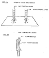
- the entire input device 11 is depicted in Fig. 2A.
- the input device 11 comprises a left control lever 11L operated with the player's left hand and a right control lever 11R operated with the right hand.
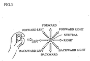
- Each control lever has a total of nine control attitudes, forward and back, left and right, diagonal, and neutral (see Fig. 3).
- Control signals which correspond to the various control attitudes are output as digital signal codes.
- the control levers are equipped with shot triggers 11S and turbo triggers 11T for acceleration; codes are output when these are depressed.
- Assignments should be made in such a way that the direction of motion of the actual object reflects as closely as possible the direction in which the player intuitively tries to move the movable object.
- these special actions should be assigned to prescribed control attitudes.
- control lever assignments In this embodiment, movement assignments are made in such a way that the movements intended by the player are reflected in the movements of the object, even for those actions which the player performs reflexively.
- the CPU 101 After one of the code combinations indicated in Fig. 4 has been input from the input device 11, the CPU 101, following the program assigned in the manner indicated in Fig. 4, generates the visual point coordinates and object coordinates for the next interval. Once these coordinates have been set, the CPU 101 makes collision determinations and overlap determinations for the physical objects.
- Objects, obstacles, and other physical objects are composed of a plurality of polygon data. For each physical object, a certain apex of a polygon which is an element of the physical object is selected as the origin, the entire shape is decided using a coordinate system which indicates the coordinates of the other apices (body coordinate system), and the data for polygons which make up the physical object is associated.
- body coordinate system body coordinate system
- a further requirement for image display is that physical objects in a virtual space be projected onto a two-dimensional plane which constitutes the field of vision in a manner similar to physical objects present in a virtual space observed from a given visual point (for example, camera photography).
- This is termed perspective projection
- the coordinate conversion performed through matrix operations for perspective projection is termed perspective conversion.
- It is the geometalyzer 110 that executes perspective conversion to produce the virtual image which is actually displayed.
- the geometalyzer 110 is connected to the shape data ROM 111 and the displaying device 112.
- the geometalyzer 110 is provided by the CPU 101 with data indicating the data required for perspective conversion as well as with the matrix data required for perspective conversion.
- the geometalyzer 110 performs perspective conversion on polygon data stored in the shape data ROM 111 to produce data converted from the three-dimensional coordinate system in virtual space to the field-of-vision coordinate system.
- polygon data for the explosion image is used.
- the displaying device 112 applies texture to the converted field-of-vision coordinate system shape data and outputs the result to the frame buffer 115. If, as a result of an overlap determination, the object or the like is to be hidden behind an obstacle, a prescribed show-through display (mesh treatment or translucent treatment) is performed. To apply textures, the displaying device 112 is connected to the texture data ROM 113 and the texture map RAM 114, and is also connected to the frame buffer 115.
- the scroll data processor 107 computes text and other scroll screen data (stored in ROM 102).
- the image synthesis device 116 imposes text data output from the processor 107 onto the image data provided by the aforementioned frame buffer 115 and re-synthesizes the image.
- the re-synthesized image data is output to the TV monitor 13 through the D/A converter 117.
- step S1 NO
- step S2 the CPU performs other processes
- step S1: YES the control signal is acquired.
- the control signal is ascertained for each interval after an interrupt request, and if the same input signal is input eight consecutive times, a determination of correct input is made.
- the counter is first set to the initial value n (step S3) and the left control lever control signal and right control lever control signal are input (step S4, S5).
- the CPU 101 compares the value of the control signal input during the previous interval with the currently input control signal value (step S6). If the two do not match (step S6: NO), a determination of unintended input is made, and the CPU awaits the next interrupt request (step 1). If the previous control signal value and the currently input control signal value are equal (step S6: YES), the CPU determines whether the same determination has been made eight times (step S7). If less than eight times (step S7: NO), the counter n is incremented (step S8) and the same procedure is repeated (steps S4 - S7). If the same value has been input eight times (step S7: YES), the system proceeds to generate a virtual image on the basis of the correct control signal.
- step S9 on the basis of the coordinates of the destination point of the player's robot (object), the CPU 101 creates a perspective conversion matrix, a matrix for perspective conversion of shape data in virtual space into the visual point coordinate system, and provides this to the geometalyzer 110.
- the CPU 101 provides the coprocessor 108 with the terrain data stored in ROM 109 and instructs the coprocessor to perform coordinate conversion for making a collision determination; if a "collision" result is produced, data indicating the necessary polygons is output to the geometalyzer 110.
- the CPU 101 instructs the geometalyzer 110 to produce show-through display.
- step S10 processing similar to that described in step S9 is performed for the enemy robot.
- the enemy robot can be made to move in accordance with the program stored in ROM 102, or made to move by another input device controlled by another player.
- step S11 the data required to designate polygons required for perspective conversion is provided to the geometalyzer 110.
- step S12 the geometalyzer 110 uses the provided perspective conversion matrix to perform perspective conversion for the designated shape data and supplies the result to the displaying device 112.
- the displaying device 112 performs texture application and the like for the perspective-converted polygons and outputs the result to the frame buffer 115.
- control levers output control signals which take the form of digital data, thereby minimizing the likelihood of unintended input. Since movable object movement assignments are made in such a way that objects can be moved correctly, control is facilitated, even in scenes where it is easy to make unintended moves. Special assignments are made for control attitudes which the player is thought unlikely to actually use, such as jumping, rotating, circling an enemy, rapid acceleration, and rapid stop, thereby allowing objects to be moved freely in three dimensions within a virtual space.
- the present invention is not limited to the embodiment described above and may be adapted in various ways.
- the input device was equipped with two control levers in the foregoing embodiment, but the present invention may be adapted to any configuration which outputs digital control signals, such as a joystick or control button that can be depressed in eight directions.
- the number of control directions is not limited to eight; implementation with more or fewer directions is possible.
- Control attitude assignments are not limited to the assignments indicated in Fig. 4 and permit of various modifications in accordance with the specifications of the game unit, simulator, or other unit equipped with the image generating device which pertains to the present invention.
- the virtual image generation method may employ various image generation methods pertaining to computer graphics.
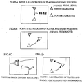
- Fig. 6 depicts example 1 (scene 1), illustrating moves to evade a bullet fired by a combat partner (enemy).
- a of the same figure depicts positional relationships at the instant the bullet is fired by the enemy; positions are viewed from above.
- the player manipulates the control levers in the manner shown in Fig. 4(1) to evade the bullet.
- the player's object performs a "slow circle counterclockwise to right".
- the player's object moves so as to circle the enemy.
- Scene 1 when actually displayed as a virtual image on a monitor, would appear as shown in C of the same figure. Since the visual point of the virtual image rotates with the movement of the player's object, the enemy's displayed position is virtually unchanged as the movement of the player's object to circle the enemy is displayed. This image display minimizes movement of the player's line of sight, reducing the demands placed on the player and allowing the excitement of real combat to be sustained.
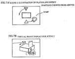
- Fig. 7 depicts example 2 (scene 2), illustrating an enemy and the player's object circling each other around an obstacle.
- a of the same figure shows the positional relationship of the enemy and the player's object. If only two dimensional movements within the virtual space can be specified, as with conventional game units, only movement around the same obstacle around which the two arc trying to circle is possible, thereby slowing the pace.
- the player's object can be made to "jump" as it circles, as shown in Fig. 4(4), thereby allowing the player's object to jump down on the enemy from above and attack the enemy, as shown in the actual virtual image in Fig. 7B.
- a "forward advance” control move after making the "jump” control move, the player's object can be moved toward the enemy while maintaining the same altitude. This affords a fast-paced game sequence without complicated control moves.
- a plurality of input device control attitudes are combined, and a specific movement is specified for each control attitude. This reduces the likelihood of unintended moves and facilitates control, thereby making it possible to freely control movable objects within virtual space.
- three-dimensional movement may be facilitated by assigning a jump move
- rotation of a movable object may be facilitated by assigning a rotating move
- motion on a circle around a prescribed axis may assigned to facilitate circling around an enemy.
Abstract
Description
- The present invention relates to a virtual image generation technique for use in game units, simulators, and the like, and particularly to a technique for generating images (hereinafter termed "virtual images") obtained when an object present in a virtual three-dimensional space (hereinafter termed "virtual space") is projected (by perspective projection) onto a two-dimensional plane which corresponds to a prescribed visual point.
- In recent years, game units and simulators equipped with on-board virtual image generation apparatuss which make it possible for movable objects (objects) which move through three-dimensional space to combat each other have been developed. Such virtual image generation apparatuss are usually equipped with a virtual image generation apparatus main unit that houses a computer unit for executing stored programs, an input device for sending control signals to the computer unit to instruct it to move objects displayed on the screen within the virtual image, a display for displaying the virtual images generated by the computer unit according to the program sequence, and a sound device for generating sounds according to the program sequence.
- Examples of devices with the architecture described above include driving game unit with a car race theme, in which cars compete with enemy cars on a circuit, and simulators which re-create the experience of piloting a helicopter or airplane. In this type of device, highly realistic simulation of car or helicopter movement is extremely important. For example, in a driving game like that depicted in Fig. 8A, input devices which resemble an actual car steering wheel, accelerator pedal, and brake pedal are used. In a helicopter or other simulator input device are processed by the CPU (central processing unit) of the computer unit. The computer unit repeatedly performs calculations to assign relative position within the virtual space to the objects, including data for enemy object motion when enemy objects are also present.
- As players become more skilled at playing games, it has become necessary to go beyond conventional motion and develop movable objects such as player-controlled robots, humans, and the like. Particularly in the field of game devices, games are being developed in which objects not only move in two dimensions over a terrain created in virtual space (hereinafter termed "virtual terrain"), but also jump up from a virtual terrain in order to jump over another character or engage in fights in midair.
- However, input devices for conventional virtual image generation apparatuss, while suitable for controlling two-dimensional motion of objects through a virtual space, are not adapted to controlling three-dimensional motion such as jumping. For example, in the driving games mentioned earlier, the steering wheel (which is the principal means of control) controls the movable object in the sideways direction (as viewed from the player's visual point), while the accelerator and brake pedals control motion in the forward direction; there is no way to control motion of the movable object in the vertical direction. Similarly, in simulators, a single control lever is used to control all motion of the movable object in three directions, the forward direction, sideways direction, and vertical direction.
- In combat-style game units, the game unit must afford control sufficient to permit agile motion in order to avoid an enemy attack. In such cases, a special control button or control lever to control jumping can be provided, but this makes operation complicated and does not allow the action to be transmitted to the game unit with the same sense of speed that the player desires. In addition, excessively feature-laden input devices entail higher costs.
- By way of improving control, a video game unit which affords simple game control using two control levers is taught in Japanese Laid-Open Patent Application 6-277363. In this example of the prior art, thrust vectors are assigned according to the control lever inclination of each of the two control levers, and the two vectors are synthesized to produce complex actions.
- However, in this example of the prior art, it is difficult to move the object rapidly in the desired direction through synthesis of the two vectors, and it is not possible to move the object freely to a desired position in three-dimensional space.
- In order to solve this problem, it is an object of the present invention to provide a virtual image generation method and device which allow a movable object to be moved freely and without input error in three dimensions within a virtual space, and to a device therefor.
- The invention of
Claim 1 is a virtual image generation method for generating virtual images which include movable objects (robots, airplanes, and the like) that undergo relative motion within a virtually created virtual space (a so-called world coordinate system), comprising the steps of generating codes associated with the operating direction of a plurality of (for example, two) input means (control levers, joysticks, or the like), assigning control profiles for movable objects associated with the code combinations generated by the plurality of input means, and generating virtual images wherein the assigned control profiles are reflected in relative motion of the movable objects within virtual space. - The invention of
Claim 2 is a virtual image generation apparatus for generating virtual images which include movable objects that undergo relative motion within a virtually created virtual space, comprising a plurality of (for example, two) input means (control levers, joy sticks, or the like) for generating codes associated with operating direction, decoding means (a CPU, controller, or the like) for inputting the codes generated through operation of the plurality of input means, and assigning a control profile for a movable object associated with a combination of a plurality of input codes, and image generation means (a CPU, geometalyzer, graphic controller, or the like) for generating virtual images whereby the movable object control profiles assigned by the decoding means arc reflected in relative motion of the movable objects within virtual space. - As the aforementioned control profile, the invention of
Claim 3 is a virtual image generation apparatus as defined inClaim 2, wherein the decoding means, in the event that a combination of codes input from the input means matches a prescribed combination (for example, when the left input means is tilted to the left and the right input means is tilted to the right), assumes that the direction corresponding to the perpendicular direction with respect to a horizontal plane in the virtual space through which the movable object moves is the upward direction, whereupon the decoding means assigns a control profile such that the movable object moves upward, and the image generation means, in the event that the assigned control profile is such that the movable object is moved upward, generates a virtual image whereby the movable object moves upward from a horizontal plane in the virtual space. - As an alternative control profile, the invention of
Claim 4 is a virtual image generation apparatus as defined inClaim 2, wherein the decoding means, in the event that a combination of codes input from the input means matches a prescribed combination (for example, when the left input means is moved forward and the right input means is lowered towards the player), assigns a control profile such that the movable object rotates while remaining in the same position within the virtual space, and the image generation means, in the event that the assigned control profile is such that the movable object is rotated, generates a virtual image whereby the movable object rotates while remaining in the same position within the virtual space. - As an alternative control profile, the invention of Claim 5 is a virtual image generation apparatus as defined in
Claim 2, wherein the decoding means, in the event that a combination of codes input from the input means matches a prescribed combination (for example, when the left input means is moved forward diagonally towards the right and the right input means is lowered towards the right), assigns a control profile such that the movable object moves in the lateral direction along a prescribed circle which is centered upon a prescribed central axis within the virtual space, and the image generation means, in the event that the assigned control profile is such that the movable object is moved in the lateral direction along said circle, generates a virtual image whereby the movable object moves in the lateral direction along said circle. - The invention of Claim 6 is a virtual image generation apparatus as defined in
Claim 2, wherein the input means are control levers which generate a center position code when moved to a prescribed location and which generate a different code when moved in any of eight directions from the prescribed location. - Switch or control buttons that can detect a neutral position and eight directions may be substituted for the control levers.
- In accordance with the invention of
Claim 1 orClaim 2, numerous code combinations are afforded by the control attitudes of the plurality of control means. By associating these various combinations with various motions of movable objects in virtual space, the movable objects can be induced to undergo complex motion. Therefore, the movement of a movable object can be clearly defined through selection of a given control attitude, and by perspective projection of the movable object, the virtual terrain, and the like with reference to this defined movement, virtual images adapted to game units, simulators, and the like can be generated. - Even under conditions where there is a high likelihood of unintended operation, such as when the player operates the input device in an intuitive fashion in order to dodge a bullet, assigning movable object movements in such a way that such movements approximate those movements which are presumably intended by the player reduces the likelihood of unintended operation, thereby reducing the demands placed upon the player. By assigning three dimensional movements, such as jumping by a movable object, in addition to two-dimensional movements, it becomes possible to move the movable object in three dimensions.
- Specifically, in accordance with the invention of
Claim 3, movement in a direction corresponding to the perpendicular direction from a horizontal plane in a virtual space is assigned to a specific operation, thereby allowing the three-dimensional movement of a movable object to be controlled by means of a prescribed operation. - In accordance with the invention of
Claim 4, rotation in a fixed position is assigned to a specific operation, thereby allowing the orientation of the movable object to be changed without changing its two dimensional position in a virtual space by means of a prescribed operation. - In accordance with the invention of Claim 5, orbit around a prescribed central axis is assigned to a specific operation, making possible actions such as orbiting around an enemy character by means of a prescribed operation.
- In accordance with the invention of Claim 6, control levers are employed as the control means, and each control lever can maintain nine different control attitudes. Thus, the use of a plurality of control levers affords a number of combinations sufficient to allow control of complex movements by a movable object.
-
- Fig. 1 is a simplified block diagram of a game unit pertaining to an embodiment of the present invention;
- Fig. 2 is an illustrative diagram of input devices (control levers) pertaining to the embodiment;
- Fig. 3 is an illustrative diagram of the control lever operation method;
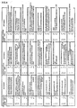
- Fig. 4 is an assignment diagram showing the control attitudes of the left and right control levers and the associated movements of a movable object in the embodiment;
- Fig. 5 is a flow chart illustrating the operation of the game unit pertaining to the embodiment;
- Fig. 6 is a diagram which illustrates
embodiment 1; - Fig. 7 is a diagram which illustrates
embodiment 2; and - Fig. 8 is a diagram depicting an input device for a conventional virtual image generation apparatus.
- Favorable embodiments of the present invention will be described below with reference to the drawings.
- A structural diagram of a game unit which represents one embodiment of the present invention is presented in Fig. 1. In this embodiment, a robot serves as the movable object. Controlled by the player, the robot moves freely within the virtual space, engaging in combat with enemy robots.
- As shown in Fig. 1, the
game unit 1000 comprises the following basic structural elements: a game unitmain body 10, an input device 11, anoutput device 12, aTV monitor 13, and aspeaker 14. - The input device 11 is provided with control levers which are operated with the player's left and right hands in order to control the movement of the robot. The
output device 12 is provided with various types of lamps which notify the player of the operational status of the unit. TheTV monitor 13 displays the combat game image; a head mounted display (HMD), projector, or the like may be used in place of a TV monitor. - As image generation means, the game unit
main body 10 has acounter 100 and a CPU (central processing unit) 101; it is also equipped withROM 102,RAM 103, asound device 104, an I/O interface 106, ascroll data processor 107, acoprocessor 108,terrain data ROM 109, a geometalyzer 110,shape data ROM 111, a displayingdevice 112,texture data ROM 113,texture map RAM 114, aframe buffer 115, animage synthesis device 116, and a D/A converter 117. The game unitmain body 10 generates new virtual images at prescribed intervals (for example, each 1/60th of a second, corresponding to the vertical sync cycle of the television format). - The
CPU 101, which serves as the decoding means, is connected via buslines to thecounter 100, which stores initial values, to theROM 102, which stores the program for the game sequence and image generation, to theRAM 103, which stores temporary data, and to thesound card 104, I/O interface 106, scrolldata processor 107,coprocessor 108, and geometalyzer 110. - The
RAM 103 temporarily stores data required for polygon data coordinate conversion and other functions, and stores various commands for the geometalyzer (such as object display commands), the results of matrix operations during conversion process operations, and other data. - When the player enters control signals through the input device 11, the I/
O interface 106 issues interrupt requests to theCPU 101; when theCPU 101 sends data for lamp display, this data is sent to theoutput device 12. - The
sound card 104 is connected to aspeaker 14 through apower amplifier 105. Audio signals output by thesound card 104 are amplified by thepower amplifier 105 and delivered to thespeaker 14. - The
ROM 111 stores the polygon data required to generate virtual images of various physical objects such as the player's robot, enemy robots, bomb explosion images, and elements of the virtual terrain such as obstacles, background, and topographical features. - The
ROM 109 stores shape data for physical objects (buildings, obstacles, topographical features, and the like) concerning which it is necessary to make overlap decisions, i.e., whether an object should collide with another topographical feature, or be hidden by a topographical feature. In contrast to the relatively detailed polygon data groupings for image display stored in theROM 111, the data groupings stored in theROM 109 comprise rough units sufficient to perform overlap decisions and the like. For example, topographical feature data might include an ID for each surface which defines a topographical feature, and what is termed relationship of this ID and topographical feature surface is put in table form and stored in theROM 111. - What is termed polygon data are data groupings which are sets comprising a plurality of apices, and which indicate the apices of polygons (usually triangles or quadrangles), the elements that make up the shape of a physical object, as relative coordinates or absolute coordinates.
- In order to generate virtual images, a coordinate system (world coordinate system) which indicates the relative positions of objects, obstacles, and other physical objects in a virtual space, must be converted to a two-dimensional coordinate system (visual point coordinate system) which represents the virtual space viewed from a designated visual point (for example, a camera or the like). The visual point is set at some prescribed position (for example, diagonally above the object) from which the object to be controlled is visible. Thus, the visual point coordinates change in accordance with the object coordinates. The object coordinates are sent as control signals from the input device 11 to the
CPU 101. - The entire input device 11 is depicted in Fig. 2A. As may be discerned from the drawing, the input device 11 comprises a
left control lever 11L operated with the player's left hand and aright control lever 11R operated with the right hand. Each control lever has a total of nine control attitudes, forward and back, left and right, diagonal, and neutral (see Fig. 3). Control signals which correspond to the various control attitudes are output as digital signal codes. As shown in Fig. 2B, the control levers are equipped with shot triggers 11S and turbo triggers 11T for acceleration; codes are output when these are depressed. - Fig. 4 shows the object movement assignments for the control attitudes. Since each control lever has nine codes, simultaneous operation of both the left and right control levers gives a total of 81 possible combinations (= 9 possibilities × 9 possibilities). If a direction of motion of an object which is to be moved at the next interval is assigned to each combination, a total of 81 actions can be specified using two control levers.
- Assignments should be made in such a way that the direction of motion of the actual object reflects as closely as possible the direction in which the player intuitively tries to move the movable object. However, since horizontal movement on the true horizontal, movement in a diagonal direction, and rotating, as well as jumping in the perpendicular direction from a horizontal plane in virtual space (the z-direction in the world coordinate system) are performed, these special actions should be assigned to prescribed control attitudes.
- When the player is attacked by enemies, he or she moves the control levers to instinctively dodge enemy bullets in order to avoid the attack. With the control lever assignments in this embodiment, movement assignments are made in such a way that the movements intended by the player are reflected in the movements of the object, even for those actions which the player performs reflexively.
- Once one of the code combinations indicated in Fig. 4 has been input from the input device 11, the
CPU 101, following the program assigned in the manner indicated in Fig. 4, generates the visual point coordinates and object coordinates for the next interval. Once these coordinates have been set, theCPU 101 makes collision determinations and overlap determinations for the physical objects. - Objects, obstacles, and other physical objects are composed of a plurality of polygon data. For each physical object, a certain apex of a polygon which is an element of the physical object is selected as the origin, the entire shape is decided using a coordinate system which indicates the coordinates of the other apices (body coordinate system), and the data for polygons which make up the physical object is associated. In order to enable display of an explosion image when an object or obstacle is hit by a bullet or light ray, it is necessary to compute the relative positions of the physical objects and determine whether the physical objects have collided. To obtain relative position for a physical object represented by body coordinates, conversion to the prescribed coordinate system which makes up the virtual space (world coordinate system) must be made. Once the relative position for each physical object has been determined, it becomes possible to determine whether the physical objects collide with each other.
- In order to enable show-through display of an obstacle when, from the visual point from which a virtual space is observed, an object or the like passes behind the obstacle, it is necessary to perform a determination of overlap status for the physical objects. To do this, the physical objects in the virtual space are converted to the coordinate system for viewing from the visual point, and a relative vector for the obstacle and object and a line-of-sight vector for the object and visual point are calculated. Once the angles of the two vectors have been computed, it can be determined whether the object should be hidden by obstacle or not. Since these computations entail coordinate conversion, matrix operations which include floating decimal point operations are required. Matrix operations are performed by the
coprocessor 108 making reference to terrain data and the like stored inROM 109; as a result of the operations, theCPU 101 makes a collision determination or overlap determination. - A further requirement for image display is that physical objects in a virtual space be projected onto a two-dimensional plane which constitutes the field of vision in a manner similar to physical objects present in a virtual space observed from a given visual point (for example, camera photography). This is termed perspective projection, and the coordinate conversion performed through matrix operations for perspective projection is termed perspective conversion. It is the geometalyzer 110 that executes perspective conversion to produce the virtual image which is actually displayed.
- The geometalyzer 110 is connected to the
shape data ROM 111 and the displayingdevice 112. The geometalyzer 110 is provided by theCPU 101 with data indicating the data required for perspective conversion as well as with the matrix data required for perspective conversion. On the basis of the matrix provided by theCPU 101, the geometalyzer 110 performs perspective conversion on polygon data stored in theshape data ROM 111 to produce data converted from the three-dimensional coordinate system in virtual space to the field-of-vision coordinate system. At this time, if it is necessary to display an explosion image as a result of a collision determination by theCPU 101, polygon data for the explosion image is used. - The displaying
device 112 applies texture to the converted field-of-vision coordinate system shape data and outputs the result to theframe buffer 115. If, as a result of an overlap determination, the object or the like is to be hidden behind an obstacle, a prescribed show-through display (mesh treatment or translucent treatment) is performed. To apply textures, the displayingdevice 112 is connected to thetexture data ROM 113 and thetexture map RAM 114, and is also connected to theframe buffer 115. - The
scroll data processor 107 computes text and other scroll screen data (stored in ROM 102). Theimage synthesis device 116 imposes text data output from theprocessor 107 onto the image data provided by theaforementioned frame buffer 115 and re-synthesizes the image. The re-synthesized image data is output to theTV monitor 13 through the D/A converter 117. - Next, the operation in this embodiment will be described referring to the flow chart in Fig. 5.
- When the player moves the
left control lever 11L, the right control lever, or both, thereby inputting a new control signal to the I/O interface 106, the I/O interface 106 makes an interrupt request to theCPU 101. If there is no interrupt (step S1: NO), the CPU performs other processes (step S2), but if an interrupt request has been made, (step S1: YES), the control signal is acquired. - In this embodiment, in order to determine a way of doing unintended input or not, the control signal is ascertained for each interval after an interrupt request, and if the same input signal is input eight consecutive times, a determination of correct input is made. To do this, the counter is first set to the initial value n (step S3) and the left control lever control signal and right control lever control signal are input (step S4, S5).
- The
CPU 101 compares the value of the control signal input during the previous interval with the currently input control signal value (step S6). If the two do not match (step S6: NO), a determination of unintended input is made, and the CPU awaits the next interrupt request (step 1). If the previous control signal value and the currently input control signal value are equal (step S6: YES), the CPU determines whether the same determination has been made eight times (step S7). If less than eight times (step S7: NO), the counter n is incremented (step S8) and the same procedure is repeated (steps S4 - S7). If the same value has been input eight times (step S7: YES), the system proceeds to generate a virtual image on the basis of the correct control signal. - In step S9, on the basis of the coordinates of the destination point of the player's robot (object), the
CPU 101 creates a perspective conversion matrix, a matrix for perspective conversion of shape data in virtual space into the visual point coordinate system, and provides this to the geometalyzer 110. At the same time, theCPU 101 provides thecoprocessor 108 with the terrain data stored inROM 109 and instructs the coprocessor to perform coordinate conversion for making a collision determination; if a "collision" result is produced, data indicating the necessary polygons is output to the geometalyzer 110. Where vector operations for making an overlap determination have produced an overlap result, theCPU 101 instructs the geometalyzer 110 to produce show-through display. - In step S10, processing similar to that described in step S9 is performed for the enemy robot. The enemy robot can be made to move in accordance with the program stored in
ROM 102, or made to move by another input device controlled by another player. - In step S11, the data required to designate polygons required for perspective conversion is provided to the geometalyzer 110.
- In step S12, the geometalyzer 110 uses the provided perspective conversion matrix to perform perspective conversion for the designated shape data and supplies the result to the displaying
device 112. The displayingdevice 112 performs texture application and the like for the perspective-converted polygons and outputs the result to theframe buffer 115. - With the embodiment described above, the control levers output control signals which take the form of digital data, thereby minimizing the likelihood of unintended input. Since movable object movement assignments are made in such a way that objects can be moved correctly, control is facilitated, even in scenes where it is easy to make unintended moves. Special assignments are made for control attitudes which the player is thought unlikely to actually use, such as jumping, rotating, circling an enemy, rapid acceleration, and rapid stop, thereby allowing objects to be moved freely in three dimensions within a virtual space.
- The present invention is not limited to the embodiment described above and may be adapted in various ways.
- For example, the input device was equipped with two control levers in the foregoing embodiment, but the present invention may be adapted to any configuration which outputs digital control signals, such as a joystick or control button that can be depressed in eight directions. The number of control directions is not limited to eight; implementation with more or fewer directions is possible.
- Control attitude assignments are not limited to the assignments indicated in Fig. 4 and permit of various modifications in accordance with the specifications of the game unit, simulator, or other unit equipped with the image generating device which pertains to the present invention.
- As the present invention was designed with the principal aim of facilitating control of movable objects in virtual space, the virtual image generation method may employ various image generation methods pertaining to computer graphics.
- An example in which the
game unit 1000 in the aforementioned embodiment of the invention is actually used will be described. - Fig. 6 depicts example 1 (scene 1), illustrating moves to evade a bullet fired by a combat partner (enemy).
- A of the same figure depicts positional relationships at the instant the bullet is fired by the enemy; positions are viewed from above. As in the previous embodiment, the player manipulates the control levers in the manner shown in Fig. 4(1) to evade the bullet. If control lever assignments have been made in the manner indicated in Fig. 4, the player's object performs a "slow circle counterclockwise to right". As shown in Fig. 6B, the player's object moves so as to circle the enemy.
Scene 1, when actually displayed as a virtual image on a monitor, would appear as shown in C of the same figure. Since the visual point of the virtual image rotates with the movement of the player's object, the enemy's displayed position is virtually unchanged as the movement of the player's object to circle the enemy is displayed. This image display minimizes movement of the player's line of sight, reducing the demands placed on the player and allowing the excitement of real combat to be sustained. - As shown in D of the same figure, to advance the player's object forward after circling the enemy in order to counterattack, the player should lower both control levers in the forward direction (Fig. 4(2)). To perform both rapid circling and forward advance within a short time, the player can on occasion lower the control levers in the manner depicted in Fig. 4(3).
- However, with the assignments indicated in Fig. 4, such frequently used control attitudes are reflected in the object as movements intended by the player, so the player's object can be advanced toward the enemy. That is, when objects are controlled through a synthesis vector for two levers, as described in the Background Art, the operation indicated in Fig. 4(3) can easily give rise to an unintended move; in this example, however, the operation indicated in Fig. 4(3) has the assignment "advance diagonally slightly to left", thereby allowing the object to be moved in the intended direction without slowing the pace of the game sequence.
- Fig. 7 depicts example 2 (scene 2), illustrating an enemy and the player's object circling each other around an obstacle.
- A of the same figure shows the positional relationship of the enemy and the player's object. If only two dimensional movements within the virtual space can be specified, as with conventional game units, only movement around the same obstacle around which the two arc trying to circle is possible, thereby slowing the pace.
- With this example, the player's object can be made to "jump" as it circles, as shown in Fig. 4(4), thereby allowing the player's object to jump down on the enemy from above and attack the enemy, as shown in the actual virtual image in Fig. 7B. By making a "forward advance" control move after making the "jump" control move, the player's object can be moved toward the enemy while maintaining the same altitude. This affords a fast-paced game sequence without complicated control moves.
- In accordance with the present invention, a plurality of input device control attitudes are combined, and a specific movement is specified for each control attitude. This reduces the likelihood of unintended moves and facilitates control, thereby making it possible to freely control movable objects within virtual space.
- For selected control attitudes, three-dimensional movement may be facilitated by assigning a jump move, rotation of a movable object may be facilitated by assigning a rotating move, and motion on a circle around a prescribed axis may assigned to facilitate circling around an enemy.
Claims (6)
- A virtual image generation method for generating virtual images which include movable objects that undergo relative motion within a virtually created virtual space, comprising the steps of:generating codes associated with the operating direction of a plurality of input means, assigning control profiles for said movable objects associated with the code combinations generated by said plurality of input means, and generating said virtual images wherein said assigned control profiles are reflected in the relative motion of said movable objects within said virtual space.
- A virtual image generation apparatus for generating virtual images which include movable objects that undergo relative motion within a virtually created virtual space, comprising:a plurality of input means for generating codes associated with operating direction;decoding means for inputting the codes generated through operation of said plurality of input means, and assigning a control profile for said movable object associated with a combination of a plurality of input codes; andimage generation means for generating said virtual images wherein said movable object control profiles assigned by said decoding means are reflected in the relative motion of said movable objects within said virtual space.
- A virtual image generation apparatus as defined in Claim 2, wherein said decoding means, in the event that a combination of codes input from said input means matches a prescribed combination, assumes that the direction corresponding to the perpendicular direction with respect to a horizontal plane in said virtual space through which said movable object moves is the upward direction, whereupon it assigns a control profile such that said movable object moves in said upward direction; and
said image generation means, in the event that said assigned control profile is such that said movable object is moved in the vertical direction, generates a virtual image whereby said movable object moves in said vertical direction from a horizontal plane in said virtual space. - A virtual image generation apparatus as defined in Claim 2, wherein said decoding means, in the event that a combination of codes input from said input means matches a prescribed combination, assigns a control profile such that said movable object is rotated while remaining in the same position within said virtual space, and
said image generation means, in the event that said assigned control profile is such that the movable object rotates, generates a virtual image whereby said movable object rotates while remaining in the same position within said virtual space. - A virtual image generation apparatus as defined in Claim 2, wherein said decoding means, in the event that a combination of codes input from said input means matches a prescribed combination, assigns a control profile such that said movable object moves in the lateral direction along a prescribed circle which is centered upon a prescribed central axis within said virtual space, and
said image generation means, in the event that said assigned control profile is such that said movable object is moved in the lateral direction along said circle, generates a virtual image whereby said movable object moves in the lateral direction along said circle. - A virtual image generation apparatus as defined in Claim 2, wherein said input means are control levers which generate a center position code when moved to a prescribed location and which generate a different code when moved in any of eight directions located around said prescribed location.
Applications Claiming Priority (3)
| Application Number | Priority Date | Filing Date | Title |
|---|---|---|---|
| JP20484895A JP3734045B2 (en) | 1995-08-10 | 1995-08-10 | Virtual image generation method and apparatus |
| JP204848/95 | 1995-08-10 | ||
| PCT/JP1996/002267 WO1997006510A1 (en) | 1995-08-10 | 1996-08-09 | Virtual image formation method and its apparatus |
Publications (3)
| Publication Number | Publication Date |
|---|---|
| EP0802508A1 true EP0802508A1 (en) | 1997-10-22 |
| EP0802508A4 EP0802508A4 (en) | 1998-12-16 |
| EP0802508B1 EP0802508B1 (en) | 2006-01-04 |
Family
ID=16497402
Family Applications (1)
| Application Number | Title | Priority Date | Filing Date |
|---|---|---|---|
| EP96926619A Expired - Lifetime EP0802508B1 (en) | 1995-08-10 | 1996-08-09 | Input device for image formation method and its apparatus |
Country Status (10)
| Country | Link |
|---|---|
| US (1) | US6154197A (en) |
| EP (1) | EP0802508B1 (en) |
| JP (1) | JP3734045B2 (en) |
| KR (1) | KR100455689B1 (en) |
| CN (1) | CN1136519C (en) |
| BR (1) | BR9606579A (en) |
| CA (1) | CA2201754A1 (en) |
| DE (1) | DE69635710T2 (en) |
| ES (1) | ES2257751T3 (en) |
| WO (1) | WO1997006510A1 (en) |
Cited By (2)
| Publication number | Priority date | Publication date | Assignee | Title |
|---|---|---|---|---|
| EP1300181A3 (en) * | 2001-10-02 | 2004-12-15 | Konami Corporation | Game device, game control method and program |
| EP1887452A1 (en) * | 2006-08-09 | 2008-02-13 | STMicroelectronics (Research & Development) Limited | Human-Computer Interface |
Families Citing this family (31)
| Publication number | Priority date | Publication date | Assignee | Title |
|---|---|---|---|---|
| DE69625523T2 (en) | 1995-05-10 | 2003-07-10 | Nintendo Co Ltd | Control unit with analog joystick |
| JP3141737B2 (en) * | 1995-08-10 | 2001-03-05 | 株式会社セガ | Virtual image generation apparatus and method |
| CN1149465C (en) | 1995-10-09 | 2004-05-12 | 任天堂株式会社 | Stereo image processing system |
| JP3544268B2 (en) | 1995-10-09 | 2004-07-21 | 任天堂株式会社 | Three-dimensional image processing apparatus and image processing method using the same |
| JP3524247B2 (en) | 1995-10-09 | 2004-05-10 | 任天堂株式会社 | Game machine and game machine system using the same |
| US6022274A (en) | 1995-11-22 | 2000-02-08 | Nintendo Co., Ltd. | Video game system using memory module |
| US6155926A (en) | 1995-11-22 | 2000-12-05 | Nintendo Co., Ltd. | Video game system and method with enhanced three-dimensional character and background control |
| US6139434A (en) | 1996-09-24 | 2000-10-31 | Nintendo Co., Ltd. | Three-dimensional image processing apparatus with enhanced automatic and user point of view control |
| JP3844396B2 (en) * | 1998-04-24 | 2006-11-08 | 株式会社バンダイナムコゲームス | GAME DEVICE AND INFORMATION STORAGE MEDIUM |
| JP3646969B2 (en) * | 1998-05-25 | 2005-05-11 | 富士通株式会社 | 3D image display device |
| JPH11342265A (en) * | 1998-06-01 | 1999-12-14 | Sony Computer Entertainment Inc | Record medium and entertainment system |
| JP4278071B2 (en) | 1999-06-17 | 2009-06-10 | 株式会社バンダイナムコゲームス | Image generation system and information storage medium |
| JP2001079264A (en) * | 1999-09-14 | 2001-03-27 | Atlus Co Ltd | Game device |
| JP3321570B2 (en) * | 1999-09-14 | 2002-09-03 | 株式会社ソニー・コンピュータエンタテインメント | Moving image creation method, storage medium, and program execution device |
| JP4507320B2 (en) * | 1999-12-17 | 2010-07-21 | 株式会社セガ | game machine |
| JP4741164B2 (en) * | 2000-07-17 | 2011-08-03 | 株式会社ソニー・コンピュータエンタテインメント | Program execution system, program execution device, recording medium, and image display method |
| EP1174167B1 (en) | 2000-07-17 | 2006-12-27 | Sony Computer Entertainment Inc. | Program execution system, program execution device and recording medium and computer executable program therefor |
| US7038660B2 (en) * | 2003-03-13 | 2006-05-02 | Sony Corporation | Wheel motion control input device for animation system |
| JP2006051586A (en) * | 2004-08-13 | 2006-02-23 | Speecys Kk | Robot control system |
| US20060250351A1 (en) * | 2004-09-21 | 2006-11-09 | Fu Peng C | Gamepad controller mapping |
| JP4388878B2 (en) * | 2004-10-19 | 2009-12-24 | 任天堂株式会社 | Input processing program and input processing apparatus |
| JP2006280731A (en) * | 2005-04-01 | 2006-10-19 | Aruze Corp | Game program, game apparatus and recording medium |
| JP4262217B2 (en) * | 2005-04-26 | 2009-05-13 | 任天堂株式会社 | GAME PROGRAM AND GAME DEVICE |
| JP2006305176A (en) * | 2005-04-28 | 2006-11-09 | Nintendo Co Ltd | Game program and game device |
| JP4260770B2 (en) * | 2005-05-09 | 2009-04-30 | 任天堂株式会社 | GAME PROGRAM AND GAME DEVICE |
| JP5230901B2 (en) * | 2005-11-14 | 2013-07-10 | 株式会社ハル研究所 | GAME PROGRAM, GAME DEVICE, GAME CONTROL METHOD, AND GAME SYSTEM |
| JP5305561B2 (en) * | 2006-02-22 | 2013-10-02 | 任天堂株式会社 | GAME PROGRAM AND GAME DEVICE |
| JP5294442B2 (en) * | 2006-09-13 | 2013-09-18 | 任天堂株式会社 | GAME DEVICE AND GAME PROGRAM |
| JP5339490B2 (en) * | 2012-08-21 | 2013-11-13 | 任天堂株式会社 | GAME DEVICE AND GAME PROGRAM |
| WO2018020853A1 (en) * | 2016-07-29 | 2018-02-01 | Necソリューションイノベータ株式会社 | Mobile body control system, control signal transmission system, mobile body control method, program, and recording medium |
| JP6744033B2 (en) | 2016-07-29 | 2020-08-19 | Necソリューションイノベータ株式会社 | Mobile control system, control signal transmission system, mobile control method, program, and recording medium |
Citations (1)
| Publication number | Priority date | Publication date | Assignee | Title |
|---|---|---|---|---|
| WO1994024685A1 (en) * | 1993-04-09 | 1994-10-27 | Kinesis Corporation | Ergonomic keyboard and pointing apparatus and method |
Family Cites Families (3)
| Publication number | Priority date | Publication date | Assignee | Title |
|---|---|---|---|---|
| US5317505A (en) * | 1990-12-19 | 1994-05-31 | Raznik Karabed | Game controller capable of storing and executing stored sequences of user playing button settings |
| US5259626A (en) * | 1992-08-07 | 1993-11-09 | Std Electronic International Ltd. | Programmable video game controller |
| JP2799126B2 (en) * | 1993-03-26 | 1998-09-17 | 株式会社ナムコ | Video game device and game input device |
-
1995
- 1995-08-10 JP JP20484895A patent/JP3734045B2/en not_active Expired - Fee Related
-
1996
- 1996-08-09 WO PCT/JP1996/002267 patent/WO1997006510A1/en active IP Right Grant
- 1996-08-09 CA CA002201754A patent/CA2201754A1/en not_active Abandoned
- 1996-08-09 EP EP96926619A patent/EP0802508B1/en not_active Expired - Lifetime
- 1996-08-09 US US08/817,243 patent/US6154197A/en not_active Expired - Lifetime
- 1996-08-09 BR BR9606579A patent/BR9606579A/en unknown
- 1996-08-09 KR KR1019970702316A patent/KR100455689B1/en not_active IP Right Cessation
- 1996-08-09 DE DE69635710T patent/DE69635710T2/en not_active Expired - Lifetime
- 1996-08-09 ES ES96926619T patent/ES2257751T3/en not_active Expired - Lifetime
- 1996-08-09 CN CNB961908874A patent/CN1136519C/en not_active Expired - Fee Related
Patent Citations (1)
| Publication number | Priority date | Publication date | Assignee | Title |
|---|---|---|---|---|
| WO1994024685A1 (en) * | 1993-04-09 | 1994-10-27 | Kinesis Corporation | Ergonomic keyboard and pointing apparatus and method |
Non-Patent Citations (1)
| Title |
|---|
| See also references of WO9706510A1 * |
Cited By (2)
| Publication number | Priority date | Publication date | Assignee | Title |
|---|---|---|---|---|
| EP1300181A3 (en) * | 2001-10-02 | 2004-12-15 | Konami Corporation | Game device, game control method and program |
| EP1887452A1 (en) * | 2006-08-09 | 2008-02-13 | STMicroelectronics (Research & Development) Limited | Human-Computer Interface |
Also Published As
| Publication number | Publication date |
|---|---|
| MX9702604A (en) | 1998-05-31 |
| DE69635710D1 (en) | 2006-03-30 |
| ES2257751T3 (en) | 2006-08-01 |
| KR970706553A (en) | 1997-11-03 |
| CA2201754A1 (en) | 1997-02-20 |
| EP0802508A4 (en) | 1998-12-16 |
| BR9606579A (en) | 1997-09-30 |
| CN1136519C (en) | 2004-01-28 |
| EP0802508B1 (en) | 2006-01-04 |
| US6154197A (en) | 2000-11-28 |
| CN1161095A (en) | 1997-10-01 |
| JP3734045B2 (en) | 2006-01-11 |
| JPH0950539A (en) | 1997-02-18 |
| DE69635710T2 (en) | 2006-08-10 |
| KR100455689B1 (en) | 2005-04-06 |
| WO1997006510A1 (en) | 1997-02-20 |
Similar Documents
| Publication | Publication Date | Title |
|---|---|---|
| EP0802508B1 (en) | Input device for image formation method and its apparatus | |
| US6261179B1 (en) | Video game system and video game memory medium | |
| US6296570B1 (en) | Video game system and video game memory medium | |
| US20020198047A1 (en) | Game device | |
| EP0778548B1 (en) | Image processor and game machine using the same | |
| US6377277B1 (en) | Virtual image generation apparatus and method | |
| US5616031A (en) | System and method of shadowing an object in motion | |
| EP1047022B1 (en) | Image generating device | |
| US6196919B1 (en) | Shooting game apparatus, method of performing shooting game, and computer-readable recording medium storing shooting game program | |
| WO1994022544A1 (en) | Video game machine | |
| JP2010273987A (en) | Program, information storage medium and image forming system | |
| JPH09223246A (en) | Game picture displaying method and game system | |
| JPH08229238A (en) | Three-dimensional shooting game machine | |
| JP3447397B2 (en) | 3D simulator apparatus and image composition method | |
| JP3642779B2 (en) | 3D simulator apparatus and image composition method | |
| JP2011255114A (en) | Program, information storage medium, and image generation system | |
| JP3686078B2 (en) | GAME DEVICE AND GAME IMAGE SYNTHESIS METHOD | |
| MXPA97002604A (en) | Method for the generation of virtual image and suapar | |
| JP3990050B2 (en) | GAME DEVICE AND INFORMATION STORAGE MEDIUM | |
| JP3836121B2 (en) | Home game device and game image composition method for home game device | |
| JP2000040169A (en) | Image processor and game device using the same | |
| JP3771248B2 (en) | Home game device and game image composition method for home game device |
Legal Events
| Date | Code | Title | Description |
|---|---|---|---|
| PUAI | Public reference made under article 153(3) epc to a published international application that has entered the european phase |
Free format text: ORIGINAL CODE: 0009012 |
|
| 17P | Request for examination filed |
Effective date: 19970409 |
|
| AK | Designated contracting states |
Kind code of ref document: A1 Designated state(s): AT BE CH DE DK ES FI FR GB GR IE IT LI LU MC NL PT SE Kind code of ref document: A1 Designated state(s): DE ES FR GB IT |
|
| A4 | Supplementary search report drawn up and despatched |
Effective date: 19981102 |
|
| AK | Designated contracting states |
Kind code of ref document: A4 Designated state(s): AT BE CH DE DK ES FI FR GB GR IE IT LI LU MC NL PT SE |
|
| RBV | Designated contracting states (corrected) |
Designated state(s): DE ES FR GB IT |
|
| 17Q | First examination report despatched |
Effective date: 20030520 |
|
| GRAP | Despatch of communication of intention to grant a patent |
Free format text: ORIGINAL CODE: EPIDOSNIGR1 |
|
| RIC1 | Information provided on ipc code assigned before grant |
Ipc: 7G 06F 3/033 B Ipc: 7A 63F 13/00 A |
|
| RTI1 | Title (correction) |
Free format text: INPUT DEVICE FOR IMAGE FORMATION METHOD AND ITS APPARATUS |
|
| RIC1 | Information provided on ipc code assigned before grant |
Ipc: 7G 06F 3/033 B Ipc: 7A 63F 13/00 A |
|
| GRAS | Grant fee paid |
Free format text: ORIGINAL CODE: EPIDOSNIGR3 |
|
| GRAA | (expected) grant |
Free format text: ORIGINAL CODE: 0009210 |
|
| AK | Designated contracting states |
Kind code of ref document: B1 Designated state(s): DE ES FR GB IT |
|
| REG | Reference to a national code |
Ref country code: GB Ref legal event code: FG4D |
|
| REF | Corresponds to: |
Ref document number: 69635710 Country of ref document: DE Date of ref document: 20060330 Kind code of ref document: P |
|
| RAP2 | Party data changed (patent owner data changed or rights of a patent transferred) |
Owner name: SEGA CORPORATION |
|
| REG | Reference to a national code |
Ref country code: ES Ref legal event code: FG2A Ref document number: 2257751 Country of ref document: ES Kind code of ref document: T3 |
|
| ET | Fr: translation filed | ||
| PLBE | No opposition filed within time limit |
Free format text: ORIGINAL CODE: 0009261 |
|
| STAA | Information on the status of an ep patent application or granted ep patent |
Free format text: STATUS: NO OPPOSITION FILED WITHIN TIME LIMIT |
|
| 26N | No opposition filed |
Effective date: 20061005 |
|
| REG | Reference to a national code |
Ref country code: FR Ref legal event code: CD |
|
| PGFP | Annual fee paid to national office [announced via postgrant information from national office to epo] |
Ref country code: ES Payment date: 20110825 Year of fee payment: 16 |
|
| PGFP | Annual fee paid to national office [announced via postgrant information from national office to epo] |
Ref country code: IT Payment date: 20110824 Year of fee payment: 16 |
|
| PGFP | Annual fee paid to national office [announced via postgrant information from national office to epo] |
Ref country code: FR Payment date: 20120906 Year of fee payment: 17 |
|
| PG25 | Lapsed in a contracting state [announced via postgrant information from national office to epo] |
Ref country code: IT Free format text: LAPSE BECAUSE OF NON-PAYMENT OF DUE FEES Effective date: 20120809 |
|
| REG | Reference to a national code |
Ref country code: ES Ref legal event code: FD2A Effective date: 20131021 |
|
| PG25 | Lapsed in a contracting state [announced via postgrant information from national office to epo] |
Ref country code: ES Free format text: LAPSE BECAUSE OF NON-PAYMENT OF DUE FEES Effective date: 20120810 |
|
| REG | Reference to a national code |
Ref country code: FR Ref legal event code: ST Effective date: 20140430 |
|
| PG25 | Lapsed in a contracting state [announced via postgrant information from national office to epo] |
Ref country code: FR Free format text: LAPSE BECAUSE OF NON-PAYMENT OF DUE FEES Effective date: 20130902 |
|
| PGFP | Annual fee paid to national office [announced via postgrant information from national office to epo] |
Ref country code: DE Payment date: 20140821 Year of fee payment: 19 |
|
| PGFP | Annual fee paid to national office [announced via postgrant information from national office to epo] |
Ref country code: GB Payment date: 20140820 Year of fee payment: 19 |
|
| REG | Reference to a national code |
Ref country code: DE Ref legal event code: R119 Ref document number: 69635710 Country of ref document: DE |
|
| GBPC | Gb: european patent ceased through non-payment of renewal fee |
Effective date: 20150809 |
|
| PG25 | Lapsed in a contracting state [announced via postgrant information from national office to epo] |
Ref country code: GB Free format text: LAPSE BECAUSE OF NON-PAYMENT OF DUE FEES Effective date: 20150809 Ref country code: DE Free format text: LAPSE BECAUSE OF NON-PAYMENT OF DUE FEES Effective date: 20160301 |