EP0802464B1 - Verfahren zur Steuerung des Erregungstroms eines Fahrzeuggenerators mit digitaler Verarbeitung und Steuerungsvorrichtung zur Durchführung dieses Verfahrens - Google Patents
Verfahren zur Steuerung des Erregungstroms eines Fahrzeuggenerators mit digitaler Verarbeitung und Steuerungsvorrichtung zur Durchführung dieses Verfahrens Download PDFInfo
- Publication number
- EP0802464B1 EP0802464B1 EP97105833A EP97105833A EP0802464B1 EP 0802464 B1 EP0802464 B1 EP 0802464B1 EP 97105833 A EP97105833 A EP 97105833A EP 97105833 A EP97105833 A EP 97105833A EP 0802464 B1 EP0802464 B1 EP 0802464B1
- Authority
- EP
- European Patent Office
- Prior art keywords
- value
- period
- voltage
- excitation
- numerical value
- Prior art date
- Legal status (The legal status is an assumption and is not a legal conclusion. Google has not performed a legal analysis and makes no representation as to the accuracy of the status listed.)
- Expired - Lifetime
Links
Images


Classifications
-
- H—ELECTRICITY
- H02—GENERATION; CONVERSION OR DISTRIBUTION OF ELECTRIC POWER
- H02P—CONTROL OR REGULATION OF ELECTRIC MOTORS, ELECTRIC GENERATORS OR DYNAMO-ELECTRIC CONVERTERS; CONTROLLING TRANSFORMERS, REACTORS OR CHOKE COILS
- H02P9/00—Arrangements for controlling electric generators for the purpose of obtaining a desired output
- H02P9/14—Arrangements for controlling electric generators for the purpose of obtaining a desired output by variation of field
- H02P9/26—Arrangements for controlling electric generators for the purpose of obtaining a desired output by variation of field using discharge tubes or semiconductor devices
- H02P9/30—Arrangements for controlling electric generators for the purpose of obtaining a desired output by variation of field using discharge tubes or semiconductor devices using semiconductor devices
-
- H—ELECTRICITY
- H02—GENERATION; CONVERSION OR DISTRIBUTION OF ELECTRIC POWER
- H02J—ELECTRIC POWER NETWORKS; CIRCUIT ARRANGEMENTS OR SYSTEMS FOR SUPPLYING OR DISTRIBUTING ELECTRIC POWER; SYSTEMS FOR STORING ELECTRIC ENERGY
- H02J7/00—Circuit arrangements for charging or discharging batteries or for supplying loads from batteries
- H02J7/14—Circuit arrangements for charging or discharging batteries or for supplying loads from batteries for charging batteries from dynamo-electric generators driven at varying speed, e.g. on vehicle
- H02J7/16—Regulation of the charging current or voltage by variation of field
- H02J7/24—Regulation of the charging current or voltage by variation of field using discharge tubes or semiconductor devices
- H02J7/2434—Regulation of the charging current or voltage by variation of field using discharge tubes or semiconductor devices with pulse modulation
-
- Y—GENERAL TAGGING OF NEW TECHNOLOGICAL DEVELOPMENTS; GENERAL TAGGING OF CROSS-SECTIONAL TECHNOLOGIES SPANNING OVER SEVERAL SECTIONS OF THE IPC; TECHNICAL SUBJECTS COVERED BY FORMER USPC CROSS-REFERENCE ART COLLECTIONS [XRACs] AND DIGESTS
- Y02—TECHNOLOGIES OR APPLICATIONS FOR MITIGATION OR ADAPTATION AGAINST CLIMATE CHANGE
- Y02T—CLIMATE CHANGE MITIGATION TECHNOLOGIES RELATED TO TRANSPORTATION
- Y02T10/00—Road transport of goods or passengers
- Y02T10/80—Technologies aiming to reduce greenhouse gasses emissions common to all road transportation technologies
- Y02T10/92—Energy efficient charging or discharging systems for batteries, ultracapacitors, supercapacitors or double-layer capacitors specially adapted for vehicles
Definitions
- the present invention relates to a method of regulation excitation current from a vehicle alternator automobile by digital processing and a device regulator implementing such a method.
- an alternator is a machine electric in which an alternating current is generated in its stator windings under the effect of an inductor which is traversed by an excitation current when this inductor is rotated.
- a diode bridge ensures the rectification alternating current so as to deliver to the vehicle battery continuous voltage.
- the alternator output voltage thus has a regulation ripple like the excitation current, this ripple being of period T, comprising a first half-wave T 1 during which the voltage of the vehicle battery is applied to l 'inductor which increases the current flowing in the inductor, and a second alternation T 2 during which the battery voltage is not applied to the inductor which decreases the current in the inductor.
- the ratio T 1 / (T 1 + T 2 ) is called the duty cycle.
- European patent n ° EP-A-0 481 862 describes in particular a method of regulation by digital processing, according to which a measurement of the output voltage of the alternator is carried out at each period T, by sampling, then the digital value of the measured voltage is compared with a reference value and the value of the alternations T 1 and T 2 of the following period is deduced from this comparison by modifying the duty cycle by a value directly proportional to the difference between the measured output voltage and the reference voltage.
- the object of the present invention is to overcome these disadvantages in providing a regulatory process which allows rapid reaction of the control system while ensuring stable regulation.
- the second corrective factor is a number whose value is greater than that of the first corrective factor.
- the open-loop excitation which determines the duration of the alternation T 1 of excitation
- the closed loop excitation changes much less from one period to another and serves, in each period, as the basis for calculating the open loop excitation. This therefore allows regulation to be both stable and rapid.
- the reference value is calculated from a value predetermined for a given temperature, applying at this predetermined value a corrective factor which is a function of temperature.
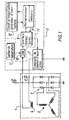
- FIG. 1 illustrates an alternator 1 comprising stator windings 3 in which an alternating voltage is generated, under the action of an inductor 4.
- a diode bridge 5 is connected to the output of the windings to deliver a rectified voltage U B + applied to the battery and to the vehicle on-board network.
- the excitation current flowing through the inductor 4 is regulated by a regulating device 2.
- a diode 6 ensures recirculation of the current in the inductor during phases where the inductor is no longer supplied by the battery.
- FIG 2A there is shown the voltage to regulate U B + as it appears at the output of the alternator or on the on-board network of the vehicle, time being plotted on the abscissa and the voltage on the ordinate.
- This voltage U B + has a ripple 20 of high frequency, which is due in particular to the diode bridge 5 ensuring the rectification of U B + .
- On this ripple is superimposed a ripple 21, of much lower frequency, which varies in amplitude as a function of variations in the excitation current in the inductor.
- the average value of the voltage U B + thus oscillates around an average voltage 22.
- the ripple 21 is of period T breaking down into two half-waves T 1 and T 2 .
- the duty cycle T 1 / (T 1 + T 2 ) can in theory vary from 0 to 100% according to the needs of the user circuits and according to the state of charge of the battery.
- This duty cycle or more exactly the duration of the alternation T 1 , is calculated using, according to the invention, two variables: a variable called excitation in closed loop EXF and a variable called excitation in open loop EXO .
- variable EXO is the one which determines the value of the alternation T 1 , ie the duration during which an excitation voltage is applied to the inductor. This variable changes rapidly from one period to another.
- the second variable EXF is used, as we will see in the following description, as an intermediary computation and it evolves much less quickly over time, which guarantees good stability of regulation.
- FIG. 2B represents slots T e which correspond to the duration during which a measurement of the voltage U B + is carried out , by sampling, during each period T.
- This measurement by sampling of duration T e is placed at the end of each period T, whatever the duty cycle, so that it ends at a time ⁇ , very short, before the end of the period T and it is equal to half a period T.
- the measurement of the voltage U B + is reliable since it lasts half a period, and the fact that it is placed at the end of the period T makes it possible to have a rapid response time from the regulation device.
- FIG. 2D shows that an interruption I 1 , caused by the timing circuit 12, triggers the appearance of an excitation slot (visible in FIG. 2C) which lasts for the entire duration T 1 loaded in the timing circuit.
- the delay circuit causes an interruption I 2 which switches the excitation to zero for the entire duration T 2 .
- Figure 3 shows the main program which is performed by the microcontroller 13 while the figure 4 shows an interrupt program, carried out at each interrupt generated by the timing circuit 12, which has a negligible duration compared to that other operations performed by the main program.
- the sampling indicator having been set on No when the program is initialized, when test 32 is performed, it is its output 33 which is chosen.
- the microcontroller therefore expects in 34 that a period of time previously loaded in memory elapses is less than T - T / 2 - ⁇ . Then the sampling indicator is set to Yes at 35.
- the wait 34 of the microcontroller can be used more profitably by performing calculations or additional treatments which are not the subject of the present invention.
- step 34 the operations of measuring the temperature ⁇ (step 37) and of calculating the reference value U ref ( ⁇ ) (step 38) can be performed in step 34.
- EXO 1 The value of EXO 1 , the calculation of which has just been described, defines the duration of the excitation slot which will be applied to the immediately following period, from time t 2 (with reference to FIG. 2).
- a test 51 is done to know the status of a control flag of interrupts D.
- step 54 the value 1 is immediately loaded into the flag D then, in 55, the value T 1 which has been calculated by the main program, that is to say the value of the variable EXO, is loaded into the timer circuit 12 so that it causes the next interruption when the time T 1 has elapsed.
- the microcontroller 13 commands the excitation current control circuit 7 to supply the inductor 4 with an excitation current, that is to say an excitation slot of duration T 1 , like those visible in FIG. 2C, then we return, in 60, to the main program.
- the timing circuit 12 causes a new interruption and the test 51 is carried out again.
- the excitation current control circuit 7 is commanded to stop supplying the inductor 4 for the entire duration T - T 1 and we return to the main program at 60.
- FIG. 5 illustrates how the reference value U ref ( ⁇ ) of the rectified voltage is calculated, from a value U ref ( ⁇ a ) predetermined for a given temperature ⁇ a .
- the function f is not necessarily a linear function but can be any.
- the reference value of the voltage output can be calculated based on other parameters of the alternator as its speed or the load which applied to him
Landscapes
- Engineering & Computer Science (AREA)
- Power Engineering (AREA)
- Control Of Eletrric Generators (AREA)
Claims (11)
- Verfahren zur Regelung des Erregungsstroms einer Erregerwicklung (4) eines Wechselstromgenerators für Kraftfahrzeuge, wobei der besagte Wechselstromgenerator insbesondere eine Gleichrichterbrücke (5) umfaßt, die eine zu regelnde gleichgerichtete Ausgangsspannung (UB +) abgibt, wobei die gleichgerichtete Spannung (UB +) eine in der Amplitude veränderliche Schwingung mit einer Niederfrequenzkomponente aufweist, die durch das Erregungssignal bedingt ist, wobei die besagte gleichgerichtete Spannung daher eine periodische Spannung ist, deren Periode T jeweils aus einer ersten Halbperiode T1, während der die Spannung der Fahrzeugbatterie an die Erregerwicklung angelegt wird, und aus einer zweiten Halbperiode T2 besteht, während der die Spannung der Batterie nicht an die Erregerwicklung angelegt wird, darin bestehend:dadurch gekennzeichnet, daß aus diesem Vergleich folgende Werte abgeleitet werden:die gleichgerichtete Spannung (UB +) durch Abtastung zu messen, das heißt durch Ausführung aufeinanderfolgender und angenäherter Messungen,den gemessenen Wert der gleichgerichteten Spannung (UB +) mit einem berechneten Bezugswert (Uref) zu vergleichen,ein erster Digitalwert (DIFF), welcher der Differenz zwischen dem gemessenen Wert der gleichgerichteten Spannung (UB +) und dem Bezugswert (Uref) entspricht,ein als Erregung in geschlossenem Regelkreis bezeichneter zweiter Digitalwert (EXF), der bei jeder Periode T dadurch berechnet wird, daß zu dem Erregungswert in geschlossenem Regelkreis der vorangehenden Periode der erste Digitalwert (DIFF) hinzugefügt wird, auf den ein erster Korrekturfaktor (A) angewendet wird,ein als Erregung in offenem Regelkreis bezeichneter dritter Digitalwert (EXO), der bei jeder Periode T dadurch berechnet wird, daß zu dem zuvor berechneten Erregungswert in geschlossenem Regelkreis bei der gleichen Periode T der erste Digitalwert (DIFF) hinzugefügt wird, auf den ein zweiter Korrekturfaktor (B) angewendet wird, wobei dieser dritte Digitalwert die Zeit T1 bestimmt, während der die Batteriespannung an die Erregerwicklung (4) angelegt wird.
- Regelungsverfahren nach Anspruch 1, dadurch gekennzeichnet, daß der zweite Korrekturfaktor (B) eine Zahl ist, deren Wert größer als der Wert des ersten Korrekturfaktors (A) ist.
- Regelungsverfahren nach einem der Ansprüche 1 oder 2, dadurch gekennzeichnet, d a ß , nachdem der zweite Digitalwert der Erregung in geschlossenem Regelkreis berechnet worden ist, ein Test stattfindet, und wenn der besagte Wert der Erregung in geschlossenem Regelkreis gleich der Dauer der Periode T ist, dann ist der dritte Digitalwert der Erregung in offenem Regelkreis gleich der Periode T.
- Regelungsverfahren nach einem der vorangehenden Ansprüche, dadurch gekennzeichnet, d a ß der Bezugswert (Uref) in Abhängigkeit von wenigstens einem Parameter berechnet wird, der mit dem Wechselstromgenerator und/oder mit der Batterie des Fahrzeugs zusammenhängt.
- Regelungsverfahren nach Anspruch 4, dadurch gekennzeichnet, daß der Bezugswert (Uref) in Abhängigkeit von der Temperatur des Wechselstromgenerators und/oder der Batterie des Fahrzeugs berechnet wird.
- Regelungsverfahren nach einem der Ansprüche 4 oder 5, dadurch gekennzeichnet, daß das Regelungsverfahren darin besteht:im Verlauf jeder Periode T eine Temperaturmessung () durchzuführen,daraus einen Bezugswert (Uref()) in Abhängigkeit von der gemessenen Temperatur () abzuleiten, wobei der besagte Bezugswert anschließend mit dem gemessenen Wert der gleichgerichteten Spannung (UB +) verglichen wird.
- Regelungsverfahren Anspruch 6, dadurch gekennzeichnet, daß der Bezugswert (Uref()) unter Zugrundelegung eines vorbestimmten Werts (Uref(a)) für eine gegebene Temperatur (a) berechnet wird, wobei auf den besagten vorbestimmten Wert (Uret(a)) ein Korrekturfaktor angewendet wird, der von der Temperatur () abhängig ist.
- Regelungsverfahren einem der Ansprüche 6 bis 7, dadurch gekennzeichnet, daß die durch Abtastung vorgenommene Messung der gleichgerichteten Spannung (UB+) mit einer Dauer Te an das Ende jeder Periode gesetzt wird, so daß sie nach einer sehr kurzen Zeit (ε) vor dem Ende der Periode T endet.
- Regelungsverfahren Anspruch 8, dadurch gekennzeichnet, daß die Dauer Te der Abtastmessung gleich einer Halbperiode ist.
- Regelungsverfahren Anspruch 8 oder 9, dadurch gekennzeichnet, daß am Ende der Dauer Te der Abtastmessung und vor dem Ende der Periode T die Berechnung des zweiten Digitalwerts (EXF) und des dritten Digitalwerts (EXO) erfolgt.
- Reglervorrichtung zur Regelung des Erregungsstroms einer Erregerwicklung (4) eines Wechselstromgenerators für Kraftfahrzeuge, wobei der besagte Wechselstromgenerator insbesondere eine Gleichrichterbrücke (5) umfaßt, die eine zu regelnde gleichgerichtete Ausgangsspannung (UB +) abgibt, wobei die gleichgerichtete Spannung (UB +) eine in der Amplitude veränderliche Schwingung mit einer Niederfrequenzkomponente aufweist, die durch das Erregungssignal bedingt ist, wobei die besagte gleichgerichtete Spannung daher eine periodische Spannung ist, deren Periode T jeweils aus einer ersten Halbperiode T1, während der die Spannung der Fahrzeugbatterie an die Erregerwicklung angelegt wird, und aus einer zweiten Halbperiode T2 besteht, während der die Spannung der Batterie nicht an die Erregerwicklung angelegt wird, bei dem das Verfahren angewendet wird, das darin besteht:dadurch gekennzeichnet, daß aus diesem Vergleich folgende Werte abgeleitet werden:die gleichgerichtete Spannung (UB +) durch Abtastung zu messen, das heißt durch Ausführung aufeinanderfolgender und angenäherter Messungen,den gemessenen Wert der gleichgerichteten Spannung (UB +) mit einem berechneten Bezugswert (UREF) zu vergleichen,ein erster Digitalwert (DIFF), welcher der Differenz zwischen dem gemessenen Wert der gleichgerichteten Spannung (UB +) und dem Bezugswert (UREF) entspricht,ein als Erregung in geschlossenem Regelkreis bezeichneter zweiter Digitalwert (EXF), der bei jeder Periode T dadurch berechnet wird, daß zu dem Erregungswert in geschlossenem Regelkreis der vorangehenden Periode der erste Digitalwert (DIFF) hinzugefügt wird, auf den ein erster Korrekturfaktor (A) angewendet wird,ein als Erregung in offenem Regelkreis bezeichneter dritter Digitalwert (EXO), der bei jeder Periode T dadurch berechnet wird, daß zu dem zuvor berechneten Erregungswert in geschlossenem Regelkreis bei der gleichen Periode T der erste Digitalwert (DIFF) hinzugefügt wird, auf den ein zweiter Korrekturfaktor (B) angewendet wird, wobei dieser dritte Digitalwert die Zeit T1 bestimmt, während der die Batteriespannung an die Erregerwicklung (4) angelegt wird.
Applications Claiming Priority (2)
| Application Number | Priority Date | Filing Date | Title |
|---|---|---|---|
| FR9604856 | 1996-04-18 | ||
| FR9604856A FR2747860B1 (fr) | 1996-04-18 | 1996-04-18 | Procede de regulation par traitement numerique du courant d'excitation d'un alternateur de vehicule automobile et dispositif regulateur mettant en oeuvre un tel procede |
Publications (2)
| Publication Number | Publication Date |
|---|---|
| EP0802464A1 EP0802464A1 (de) | 1997-10-22 |
| EP0802464B1 true EP0802464B1 (de) | 2003-08-06 |
Family
ID=9491331
Family Applications (1)
| Application Number | Title | Priority Date | Filing Date |
|---|---|---|---|
| EP97105833A Expired - Lifetime EP0802464B1 (de) | 1996-04-18 | 1997-04-09 | Verfahren zur Steuerung des Erregungstroms eines Fahrzeuggenerators mit digitaler Verarbeitung und Steuerungsvorrichtung zur Durchführung dieses Verfahrens |
Country Status (6)
| Country | Link |
|---|---|
| US (1) | US6081103A (de) |
| EP (1) | EP0802464B1 (de) |
| CN (1) | CN1075683C (de) |
| DE (1) | DE69723902T2 (de) |
| ES (1) | ES2205082T3 (de) |
| FR (1) | FR2747860B1 (de) |
Families Citing this family (16)
| Publication number | Priority date | Publication date | Assignee | Title |
|---|---|---|---|---|
| DE19827556A1 (de) * | 1998-06-20 | 1999-12-23 | Bosch Gmbh Robert | Spannungsregler für einen von einer Brennkraftmaschine antreibbaren Generator |
| FR2799905B1 (fr) * | 1999-10-18 | 2001-12-21 | Renault | Procede de regulation d'une puissance mecanique prelevee par un alternateur |
| TW546888B (en) | 2000-06-26 | 2003-08-11 | Snap On Tools Co | Alternator testing method and system using ripple detection |
| FR2821699B1 (fr) * | 2001-03-02 | 2003-05-30 | Valeo Equip Electr Moteur | Alternateur de vehicule automobile a sortie d'information d'excitation |
| FR2830380B1 (fr) * | 2001-09-28 | 2005-01-07 | Valeo Equip Electr Moteur | Dispositif de limitation de la temperature de l'enroulement inducteur du rotor d'une machine electrique tournante et dispositif de charge d'une batterie pourvu d'un tel dispositif de controle |
| US6862504B2 (en) | 2002-09-10 | 2005-03-01 | Bendix Commercial Vehicle Systems Llc | System and method for detecting alternator condition |
| JP2006280193A (ja) * | 2005-03-03 | 2006-10-12 | Toyota Motor Corp | 駆動回路の異常判定装置およびこれを備える駆動装置並びに駆動回路の異常判定方法 |
| FR2886411B1 (fr) * | 2005-05-31 | 2008-01-11 | Valeo Equip Electr Moteur | Procede et dispositif d'estimation du courant delivre par un alternateur pour vehicule automobile |
| JP4161081B2 (ja) * | 2006-04-12 | 2008-10-08 | 三菱電機株式会社 | 制御装置一体型発電電動機 |
| WO2009093101A1 (en) * | 2008-01-21 | 2009-07-30 | Freescale Semiconductor, Inc. | Method and apparatus for regulating a field current for an alternator device |
| DE102010029507A1 (de) * | 2010-05-31 | 2011-12-01 | Robert Bosch Gmbh | Verfahren und Vorrichtung zur Erzeugung von diskreten Werten eines Stromes mittels einer Induktivität zur Begrenzung eines Erregerstromes für einen Kraftfahrzeuggenerator |
| US9590548B2 (en) * | 2014-09-25 | 2017-03-07 | Nxp Usa, Inc. | Method and apparatus for regulating an output voltage of an alternator |
| DE102015223900A1 (de) * | 2015-11-18 | 2017-05-18 | Robert Bosch Gmbh | Verfahren und Vorrichtung zum Erkennen einer Drehzahl in einer Generatoreinheit |
| US10199968B2 (en) * | 2017-05-22 | 2019-02-05 | Infineon Technologies Ag | Fault handling for alternator control devices |
| US10250173B1 (en) * | 2017-09-19 | 2019-04-02 | Kutai Electronics Industry Co., Ltd. | Power generator system and generator exciter device thereof |
| EP3703244B1 (de) * | 2019-02-26 | 2023-09-13 | Mahle International GmbH | Verfahren zum betrieb eines elektrischen generators |
Family Cites Families (10)
| Publication number | Priority date | Publication date | Assignee | Title |
|---|---|---|---|---|
| EP0158636B1 (de) * | 1982-12-06 | 1990-04-11 | Tommy WAHLSTRÖM | Verfahren zum laden einer aufladbaren batterie |
| JPS60121932A (ja) * | 1983-12-05 | 1985-06-29 | 株式会社デンソー | 車両充電発電機用制御装置 |
| EP0330561B1 (de) * | 1988-02-23 | 1993-03-24 | Valeo Equipements Electriques Moteur | Mehrfunktionsregeleinrichtung mit Taktsynchronwechselstromerzeuger |
| US5157321A (en) * | 1988-04-26 | 1992-10-20 | Nippondenso Co., Ltd. | Charging control apparatus for vehicle |
| JPH01287703A (ja) * | 1988-05-14 | 1989-11-20 | Nkk Corp | 追値制御系の制御方法 |
| US5130920A (en) * | 1989-09-15 | 1992-07-14 | Eastman Kodak Company | Adaptive process control system, especially for control of temperature of flowing fluids |
| FR2667998B1 (fr) * | 1990-10-15 | 1992-12-04 | Valeo Equip Electr Moteur | Procede et dispositif de regulation d'un alternateur. |
| DE4141837B4 (de) * | 1991-12-18 | 2006-08-03 | Robert Bosch Gmbh | Vorrichtung zur Regelung eines Generators |
| US5444354A (en) * | 1992-03-02 | 1995-08-22 | Hitachi, Ltd. | Charging generator control for vehicles |
| FR2701609B1 (fr) * | 1993-02-12 | 1995-05-12 | Valeo Equip Electr Moteur | Circuit régulateur à excitation progressive pour la charge d'une batterie par un alternateur. |
-
1996
- 1996-04-18 FR FR9604856A patent/FR2747860B1/fr not_active Expired - Fee Related
-
1997
- 1997-04-09 EP EP97105833A patent/EP0802464B1/de not_active Expired - Lifetime
- 1997-04-09 ES ES97105833T patent/ES2205082T3/es not_active Expired - Lifetime
- 1997-04-09 DE DE69723902T patent/DE69723902T2/de not_active Expired - Lifetime
- 1997-04-15 US US08/837,969 patent/US6081103A/en not_active Expired - Lifetime
- 1997-04-17 CN CN97110546A patent/CN1075683C/zh not_active Expired - Lifetime
Also Published As
| Publication number | Publication date |
|---|---|
| CN1075683C (zh) | 2001-11-28 |
| US6081103A (en) | 2000-06-27 |
| DE69723902D1 (de) | 2003-09-11 |
| ES2205082T3 (es) | 2004-05-01 |
| CN1169058A (zh) | 1997-12-31 |
| FR2747860B1 (fr) | 1998-05-22 |
| EP0802464A1 (de) | 1997-10-22 |
| DE69723902T2 (de) | 2004-07-22 |
| FR2747860A1 (fr) | 1997-10-24 |
Similar Documents
| Publication | Publication Date | Title |
|---|---|---|
| EP0802606B1 (de) | Verfahren zur Steuerung des Erregungstroms eines Fahrzeuggenerators mit digitaler Verarbeitung und Steuerungsvorrichtung zur Durchführung dieses Verfahrens | |
| EP0802464B1 (de) | Verfahren zur Steuerung des Erregungstroms eines Fahrzeuggenerators mit digitaler Verarbeitung und Steuerungsvorrichtung zur Durchführung dieses Verfahrens | |
| FR2865038A1 (fr) | Dispositif de mesure d'un vecteur synchrome | |
| FR2901647A1 (fr) | Dispositif et procede de commande de puissance pour une machine dynamo electrique du type a enroulement de champ | |
| FR2897945A1 (fr) | Dispositif destine a calculer une quantite indiquant l'etat charge d'une batterie installee sur un vehicule | |
| FR2829088A1 (fr) | Dispositif de commande de braquage | |
| EP1283425A1 (de) | Verfahren zur Abschätzung von Hochleistungsbatterie-parametern eines Elektromotorfahrzeugs | |
| EP2954335B1 (de) | Verfahren zur bestimmung des durchschnittswertes eines periodischen oder quasiperiodischen spannungssignals | |
| EP0481862B1 (de) | Verfahren und Vorrichtung zur Regelung eines Wechselstromgenerators | |
| FR2627593A1 (fr) | Appareil pour faire le diagnostic d'une batterie montee sur un vehicule | |
| EP0738036A1 (de) | Geschwindigkeitsregelungsverfahren für einen elektrischen Motor | |
| EP2158672B1 (de) | Elektrische drehmaschine und verfahren zu ihrer steuerung | |
| FR2662628A1 (fr) | Dispositif de commande d'une machine de coupe. | |
| WO1997048164A1 (fr) | Procede et dispositif de commande d'un alternateur de vehicule automobile | |
| EP0616411A1 (de) | Schnelladeverfahren für Batterie und integrierter Schaltkreis zur Durchführung des Verfahrens | |
| FR2766991A1 (fr) | Procede pour la regulation par traitement numerique du courant d'excitation d'un alternateur de vehicule automobile et dispositif regulateur mettant en oeuvre un tel procede | |
| EP1462815B1 (de) | Verfahren und Vorrichtung zur Bestimmung des Ladeszustands einer Batterie und Verwendung eines solchen Verfahrens in einem Ladungsmanager | |
| FR3087162A1 (fr) | Systeme de diagnostic sur place de la batterie d'un velo electrique | |
| EP0596789A1 (de) | Verfahren und Vorrichtung zum Messen der Ladung einer Akkumulatorenbatterie | |
| EP0328838A1 (de) | Regelvorrichtung für einen Gleichstrommotor, insbesondere zur Regelung der Öffnungen an einem Fahrzeug | |
| EP1336857B1 (de) | Anordnung zur Bestimmung des Ladezustands einer Batterie, insbesondere zur Verwendung in einem Kraftfahrzeug | |
| EP1943725B1 (de) | Messung eines von einer elektrischen drehmaschine wie ein generator gelieferten stroms | |
| FR2797530A1 (fr) | Procede et systeme pour la commande de coupure de demarreur de vehicule automobile | |
| FR2864723A1 (fr) | Dispositif de commande pour un generateur electrique de vehicule a moteur | |
| FR2747861A1 (fr) | Procede et dispositif de regulation de la tension de sortie d'un alternateur par traitement numerique dans lequel la tension de sortie de l'alternateur est mesuree par echantillonnage |
Legal Events
| Date | Code | Title | Description |
|---|---|---|---|
| PUAI | Public reference made under article 153(3) epc to a published international application that has entered the european phase |
Free format text: ORIGINAL CODE: 0009012 |
|
| AK | Designated contracting states |
Kind code of ref document: A1 Designated state(s): DE ES GB IT |
|
| 17P | Request for examination filed |
Effective date: 19980324 |
|
| 17Q | First examination report despatched |
Effective date: 20001004 |
|
| GRAH | Despatch of communication of intention to grant a patent |
Free format text: ORIGINAL CODE: EPIDOS IGRA |
|
| GRAH | Despatch of communication of intention to grant a patent |
Free format text: ORIGINAL CODE: EPIDOS IGRA |
|
| GRAA | (expected) grant |
Free format text: ORIGINAL CODE: 0009210 |
|
| AK | Designated contracting states |
Designated state(s): DE ES GB IT |
|
| REG | Reference to a national code |
Ref country code: GB Ref legal event code: FG4D Free format text: NOT ENGLISH |
|
| REF | Corresponds to: |
Ref document number: 69723902 Country of ref document: DE Date of ref document: 20030911 Kind code of ref document: P |
|
| GBT | Gb: translation of ep patent filed (gb section 77(6)(a)/1977) |
Effective date: 20031029 |
|
| PG25 | Lapsed in a contracting state [announced via postgrant information from national office to epo] |
Ref country code: ES Free format text: LAPSE BECAUSE OF NON-PAYMENT OF DUE FEES Effective date: 20040410 |
|
| REG | Reference to a national code |
Ref country code: ES Ref legal event code: FG2A Ref document number: 2205082 Country of ref document: ES Kind code of ref document: T3 |
|
| PLBE | No opposition filed within time limit |
Free format text: ORIGINAL CODE: 0009261 |
|
| STAA | Information on the status of an ep patent application or granted ep patent |
Free format text: STATUS: NO OPPOSITION FILED WITHIN TIME LIMIT |
|
| 26N | No opposition filed |
Effective date: 20040507 |
|
| REG | Reference to a national code |
Ref country code: ES Ref legal event code: FD2A Effective date: 20040410 |
|
| PGFP | Annual fee paid to national office [announced via postgrant information from national office to epo] |
Ref country code: GB Payment date: 20130415 Year of fee payment: 17 |
|
| PGFP | Annual fee paid to national office [announced via postgrant information from national office to epo] |
Ref country code: IT Payment date: 20130422 Year of fee payment: 18 |
|
| GBPC | Gb: european patent ceased through non-payment of renewal fee |
Effective date: 20140409 |
|
| PG25 | Lapsed in a contracting state [announced via postgrant information from national office to epo] |
Ref country code: GB Free format text: LAPSE BECAUSE OF NON-PAYMENT OF DUE FEES Effective date: 20140409 |
|
| PG25 | Lapsed in a contracting state [announced via postgrant information from national office to epo] |
Ref country code: IT Free format text: LAPSE BECAUSE OF NON-PAYMENT OF DUE FEES Effective date: 20150409 |
|
| PGFP | Annual fee paid to national office [announced via postgrant information from national office to epo] |
Ref country code: DE Payment date: 20160413 Year of fee payment: 20 |
|
| REG | Reference to a national code |
Ref country code: DE Ref legal event code: R071 Ref document number: 69723902 Country of ref document: DE |