EP0802364A2 - Cache pour recouvrir des ouvertures murales - Google Patents
Cache pour recouvrir des ouvertures murales Download PDFInfo
- Publication number
- EP0802364A2 EP0802364A2 EP97105825A EP97105825A EP0802364A2 EP 0802364 A2 EP0802364 A2 EP 0802364A2 EP 97105825 A EP97105825 A EP 97105825A EP 97105825 A EP97105825 A EP 97105825A EP 0802364 A2 EP0802364 A2 EP 0802364A2
- Authority
- EP
- European Patent Office
- Prior art keywords
- wall
- locking
- retaining
- panel according
- feature
- Prior art date
- Legal status (The legal status is an assumption and is not a legal conclusion. Google has not performed a legal analysis and makes no representation as to the accuracy of the status listed.)
- Granted
Links
Images


Classifications
-
- H—ELECTRICITY
- H02—GENERATION; CONVERSION OR DISTRIBUTION OF ELECTRIC POWER
- H02G—INSTALLATION OF ELECTRIC CABLES OR LINES, OR OF COMBINED OPTICAL AND ELECTRIC CABLES OR LINES
- H02G3/00—Installations of electric cables or lines or protective tubing therefor in or on buildings, equivalent structures or vehicles
- H02G3/22—Installations of cables or lines through walls, floors or ceilings, e.g. into buildings
-
- F—MECHANICAL ENGINEERING; LIGHTING; HEATING; WEAPONS; BLASTING
- F16—ENGINEERING ELEMENTS AND UNITS; GENERAL MEASURES FOR PRODUCING AND MAINTAINING EFFECTIVE FUNCTIONING OF MACHINES OR INSTALLATIONS; THERMAL INSULATION IN GENERAL
- F16L—PIPES; JOINTS OR FITTINGS FOR PIPES; SUPPORTS FOR PIPES, CABLES OR PROTECTIVE TUBING; MEANS FOR THERMAL INSULATION IN GENERAL
- F16L5/00—Devices for use where pipes, cables or protective tubing pass through walls or partitions
Definitions
- the invention relates to panels for installation ducts such as cable routing ducts, device installation ducts, cable trays, etc. for covering wall openings, in accordance with the preamble of claim 1.
- a so-called corner bracket kit is commercially available, consisting of two corner pieces with locking bars, a wall sheet profile guide piece and aluminum wall sheet profile rails. The latter are cut to length from a standard rail according to the channel height and depth and clipped onto the corner bracket kit.
- corner bracket kit is commercially available, consisting of two corner pieces with locking bars, a wall sheet profile guide piece and aluminum wall sheet profile rails. The latter are cut to length from a standard rail according to the channel height and depth and clipped onto the corner bracket kit.
- the present invention has for its object to provide an aperture of the type mentioned, which is simple and inexpensive, which sits firmly, but can also be quickly assembled and disassembled, which can be adapted to any channel size and which in particular produces an optically satisfactory image .
- the panel according to the invention uses four prefabricated lamination corners, in particular molded from plastic, and four matching profile rails, which are cut to length by a prefabricated profile bar.
- the connection takes place by means of a snap-in connection, the snap-in means being arranged in such a way that the cut edges of the profile rails are covered by the lamination corners, so that any inaccuracies remain invisible. Thanks to the snap-in connection, length compensation is also possible within certain limits, so that a cover that exactly matches the respective installation duct can be produced in any case.
- the wall bracket is fixed to the perforated wall and / or the duct. It has special retaining lugs with a toothed active surface, which interact with retaining springs provided on the back of the lamination corners, which also have a toothed active surface.
- the locking slide which has a corresponding bracket, ensures that the retaining springs on the lamination corners are freely movable during assembly and can be removed from the retaining lugs of the wall bracket; in the end or locking position, however, the retaining springs are blocked so that the panel can no longer be removed.
- a retaining strip is formed on the back of the profile rail, specifically on the longitudinal edge adjacent to the channel, which is oriented parallel to the surface of the channel. Formed into a retaining edge in this retaining strip, which corresponds to a locking lug on the locking tongue of the locking slide and fixes the locking slide in the locked position.
- the side edges of the lamination corners preferably form an obtuse angle to one another. This ensures a wide coverage of the cut edges of the profile rails.
- the visible surfaces of the screen form an acute angle to the wall surface. This gives the cover a visually pleasing impression and reduces the installation on the wall.
- the wall brackets are preferably equipped with an adhesive layer on their surface facing the duct, which facilitates the assembly of the wall brackets and improves the correct fit of the panel.
- Fig. 1 shows a perspective view of a cable duct 1 with cover 2, which breaks through a wall 3.
- the wall opening is covered with a panel 10.
- This consists of four laminating corners 20.1 ... 20.4 and four profile rails 40.1 ... 40.4.
- Kaschierecken 20 and profile bars 40 are plugged together.
- a locking slide 50 makes it possible to fix the panel 10 after positioning in front of the wall opening.
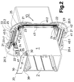
- FIG. 2 shows a view of the rear of channel 1, 2 and panel 10.
- a wall holder 30 is mounted on a narrow side of the channel 1 with the aid of an adhesive layer 39. Whose surface facing the wall surface is equipped with two holes 31 for a possible screw assembly. Parallel to channel 1, a tongue 32 can be seen which interacts with the profile rails 40. In addition, one can see on the wall bracket 30 two retaining lugs 33, 34 with a toothed active surface 35 which interacts with the liner corners 20.
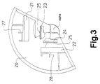
- the construction of the liner corners 20 results from the top view of the back of a liner corner 20 in an enlarged view according to FIG. 3.
- Two latching tongues 21, 22 oriented at right angles to one another can be seen, which cooperate with the teeth 41, 42.
- the side edges of the liner corners 20 mutually form an obtuse angle alpha.
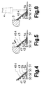
- the locking slide 50 is provided. This is pushed onto the holding bar 43 of a profile rail 40.4, for which purpose it is equipped with a corresponding holder 53. This is shown in FIGS. 4, 5 and 6.
- the locking slide 50 also has a central recess 54 in which a resilient locking tongue 52 is seated, which is equipped with a locking lug 55. Finally, a visible part 51 is also provided, which defines the end or locked state of the locking slide 50.
- Fig. 4 shows excerpts of the relative position of locking slide 50 and rail 40.4 in the delivery state.
- the locking slide 50 is pulled out so far that the locking lug 55 is visible.
- FIG. 5 shows the combination of FIG. 4 in the final or locked state in front of a wall 3.
- the locking slide 50 is pushed so far below the profile rail 40.4 that the locking lug 55 engages behind a locking edge 45 provided on the retaining strip 43.
- FIG. 6 shows the situation when dismantling the panel 10. With the tip of a screwdriver 4, the locking tab 55 is released from the locking edge 45 by bending the locking tongue 52 and the locking slide 50 is pulled forward.
- Fig. 7 shows in part the combination of profile rail 40.4, locking slide 50 and wall bracket 30 in front of the perforated wall 3.
- a bracket 53 is formed on the rear of the locking slide 50, which corresponds to the retaining spring 23 on the back of the concealment corner 20.
- the holder 53 and the holding spring 23 are separated.
- the retaining spring 23 is resiliently movable, the liner corner 20 and thus the entire panel 10 can be removed from the retaining lugs 33, 34 of the wall bracket 30.
- Fig. 8 shows the situation in the final or locked state.
- the bracket 53 now blocks the retaining spring 23.
- the latching connection between the retaining spring 23 and the latch 33 can no longer be released, the panel 10 is permanently fixed.
- Fig. 9 shows the situation during disassembly.
- the locking slide 50 is moved into the released position.
- the holder 53 has released the retaining spring 23, so that the panel 10 can be removed from the toothed active surfaces 35 of the retaining lugs 33, 34 of the wall holder 30.
- the tongues 32 on the wall bracket 30 are arranged so that they clamp the retaining bar 43, as is necessary for a firm but releasable hold of the panel 10.
Landscapes
- Engineering & Computer Science (AREA)
- Architecture (AREA)
- Civil Engineering (AREA)
- Structural Engineering (AREA)
- General Engineering & Computer Science (AREA)
- Mechanical Engineering (AREA)
- Air Bags (AREA)
- Fire-Detection Mechanisms (AREA)
- Professional, Industrial, Or Sporting Protective Garments (AREA)
- Finishing Walls (AREA)
- Emergency Lowering Means (AREA)
- Turbine Rotor Nozzle Sealing (AREA)
- Farming Of Fish And Shellfish (AREA)
- Drilling And Exploitation, And Mining Machines And Methods (AREA)
- Building Environments (AREA)
- Details Of Indoor Wiring (AREA)
Applications Claiming Priority (2)
| Application Number | Priority Date | Filing Date | Title |
|---|---|---|---|
| DE29606987U DE29606987U1 (de) | 1996-04-19 | 1996-04-19 | Blende zum Kaschieren von Wanddurchbrüchen |
| DE29606987U | 1996-04-19 |
Publications (3)
| Publication Number | Publication Date |
|---|---|
| EP0802364A2 true EP0802364A2 (fr) | 1997-10-22 |
| EP0802364A3 EP0802364A3 (fr) | 1998-04-08 |
| EP0802364B1 EP0802364B1 (fr) | 1999-08-04 |
Family
ID=8022718
Family Applications (1)
| Application Number | Title | Priority Date | Filing Date |
|---|---|---|---|
| EP97105825A Expired - Lifetime EP0802364B1 (fr) | 1996-04-19 | 1997-04-09 | Cache pour recouvrir des ouvertures murales |
Country Status (5)
| Country | Link |
|---|---|
| EP (1) | EP0802364B1 (fr) |
| AT (1) | ATE182969T1 (fr) |
| DE (2) | DE29606987U1 (fr) |
| DK (1) | DK0802364T3 (fr) |
| ES (1) | ES2137032T3 (fr) |
Cited By (1)
| Publication number | Priority date | Publication date | Assignee | Title |
|---|---|---|---|---|
| FR2805095A1 (fr) * | 2000-02-14 | 2001-08-17 | Planet Wattohm Sa | Adaptateur pour le raccordement de deux conduits de cablage intervenant de part et d'autre d'un faux-plafond |
Families Citing this family (1)
| Publication number | Priority date | Publication date | Assignee | Title |
|---|---|---|---|---|
| DE29922514U1 (de) * | 1999-12-22 | 2001-05-31 | Tehalit GmbH & Co. KG, 67716 Heltersberg | Blende zum Kaschieren von Wanddurchbrüchen |
Family Cites Families (2)
| Publication number | Priority date | Publication date | Assignee | Title |
|---|---|---|---|---|
| DE2809463C2 (de) * | 1978-03-04 | 1982-09-30 | Neuwalzwerk Bettermann Ohg, 5750 Menden | Brandabweisende Kabeldurchführung durch Trennwände o.dgl. |
| DE9003636U1 (de) * | 1990-03-28 | 1990-05-31 | CSD International B.V., Opmeer | Anordnung zur Vermeidung der Fortpflanzung von beispielsweise Feuer, Wasser oder (Rauch-) Gas über Kabel |
-
1996
- 1996-04-19 DE DE29606987U patent/DE29606987U1/de not_active Expired - Lifetime
-
1997
- 1997-04-09 DE DE59700299T patent/DE59700299D1/de not_active Expired - Fee Related
- 1997-04-09 ES ES97105825T patent/ES2137032T3/es not_active Expired - Lifetime
- 1997-04-09 AT AT97105825T patent/ATE182969T1/de not_active IP Right Cessation
- 1997-04-09 DK DK97105825T patent/DK0802364T3/da active
- 1997-04-09 EP EP97105825A patent/EP0802364B1/fr not_active Expired - Lifetime
Cited By (3)
| Publication number | Priority date | Publication date | Assignee | Title |
|---|---|---|---|---|
| FR2805095A1 (fr) * | 2000-02-14 | 2001-08-17 | Planet Wattohm Sa | Adaptateur pour le raccordement de deux conduits de cablage intervenant de part et d'autre d'un faux-plafond |
| EP1126570A1 (fr) * | 2000-02-14 | 2001-08-22 | Planet Wattohm | Adaptateur pour le raccordement de deux conduits de câblage intervenant de part et d'autre d'un fauxplafond |
| US6479750B1 (en) | 2000-02-14 | 2002-11-12 | Planet Wattohm | Adapter for interconnecting two wiring ducts on opposite sides of a suspended ceiling |
Also Published As
| Publication number | Publication date |
|---|---|
| DE29606987U1 (de) | 1997-08-14 |
| ES2137032T3 (es) | 1999-12-01 |
| DK0802364T3 (da) | 2000-03-06 |
| EP0802364B1 (fr) | 1999-08-04 |
| ATE182969T1 (de) | 1999-08-15 |
| DE59700299D1 (de) | 1999-09-09 |
| EP0802364A3 (fr) | 1998-04-08 |
Similar Documents
| Publication | Publication Date | Title |
|---|---|---|
| EP2814356B1 (fr) | Tiroir | |
| DE29623551U1 (de) | Schaltschrank | |
| DE10107864A1 (de) | Halteelement für Abdeckleisten | |
| EP1803339A1 (fr) | Boitier ou unite de reception de type baie, a baguette de marquage | |
| EP1072179B1 (fr) | Support de modules | |
| EP0802364B1 (fr) | Cache pour recouvrir des ouvertures murales | |
| EP1260002A1 (fr) | Coffret pour le logement de composants electriques et/ou electroniques | |
| DE4200124A1 (de) | Befestigungsvorrichtung fuer eine gebaeudewandverkleidung | |
| DE3241016C2 (de) | Baugruppenträger für elektronische Baugruppen, insbesondere Leiterplatten | |
| DE29909946U1 (de) | Leitungsführungskanal für den frontseitigen Einbau von Elektroinstallationsgeräten | |
| EP0903063B1 (fr) | Boitier | |
| DE8707366U1 (de) | Büro-Arbeitstisch | |
| WO2005033526A1 (fr) | Element de recouvrement pouvant etre fixe a un profile fonctionnel ou a une garniture au moyen d'une attache de type clip | |
| DE69113590T2 (de) | Leuchte mit zugehörigem Gitter. | |
| DE19821898C1 (de) | Regalsystem | |
| DE102013103594B4 (de) | Halteteil für eine Montageplatte, Türbetätiger-Anordnung und Verfahren zum Montieren einer Türbetätiger-Anordnung | |
| DE10061033B4 (de) | Blende zum Kaschieren von Wanddurchbrüchen | |
| DE4137687C2 (fr) | ||
| EP2133503A2 (fr) | Panneau de porte et porte | |
| EP1635006B1 (fr) | Elément de plafond | |
| DE10218128C1 (de) | Bauteil zur Befestigung in einer Gehäuseöffnung | |
| DE19519416C1 (de) | Anschlußübergangseinrichtung | |
| DE29600186U1 (de) | Kastenmöbel, insbesondere Küchenmöbelschrank mit integrierter Rückwandleuchte | |
| EP3244001A1 (fr) | Porte comprenant une piece de serrage commandee par ressort et son procede de montage | |
| DE2909521C2 (de) | Hängeschrank mit einer an seinem Unterboden befestigten Lichtblende |
Legal Events
| Date | Code | Title | Description |
|---|---|---|---|
| PUAI | Public reference made under article 153(3) epc to a published international application that has entered the european phase |
Free format text: ORIGINAL CODE: 0009012 |
|
| AK | Designated contracting states |
Kind code of ref document: A2 Designated state(s): AT BE CH DE DK ES FI FR GB IT LI NL SE |
|
| PUAL | Search report despatched |
Free format text: ORIGINAL CODE: 0009013 |
|
| AK | Designated contracting states |
Kind code of ref document: A3 Designated state(s): AT BE CH DE DK ES FI FR GB IT LI NL SE |
|
| 17P | Request for examination filed |
Effective date: 19980428 |
|
| GRAG | Despatch of communication of intention to grant |
Free format text: ORIGINAL CODE: EPIDOS AGRA |
|
| 17Q | First examination report despatched |
Effective date: 19981222 |
|
| GRAG | Despatch of communication of intention to grant |
Free format text: ORIGINAL CODE: EPIDOS AGRA |
|
| GRAH | Despatch of communication of intention to grant a patent |
Free format text: ORIGINAL CODE: EPIDOS IGRA |
|
| GRAH | Despatch of communication of intention to grant a patent |
Free format text: ORIGINAL CODE: EPIDOS IGRA |
|
| GRAA | (expected) grant |
Free format text: ORIGINAL CODE: 0009210 |
|
| AK | Designated contracting states |
Kind code of ref document: B1 Designated state(s): AT BE CH DE DK ES FI FR GB IT LI NL SE |
|
| REF | Corresponds to: |
Ref document number: 182969 Country of ref document: AT Date of ref document: 19990815 Kind code of ref document: T |
|
| REG | Reference to a national code |
Ref country code: CH Ref legal event code: EP |
|
| REF | Corresponds to: |
Ref document number: 59700299 Country of ref document: DE Date of ref document: 19990909 |
|
| ITF | It: translation for a ep patent filed | ||
| REG | Reference to a national code |
Ref country code: CH Ref legal event code: NV Representative=s name: PATENTANWAELTE SCHAAD, BALASS, MENZL & PARTNER AG |
|
| GBT | Gb: translation of ep patent filed (gb section 77(6)(a)/1977) |
Effective date: 19991019 |
|
| ET | Fr: translation filed | ||
| REG | Reference to a national code |
Ref country code: ES Ref legal event code: FG2A Ref document number: 2137032 Country of ref document: ES Kind code of ref document: T3 |
|
| REG | Reference to a national code |
Ref country code: DK Ref legal event code: T3 |
|
| PLBE | No opposition filed within time limit |
Free format text: ORIGINAL CODE: 0009261 |
|
| STAA | Information on the status of an ep patent application or granted ep patent |
Free format text: STATUS: NO OPPOSITION FILED WITHIN TIME LIMIT |
|
| 26N | No opposition filed | ||
| REG | Reference to a national code |
Ref country code: GB Ref legal event code: IF02 |
|
| PGFP | Annual fee paid to national office [announced via postgrant information from national office to epo] |
Ref country code: GB Payment date: 20030317 Year of fee payment: 7 |
|
| PGFP | Annual fee paid to national office [announced via postgrant information from national office to epo] |
Ref country code: DE Payment date: 20030328 Year of fee payment: 7 |
|
| PGFP | Annual fee paid to national office [announced via postgrant information from national office to epo] |
Ref country code: NL Payment date: 20030416 Year of fee payment: 7 |
|
| PGFP | Annual fee paid to national office [announced via postgrant information from national office to epo] |
Ref country code: FR Payment date: 20030417 Year of fee payment: 7 |
|
| PGFP | Annual fee paid to national office [announced via postgrant information from national office to epo] |
Ref country code: ES Payment date: 20030422 Year of fee payment: 7 |
|
| PGFP | Annual fee paid to national office [announced via postgrant information from national office to epo] |
Ref country code: AT Payment date: 20030424 Year of fee payment: 7 |
|
| PGFP | Annual fee paid to national office [announced via postgrant information from national office to epo] |
Ref country code: SE Payment date: 20030425 Year of fee payment: 7 Ref country code: FI Payment date: 20030425 Year of fee payment: 7 Ref country code: DK Payment date: 20030425 Year of fee payment: 7 Ref country code: CH Payment date: 20030425 Year of fee payment: 7 Ref country code: BE Payment date: 20030425 Year of fee payment: 7 |
|
| PG25 | Lapsed in a contracting state [announced via postgrant information from national office to epo] |
Ref country code: GB Free format text: LAPSE BECAUSE OF NON-PAYMENT OF DUE FEES Effective date: 20040409 Ref country code: FI Free format text: LAPSE BECAUSE OF NON-PAYMENT OF DUE FEES Effective date: 20040409 Ref country code: AT Free format text: LAPSE BECAUSE OF NON-PAYMENT OF DUE FEES Effective date: 20040409 |
|
| PG25 | Lapsed in a contracting state [announced via postgrant information from national office to epo] |
Ref country code: SE Free format text: LAPSE BECAUSE OF NON-PAYMENT OF DUE FEES Effective date: 20040410 Ref country code: ES Free format text: LAPSE BECAUSE OF NON-PAYMENT OF DUE FEES Effective date: 20040410 |
|
| PG25 | Lapsed in a contracting state [announced via postgrant information from national office to epo] |
Ref country code: LI Free format text: LAPSE BECAUSE OF NON-PAYMENT OF DUE FEES Effective date: 20040430 Ref country code: DK Free format text: LAPSE BECAUSE OF NON-PAYMENT OF DUE FEES Effective date: 20040430 Ref country code: CH Free format text: LAPSE BECAUSE OF NON-PAYMENT OF DUE FEES Effective date: 20040430 Ref country code: BE Free format text: LAPSE BECAUSE OF NON-PAYMENT OF DUE FEES Effective date: 20040430 |
|
| BERE | Be: lapsed |
Owner name: *TEHALIT G.M.B.H. Effective date: 20040430 |
|
| PG25 | Lapsed in a contracting state [announced via postgrant information from national office to epo] |
Ref country code: NL Free format text: LAPSE BECAUSE OF NON-PAYMENT OF DUE FEES Effective date: 20041101 |
|
| PG25 | Lapsed in a contracting state [announced via postgrant information from national office to epo] |
Ref country code: DE Free format text: LAPSE BECAUSE OF NON-PAYMENT OF DUE FEES Effective date: 20041103 |
|
| EUG | Se: european patent has lapsed | ||
| GBPC | Gb: european patent ceased through non-payment of renewal fee |
Effective date: 20040409 |
|
| REG | Reference to a national code |
Ref country code: CH Ref legal event code: PL |
|
| PG25 | Lapsed in a contracting state [announced via postgrant information from national office to epo] |
Ref country code: FR Free format text: LAPSE BECAUSE OF NON-PAYMENT OF DUE FEES Effective date: 20041231 |
|
| NLV4 | Nl: lapsed or anulled due to non-payment of the annual fee |
Effective date: 20041101 |
|
| REG | Reference to a national code |
Ref country code: FR Ref legal event code: ST |
|
| PG25 | Lapsed in a contracting state [announced via postgrant information from national office to epo] |
Ref country code: IT Free format text: LAPSE BECAUSE OF NON-PAYMENT OF DUE FEES Effective date: 20050409 |
|
| REG | Reference to a national code |
Ref country code: ES Ref legal event code: FD2A Effective date: 20040410 |